
Related Manuals for Cincoze P2102 Series


Summary of Contents for Cincoze P2102 Series
- Page 1 P2102 Series User Manual High Performance Convertible Computer 8th Generation Intel® Core™ U Series Embedded Computer with CDS Technology Version: V1.09...
-
Page 2: Table Of Contents
1.7 Mechanical Dimension …………………………………….………...………..……..18 Chapter 2 Switches and Connectors 2.1 Location of Switches and Connectors ………….………………………………...………..20 2.1.1 Top View ……………………………….……………………………………...………..20 2.1.2 Bottom View ……………………………………………………………...……....20 2.2 Switches and Connectors Definition…………………..….……………………………….21 2.3 Definition of Switches.……...……………..........……....22 2.4 Definition of Connectors …...….……...……….....………………......24 P2102 Series | User Manual... - Page 3 4.3.9 USB Configuration …...……………………………………………………………..64 4.3.10 CSM Configuration ……..……………………………………………….……..…..64 4.3.11 NVMe Configuration ……….…………………………………………………..65 4.3.12 Network Stack Configuration …….…………………………………………..65 4.4 Chipset Setup …...……….…………………..…..….…..…………………………………...66 4.4.1 System Agent (SA) Configuration ……………..……………………………………..66 4.4.2 PCH-IO Configuration ………………….……………………………………………..67 4.5 Security Setup …...……….………………….…..…….…………..……………………...…71 P2102 Series | User Manual...
- Page 4 5.2 P2102 Digital I/O (DIO) Hardware Specification ……………………………………………82 5.2.1 P2102 DIO Connector Definition …………...………………….......83 Chapter 6 Optional Modules and Accessories 6.1 Pin Definition and Settings of CFM-IGN Module ……………………………....86 6.2 Installing CFM-IGN Module…………………………………………..…………….……87 6.3 Installing CFM-PoE Module…..…..…...………………………………………....88 6.4 VESA Mount ………………..……..……….…..…………………………………....90 P2102 Series | User Manual...
-
Page 5: Revision
2023/04/14 Copyright Notice © 2020 by Cincoze Co., Ltd. All rights are reserved. No parts of this manual may be copied, modified, or reproduced in any form or by any means for commercial use without the prior written permission of Cincoze Co., Ltd. All information and specification provided in this manual are for reference only and remain subject to change without prior notice. -
Page 6: Product Warranty Statement
Product Warranty Statement Warranty Cincoze products are warranted by Cincoze Co., Ltd. to be free from defect in materials and workmanship for 2 years from the date of purchase by the original purchaser. During the warranty period, we shall, at our option, either repair or replace any product that proves to be defective under normal operation. -
Page 7: Technical Support And Assistance
Limitation of Liability Cincoze’ liability arising out of the manufacture, sale, or supplying of the product and its use, whether based on warranty, contract, negligence, product liability, or otherwise, shall not exceed the original selling price of the product. The remedies provided herein are the customer’s sole and exclusive remedies. -
Page 8: Conventions Used In This Manual
Position the power cord so that people cannot step on it. Do not place anything over the power cord. 10. All cautions and warnings on the equipment should be noted. 11. If the equipment is not used for a long time, disconnect it from the power source to avoid P2102 Series | User Manual... - Page 9 9-48 VDC, minimum 6-1.5A, with minimum rated maximum ambient temperature 70°C, and has to be evaluated according to UL/IEC/EN 60950-1 and/or UL/IEC/EN 62368-1. If need further assistance, please contact Cincoze for further information. 17. Ensure to connect the power cord of power adapter to a socket-outlet with earthing connection.
-
Page 10: Package Contents
8th Generation Intel® Core™ i5-8365UE Quad Core Expandable P2102E-i5-R10 Embedded Computer with CDS Technology 8th Generation Intel® Core™ i3-8145UE Dual Core Slim P2102-i3-R10 Embedded Computer with CDS Technology 8th Generation Intel® Core™ i3-8145UE Dual Core Expandable P2102E-i3-R10 Embedded Computer with CDS Technology P2102 Series | User Manual... -
Page 11: Chapter 1 Product Introductions
Chapter 1 Product Introductions P2102 Series | User Manual... -
Page 12: Overview
Furthermore, by taking advantage of Cincoze patented Convertible Display System (CDS) technology, the P2102 series is compatible with CDS display modules and can be easily converted to an industrial panel PC of different sizes for selection. -
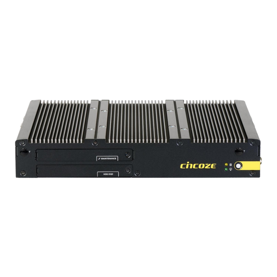
Page 13: Product Pictures
1x PCI or 1x PCIe Slot for Add-on Card Expansion: Max. Length 180mm including Bracket (with optional riser card) (For P2102E only) ⚫ Supports CDS Technology for Convertible Panel PC ⚫ Built-in Two 2W Internal Speakers P2102 Series | User Manual... -
Page 14: Hardware Specification
• 1x PCI or 1x PCIe x4 Expansion slot • Windows® 10 (with Optional Riser Card) (For P2102E only) • Linux: Supports by project • 2x Universal I/O Bracket (For P2102E only) • 1x Front Accessible SIM Socket • 4x Antenna Hole P2102 Series | User Manual... -
Page 15: System I/O
Used to connect to remote power on/off switch USB3.2 Gen2 Universal I/O Bracket (For P2102E) Used to connect to USB 3.2 Gen2/3.2 Used to expand I/O for Mini-PCIe module or Gen1/2.0/1.1 compatible devices PCI(e) card P2102 P2102E P2102 Series | User Manual... -
Page 16: Left
Press to decrease brightness of the screen Used to connect a speaker Mic-In Used to connect a microphone P2102 P2102E 1.6.5 Top VESA Mounting Hole These are mounting holes for VESA mount (75x75mm and 100x100mm) P2102 P2102E P2102 Series | User Manual... -
Page 17: Mechanical Dimension
1.7 Mechanical Dimension P2102 P2102E P2102 Series | User Manual... - Page 18 Chapter 2 Switches & Connectors P2102 Series | User Manual...
-
Page 19: Location Of Switches And Connectors
2.1 Location of Switches and Connectors 2.1.1 Top View 2.1.2 Bottom View P2102 Series | User Manual... -
Page 20: Switches And Connectors Definition
+5V/ +12V Power Output PWR_SW1 Remote Power On/Off Switch Connector SATA1, SATA2 SATA with Power Connector SIM1 SIM Card Socket SPK1, SPK2 Internal Speaker Connector USB2 USB 2.0 Port USB3.2 USB 3.2 Port VGA1 VGA Connector P2102 Series | User Manual... -
Page 21: Definition Of Switches
LED1: HDD / Power Access LED Status LED Type Status LED Color HDD Read/Write Yellow HDD LED No Operation Colorless POWER ON Green POWER LED POWER OFF Colorless Stand by Blinking Green PWR_SW2: System Power Button Switch Definition Push Power System P2102 Series | User Manual... - Page 22 ON (Default) ON (Default) COM1 Location Function DIP3 DIP4 0V(RI) ON (Default) ON (Default) COM2 Location Function DIP5 DIP6 0V(RI) ON (Default) ON (Default) COM3 Location Function DIP7 DIP8 0V(RI) ON (Default) ON (Default) COM4 P2102 Series | User Manual...
-
Page 23: Definition Of Connectors
2.4 Definition of Connectors COM1 / COM2 / COM3/ COM4: RS232 / RS422 / RS485 Connector Connector Type: 9-pin D-Sub RS422 / 485 Full RS485 Half RS232 Duplex Duplex Definition Definition Definition DATA - DATA + P2102 Series | User Manual... - Page 24 CN1: Mini PCI-Express Socket (Support mPCIE & SIM Module & USB) Definition Definition WAKE# 3.3V +1.5V SMB_CLK PETN0(USB3TN0) 1.5V SMB_DATA CLKREQ# PETP0(USB3TP0) SIM_VCC SIM_DATA USB_D- REFCLK- RESERVED SIM_CLK USB_D+ REFCLK+ RESERVED SIM_Reset 3.3V SIM_VPP 3.3V PERST# +1.5V PERN0(USB3RN0) 3.3V PERP0(USB3RP0) +3.3V P2102 Series | User Manual...
- Page 25 CN2: Mini PCI-Express Socket (Support mPCIE & USB) Definition Definition WAKE# 3.3V +1.5V SMB_CLK PETN0 1.5V SMB_DATA CLKREQ# PETP0 USB_D- REFCLK- USB_D+ REFCLK+ 3.3V 3.3V 3.3V PERST# +1.5V PERN0 +3.3VAUX PERP0 +3.3V P2102 Series | User Manual...
- Page 26 WGR_D1N PETP0 WTD1P/PETN1 RBI_DT PCM_SYNC/LPCRSTN WGR_D1N PETN0 PCM_IN CLINK_REST REF_CLK WTD0N/PETP1 PCM_OUT CLINK_DATA WGR_D0N PERP0 WTD0P/PERN1 CLINK_CLK WGR_D0P PERN0 COEX3 PEWAKE1# WTCLK/REFCLKP1 UART_WAKE COEX_TXD +3.3V WGR_CLKN REFCLKP0 WTCLK/REFCLKN1 BRI_RSP COEX_RXD +3.3V WGR_CLKP REFCLKN0 SUSCLK PERST0# P2102 Series | User Manual...
- Page 27 Connector Type: 1x4 4-pin Wafer, 2.0mm pitch Definition +12V PWR_SW1: Remote Power On/Off Switch Connector Connector Type: Terminal Block 1X2 2-pin, 3.5mm pitch Definition PWR_SW Do not apply power to this connector! This port is used to connect a SWITCH! P2102 Series | User Manual...
-
Page 28: Chapter 3 System Setup
Chapter 3 System Setup P2102 Series | User Manual... -
Page 29: Removing The Top Cover
1. Loosen the eight screws at front and rear panel. 2. Raise the edge of top cover (1), and raise the other side (2) subsequently to remove it from the chassis. 3. Place the top cover aside gently. P2102 Series | User Manual... -
Page 30: Installing A Half Size Mini Pcie Card
Use two screws provided on adapter bracket to fasten the card and bracket together. Tilt the Mini PCIe card at a 45-degree angle and insert it into the socket until the golden finger connector of the card seated firmly. 45° P2102 Series | User Manual... -
Page 31: Installing A Full Size Mini Pcie Card
1. Locate the Mini PCIe slot on the system board. 2. Tilt the Mini PCIe card at a 45-degree angle and insert it to the socket until the golden finger connector of the card seated firmly. P2102 Series | User Manual... -
Page 32: Installing A M.2 E Key Card
1. Locate the M.2 E Key slot on the system board. 2. Tilt the M.2 E Key card at a 45-degree angle and insert it to the socket until the golden finger connector of the card seated firmly. P2102 Series | User Manual... -
Page 33: Installing Antennas
3. Press the card down and secure it with 1 screw. 3.5 Installing Antennas 1. Remove the antenna rubber cover on front, left or right panel. 2. Penetrate the antenna jack through the hole. P2102 Series | User Manual... - Page 34 3. Put on the washer and fasten the nut with antenna jack. 4. Assemble the antenna and antenna jack together. Attach the RF connector at another end of the cable onto the card. P2102 Series | User Manual...
-
Page 35: Installing A So-Dimm Module
2. Tilt the memory module at a 45-degree angle, and insert it into SO-DIMM socket until the golden finger connector of the module is seated firmly. 3. Press down the memory module until retaining clips snap back in place. P2102 Series | User Manual... -
Page 36: Installing A Pci(E) Card
1. Loosen the two screws as indicated at rear panel. 2. Attach the PCI / PCIe Card Installation Kit on, and fasten the two screws back on rear panel to fix the Kit. 3. Loosen the screw as indicated to remove the PCI bracket. P2102 Series | User Manual... - Page 37 5. Align the notch of golden fingers of PCI(e) card with the expansion slot. Insert the card horizontally, and press the card straight down into the slot until it’s seated firmly. 6. Fasten the screw back to secure the PCI(e) expansion card. P2102 Series | User Manual...
- Page 38 7. Locate the retention module of PCI(e) expansion card. 8. Loosen the two screw as indicated to have the clamp arm slidable. P2102 Series | User Manual...
-
Page 39: Installing Thermal Pad Of Thermal Block
3.8 Installing Thermal Pad of Thermal Block 1. Place thermal pad on the top of CPU thermal block in order to provide a seamless contact with the body of chassis to create an efficient heat dissipation. P2102 Series | User Manual... -
Page 40: Installing The Top Cover
3.9 Installing the Top Cover 1. Put on the edge of top cover onto system, and the other side subsequently. 2. Fasten the eight screws at front and rear panel to secure the top cover. P2102 Series | User Manual... -
Page 41: Installing A Sata Hard Drive At Front Pane
3.10 Installing a SATA Hard Drive at Front Panel 1. Turn over the system to bottom side, and remove the screw. 2. Loosen the screw to remove the HDD bay cover bracket. P2102 Series | User Manual... - Page 42 3. Pull the rotating arm of HDD bracket outward as indicated. 4. Hold the rotating arm to pull out the HDD bracket. 5. Place the HDD bracket on screw-hole side of HDD. Use four screws provided to assemble HDD on the bracket. P2102 Series | User Manual...
- Page 43 HDD fully inserted into SATA slot. 7. Put back HDD bay cover at front panel, and fasten it with the screw. 8. Fasten the screw to secure the HDD bracket on the system chassis. P2102 Series | User Manual...
-
Page 44: Installing A Sata Hard Drive On Bottom Side
3.11 Installing a SATA hard drive on Bottom Side 1. Turn over the system to bottom side. Locate the cover of HDD compartment. P2102 Series | User Manual... - Page 45 2. Loosen the two screws, lift the cover, and then remove it. 3. Loosen three screws and take the HDD bracket out of HDD compartment. 4. Place the HDD bracket on screw-hole side of HDD. Use four screws provided to assemble HDD on the bracket. P2102 Series | User Manual...
- Page 46 5. Seat the HDD bracket into HDD compartment, and line up the connector of HDD with SATA slot, then push it until HDD is fully connected into slot. 6. Secure the HDD bracket with three screws. 7. Put back the cover and fasten the two screws. P2102 Series | User Manual...
-
Page 47: Installing A Sim Card
3.12 Installing a SIM Card 1. Loosen the screw to remove the Maintenance cover bracket. 2. Locate the SIM card slot. 3. Insert the SIM card. P2102 Series | User Manual... -
Page 48: Connecting With Cv Display Module
1. Prepare the mounting kit that accompanied with P2102 as shown. (including two mounting brackets and one screw pack) 2. Remove the six screws at left and right panel. 3. Assemble two mounting brackets by fastening six screws from the screws pack. P2102 Series | User Manual... - Page 49 5. Loosen two screws to remove the cover. The following photos indicates the male connector (on display module) and female connector (on P2102). 6. Place the P2102 on the display module through its display connector hole as indicated. P2102 Series | User Manual...
- Page 50 7. Align the mounting holes of P2102 with the screw holes of display module underneath. Then slide the PC2100 carefully as indicated to have P2102 and display module connected together. 8. Fasten six screws to secure P2102 on the display module. P2102 Series | User Manual...
-
Page 51: Wall Mount
M3-0.5x5) that came with the P2102. De-attach six rubber holes from the mounting brackets as indicated. 2. Remove the six screws at left and right panel. 3. Assemble two wall mount brackets by fastening six screws from the screws pack. P2102 Series | User Manual... - Page 52 The following picture indicates six wall mounting holes at each side. 4. Attach the P2102 to wall by fastening six screws through mounting holes at each side as illustrated. P2102 Series | User Manual...
-
Page 53: Din-Rail Mount Brackets
3.15 DIN-Rail Mount Brackets P2102 series offers DIN-Rail Mount that customer can install system on the DIN Rail. 1. Please refer to section 3.14 Wall Mount Brackets to install mounting bracket at both sides of system. 2. Fasten 2 DIN rail mounting clips to mounting brackets on both sides with provided 4 screws (with each screw size of T3x10.5) as illustrated. - Page 54 3. Clip the system into DIN rail as illustrated by the following steps. (1) Have lower end of mounting clip snaps into the DIN rail. (2) Press the system toward to have upper end of mounting clip snaps into the other side of DIN rail. P2102 Series | User Manual...
-
Page 55: Chapter 4 Bios Setup
Chapter 4 BIOS Setup P2102 Series | User Manual... -
Page 56: Bios Introduction
You can use arrow keys ( ↑↓ ) to highlight the field and press <Enter> to call up the sub-menu. Then you can use the control keys to enter values and move from field to field within a sub-menu. If you want to return to the main menu, just press the <Esc >. P2102 Series | User Manual... -
Page 57: Main Setup
Use arrow keys to move among the items and press <Enter> to accept or enter a sub-menu. 4.2.1 System Date Set the date. Please use <Tab> to switch between date elements. 4.2.2 System Time Set the time. Please use <Tab> to switch between time elements. P2102 Series | User Manual... -
Page 58: Advanced Setup
With virtualization, one computer system can function as multiple virtual systems. ■ Active Process Cores [All] Allows you to choose the number of active processor cores. Configuration options: [All] [1] [2] [3] P2102 Series | User Manual... -
Page 59: Pch-Fw Configuration
■ Intel AMT [Enabled] Allows you to enable or disable Intel® Active Management Technology BIOS execution. ■ Firmware Update Configuration ❑ ME FW Image Re-Flash [Disabled] Allows you to enable or disable ME firmware image re-flash function. P2102 Series | User Manual... -
Page 60: Acpi Settings
Allow you to enables or disables Security Device Support function. 4.3.4 ACPI Settings This item allows users to configure ACPI settings. ■ Enable ACPI Auto Configuration [Enabled] Enables or disables BIOS Advanced Configuration Power Interface® (ACPI) auto configuration. P2102 Series | User Manual... -
Page 61: F81866 Super Io Configuration
[S3 (suspend to RAM)]: Enables suspend to RAM state. 4.3.5 F81866 Super IO Configuration The screen allows users to select options for the Super IO configuration, and change the value of the selected option. ■ Serial Port 1~4 Configuration P2102 Series | User Manual... -
Page 62: Hardware Monitor
These items display the current status of all monitored hardware devices/ components such as voltages and temperatures. ■ Internal Smart Fan Function [Enabled] Enables or disables internal smart fan function. ■ Internal Smart Fan Configuration Allows users to setting internal smart fan parameters. P2102 Series | User Manual... -
Page 63: S5 Rtc Wake Settings
[Dynamic Time]: Set the increase time from current time to wake system. 4.3.8 Serial Port Console Redirection ■ Console Redirection [Disabled] These items allow users to enable or disable COM1, COM2, COM3, Com4 console redirection function. P2102 Series | User Manual... -
Page 64: Usb Configuration
■ XHCI Hand-off [Enabled] This item allows users to enable or disable XHCI (USB3.2) hand-off function. ■ USB Mass Storage Driver Support [Enabled] Enables or disables support for USB mass storage devices. 4.3.10 CSM Configuration P2102 Series | User Manual... -
Page 65: Nvme Configuration
The screen allows users to select options for the NVMe configuration, and change the value of the selected option. The options will show as the NVME Device is found. 4.3.12 Network Stack Configuration ■ Network Stack [Disabled] Enables or disables UEFI Network Stack. P2102 Series | User Manual... -
Page 66: Chipset Setup
4.4 Chipset Setup This section allows you to configure chipset related settings according to user’s preference. 4.4.1 System Agent (SA) Configuration ■ Memory Configuration This item displays detailed memory information in the system. P2102 Series | User Manual... -
Page 67: Pch-Io Configuration
This item allows users to enable or disable Internal Graphics. When set to [Auto], it will detect by BIOS. Configuration options: [Auto] [Disabled] [Enabled] ■ VT-d [Enabled] This item allows users to enable or disable Intel® Virtualization Technology for Directed I/O (VT-d) function. 4.4.2 PCH-IO Configuration P2102 Series | User Manual... - Page 68 ❑ PCI Express Root Port (PCIe1 Slot X4) ◼ PCI Express Root Port [Enabled] Allows you to enable or disable the PCI Express Port. ◼ PCIe Speed [Auto] Allows you to select PCI Express interface speed. Configuration options: [Auto] [Gen1] [Gen2] [Gen3]. P2102 Series | User Manual...
- Page 69 This item allows users to choose [AHCI] or [RAID] mode. ❑ Serial ATA Port 0 Port 0 [Enabled] Enables or disables SATA Port 0. ❑ Serial ATA Port 1 Port 1 [Enabled] Enables or disables SATA Port 1. ■ HD Audio Configuration P2102 Series | User Manual...
- Page 70 Allows you to specify which power state system will enter when power is resumed after a power failure (G3 state). [Always on]: Enters to power on state. [Always off]: Enters to power off state. [Keep last state]: Enters to the last power state before a power failure. P2102 Series | User Manual...
-
Page 71: Security Setup
User Password controls access to the system at boot and to the BIOS Setup utility. 4.5.3 Security Boot ❑ Secure Boot [Disabled] Enable or disable Secure Boot function. ❑ Secure Boot Mode [Standard] Allows you to select Secure Boor Mode. Configuration options: [Standard] [Custom]. P2102 Series | User Manual... -
Page 72: Boot Setup
Allows you to select the power-on state for keyboard NumLock. 4.6.3 Quiet Boot [Disabled] Allows you to enable or disable Quiet Boot function. 4.6.4 Fast Boot [Disabled] Allows you to enable or disable Fast Boot function. P2102 Series | User Manual... -
Page 73: Save & Exit
4.7.8 Save as User Defaults This item allows you to save the changes done so far as user defaults. 4.7.9 Restore User Defaults This item allows you to restore the user defaults to all the options. P2102 Series | User Manual... -
Page 74: Chapter 5 Product Application
Chapter 5 Product Application P2102 Series | User Manual... -
Page 75: Digital I/O (Dio) Application
5.1.1.1 Pins for Digital I/O Item Standard GPIO70 (Pin103) GPIO71 (Pin104) GPIO72 (Pin105) GPIO73 (Pin106) GPIO74 (Pin107) GPIO75 (Pin108) GPIO76 (Pin109) GPIO77 (Pin110) GPIO80 (Pin111) GPIO81 (Pin112) GPIO82 (Pin113) GPIO83 (Pin114) GPIO84 (Pin115) GPIO85 (Pin116) GPIO86 (Pin117) GPIO87 (Pin118) P2102 Series | User Manual... - Page 76 Following is an example to enable configuration and to disable configuration by using debug. -o 4e 87 -o 4e 87 (enable configuration) -o 4e aa (disable configuration) 5.1.1.3 Relative Registers To program the F81866A configuration registers, see the following configuration procedures. P2102 Series | User Manual...
- Page 77 P2102 Series | User Manual...
- Page 78 // Set (bit 0~7) = 0 to select GP 70~77 as Input mode. <Input Value> WriteByte(AddrPort, 0x82) // Select configuration register 82h ReadByte(DataPort, Value) // Read bit 0~7 (0xFF)= GP70 ~77 as High. <Leave the Extended Function Mode> WriteByte(AddrPort, 0xAA) P2102 Series | User Manual...
- Page 79 // Set (bit 0~7) = 1 to select GP 80 ~87 as Output mode. <Output Value> WriteByte(AddrPort, 0x89) // Select configuration register 89h WriteByte(DataPort, Value) // Set bit 0~7=(0/1) to output GP 80~87 as Low or High <Leave the Extended Function Mode> WriteByte(AddrPort, 0xAA) P2102 Series | User Manual...
- Page 80 // Select configuration register 60h WriteByte(DataPort, (ReadByte(DataPort) ǀ 0x03)) WriteByte(AddrPort, 0x61) // Select configuration register 61h WriteByte(DataPort, (ReadByte(DataPort) ǀ 0x20)) <Leave the Extended Function Mode> WriteByte(AddrPort, 0xAA) Cincoze default GPIO Port base address is 0xA00h P2102 Series | User Manual...
- Page 81 5.1.1.6 DATA Bit Table (DIO) = DI1 = DO1 = DI2 = DO2 = DI3 = DO3 = DI4 = DO4 = DI5 = DO5 = DI6 = DO6 = DI7 = DO7 = DI8 = DO8 P2102 Series | User Manual...
-
Page 82: P2102 Digital I/O (Dio) Hardware Specification
- DO Signal have to pull up resistor to XCOM+ for external device, the resistance will affect the pull up current - Signal High Level : Pull up resistor to XCOM+ - Signal Low Level : = XCOM- - Sink Current: 1A (Max) P2102 Series | User Manual... -
Page 83: P2102 Dio Connector Definition
5.2.1 P2102 DIO Connector Definition DIO-1/DIO-2 : Digital Input / Output Connector Connector Type: Terminal Block 2X10 10-pin, 3.5mm pitch Location Definition Location Definition DC INPUT DC INPUT DIO-1 DIO-2 P2102 Series | User Manual... - Page 84 Reference Input Circuit Reference Output Circuit P2102 Series | User Manual...
- Page 85 Chapter 6 Optional Modules & Accessories Pin Definitions and Settings P2102 Series | User Manual...
-
Page 86: Pin Definition And Settings Of Cfm-Ign Module
2 hours Reserved (0 second) Default setting of Pin1 to Pin4 is OFF/ON/ON/ON. 24V_12V_1: IGN Module Voltage Mode Setting Switch 12V / 24V Car Battery Switch Definition 24V Car Battery Input (Default) 12V Car Battery Input P2102 Series | User Manual... -
Page 87: Installing Cfm-Ign Module
6.2 Installing CFM-IGN Module Locate the power Ignition connector on system motherboard as indicated. Insert the female connector of power ignition board to the male connector on system motherboard. Fasten two screws to secure the power ignition board. P2102 Series | User Manual... -
Page 88: Installing Cfm-Poe Module
Before putting on the thermal block, please make sure the protective film on the Thermal Pad has been removed! 3. Paste the thermal pad onto the coil of the CFM-PoE module. Locate the PoE connector on system motherboard as indicated. P2102 Series | User Manual... - Page 89 Put on the PoE thermal block and fasten two screws to secure the PoE board. Before assembling the system’s chassis cover, please make sure the protective films on the Thermal Pads have been removed! P2102 Series | User Manual...
-
Page 90: Vesa Mount
To attach the panel PC to a VESA stand, please fasten eight screws as indicated to fix it on the stand. (Please refer to section 3.13 in this manual for how to attach PC2102 to CV/CS display module.) P2102 Series | User Manual... - Page 91 © 2019 Cincoze Co., Ltd. All rights reserved. The Cincoze logo is a registered trademark of Cincoze Co., Ltd. All other logos appearing in this catalog are the intellectual property of the respective company, product, or organization associated with the logo.
Need help?
Do you have a question about the P2102 Series and is the answer not in the manual?
Questions and answers