Table of Contents
Advertisement
Quick Links
One Technology Way • P.O. Box 9106 • Norwood, MA 02062-9106, U.S.A. • Tel: 781.329.4700 • Fax: 781.461.3113 • www.analog.com
FEATURES
Full featured evaluation board in conjunction with low
voltage digiPOT motherboard (EVAL-MB-LV-SDZ)
Various test circuits
Various ac/dc input signals
PC control via a separately purchased system demonstration
platform
(SDP-B
or SDP-S)
PC software for control
PACKAGE CONTENTS
EVAL-AD5142ADBZ
board
EVAL-MB-LV-SDZ motherboard
CD that includes
Self-installing software that allows users to control the
board and exercise all functions of the device
Electronic version of the
Electronic version of the
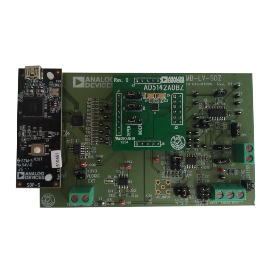
Figure 1. Digital Picture of Evaluation Board with Low Voltage DigiPOT Motherboard and System Demonstration Platform
PLEASE SEE THE LAST PAGE FOR AN IMPORTANT
WARNING AND LEGAL TERMS AND CONDITIONS.
Evaluating the
AD5142A
AD5142A
data sheet
UG-472
user guide
EVAL-AD5142ADBZ
Evaluation Board User Guide
Digital Potentiometer
GENERAL DESCRIPTION
This user guide describes the evaluation board for evaluating the
AD5142A—a quad-channel, 256-position, nonvolatile memory,
digital potentiometer. With versatile programmability, the
AD5142A
allows multiple modes of operation, including
read/write access in the RDAC and EEMEM registers,
increment/decrement of resistance, resistance changes in ±6 dB
scales, wiper setting readback, and extra EEMEM for storing
user-defined information, such as memory data for other
components or a lookup table.
The
AD5142A
supports a dual-supply ±2.25 V to ±2.75 V operation
and a single-supply 2.3 V to 5.5 V operation, making the device
suitable for battery-powered applications and many other appli-
cations. In addition, the
serial interface that operates in fast mode, allowing speeds of up to
400 kbps and supporting the selection of up to nine different I
addresses. The
or dual-supply mode and incorporates an internal power supply
from the USB.
Complete specifications for the
AD5142A
data sheet, which is available from Analog Devices, Inc.,
and should be consulted in conjunction with this user guide
when using the evaluation board.
WITH MOTHERBOARD AND
Rev. 0 | Page 1 of 20
AD5142A
uses a versatile I
EVAL-AD5142DBZ
can operate in single-supply
AD5142A
part can be found in the
SDP-S
UG-472
2
C-compatible
2
C
Advertisement
Table of Contents

Subscribe to Our Youtube Channel
Related Manuals for Analog Devices EVAL-AD5142ADBZ


Summary of Contents for Analog Devices EVAL-AD5142ADBZ
-
Page 1: Features
Complete specifications for the AD5142A part can be found in the AD5142A data sheet, which is available from Analog Devices, Inc., and should be consulted in conjunction with this user guide when using the evaluation board. EVAL-AD5142ADBZ WITH MOTHERBOARD AND SDP-S Figure 1. -
Page 2: Table Of Contents
Package Contents ................1 Installing the Software ..............8 General Description ................. 1 Software Operation ..............10 EVAL-AD5142ADBZ with Motherboard and SDP-S ....1 Evaluation Board Schematics and Artwork ........ 11 Revision History ................2 Motherboard ................11 Evaluation Board Hardware ............3 Daughter Board ................ -
Page 3: Evaluation Board Hardware
The EVAL-MB-LV-SDZ motherboard supports using single and Link No. Option dual power supplies. +3V3 EVAL-AD5142ADBZ evaluation board can be powered either 3.3 V from the SDP port or externally by the J1 and J2 connectors, as AGND described in Table 1. -
Page 4: Test Circuits
However, by using the R34 and R35 external resistors, the user can reduce the voltage of the voltage references. In this case, use EVAL-AD5142ADBZ and EVAL-MB-LV-SDZ incorporate the A1 and B1 test points to measure the voltage applied to the several test circuits to evaluate the performance of the AD5142A. - Page 5 Evaluation Board User Guide UG-472 AC Signal Attenuation Table 6. AC Signal Attenuation Link Options The RDAC can be used to attenuate an ac signal, which must be Maximum provided externally using the AC_INPUT connector, as shown Voltage AC Signal Supply Amplitude Link...
- Page 6 UG-472 Evaluation Board User Guide Signal Amplifier The inverting amplifier with linear gain is shown in Figure 6, and the gain is defined in Equation 5. The RDAC can be operated as an inverting or noninverting signal amplifier supporting linear or pseudologarithmic gains. Note that the input signal, V , must be negative.
- Page 7 Evaluation Board User Guide UG-472 Table 7. Amplifier Selection Link Options Linear Setting Amplifier Gain Gain Mode Enabled Link Label Noninverting Linear N-INV N-INV Pseudologarithmic N-INV N-INV Inverting Linear Pseudologarithmic Rev. 0 | Page 7 of 20...
-
Page 8: Evaluation Board Software
Figure 9. To run the program, do the following: Click Start > All Programs > Analog Devices > AD5142A > AD5142A Eval Board. To uninstall the program, click Rev. 0 | Page 8 of 20... - Page 9 Evaluation Board User Guide UG-472 Figure 9. EVAL-AD5142ADBZ Software Main Window Rev. 0 | Page 9 of 20...
-
Page 10: Software Operation
SOFTWARE OPERATION value in its respective block within the diagram. In addition, buttons are available that allow you to change the level of some The main window of the EVAL-AD5142ADBZ software has hardware pins. two tabs, Visual Mode and Manual Control. -
Page 11: Evaluation Board Schematics And Artwork
Evaluation Board User Guide UG-472 EVALUATION BOARD SCHEMATICS AND ARTWORK MOTHERBOARD Figure 11. SDP Connector and Power Supply Rev. 0 | Page 11 of 20... - Page 12 UG-472 Evaluation Board User Guide Figure 12. Schematic of Test Circuits Rev. 0 | Page 12 of 20...
- Page 13 Evaluation Board User Guide UG-472 Figure 13. Schematic of Connectors to Daughter Board Rev. 0 | Page 13 of 20...
- Page 14 UG-472 Evaluation Board User Guide Figure 14. Component Side View of Motherboard Figure 15. Component Placement Drawing of Motherboard Figure 16. Layer 2 Side PCB Drawing of Motherboard Rev. 0 | Page 14 of 20...
-
Page 15: Daughter Board
Evaluation Board User Guide UG-472 DAUGHTER BOARD Figure 17. Schematic of Daughter Board Rev. 0 | Page 15 of 20... - Page 16 UG-472 Evaluation Board User Guide Figure 18. Component Side View of Daughter Board Figure 19. Component Placement Drawing of Daughter Board Rev. 0 | Page 16 of 20...
- Page 17 Evaluation Board User Guide UG-472 Figure 20. Layer 2 Side PCB Drawing of Daughter Board Rev. 0 | Page 17 of 20...
-
Page 18: Ordering Information
UG-472 Evaluation Board User Guide ORDERING INFORMATION BILL OF MATERIALS Table 8. Motherboard Reference Designator Description Supplier /Part Number BUF-3, BUF-4, BUF-W1 2-pin (0.1" pitch) header and shorting shunt FEC 1022247 and 150411 A6, A7, A8 3-pin SIL header and shorting link FEC 1022248 and 150410 A5, A9, A10, A11, A12 6-pin (3 ×... - Page 19 Evaluation Board User Guide UG-472 Table 9. Daughter Board Reference Designator Description Supplier /Part Number 256-position digital potentiometer AD5142ABCPZ10 A1, A2, A3 3-pin SIL header and shorting link FEC 1022248 and 150410 C2, C4 6.3 V tantalum capacitor (Case A), 10 µF, ±20% FEC 1190107 C1, C3 50 V, X7R ceramic capacitor, 0.1 µF, ±10%...
- Page 20 By using the evaluation board discussed herein (together with any tools, components documentation or support materials, the “Evaluation Board”), you are agreeing to be bound by the terms and conditions set forth below (“Agreement”) unless you have purchased the Evaluation Board, in which case the Analog Devices Standard Terms and Conditions of Sale shall govern. Do not use the Evaluation Board until you have read and agreed to the Agreement.
Need help?
Do you have a question about the EVAL-AD5142ADBZ and is the answer not in the manual?
Questions and answers