Table of Contents
Advertisement
Quick Links
Advertisement
Table of Contents

Related Manuals for Bercomac VERSATILE 54


Summary of Contents for Bercomac VERSATILE 54
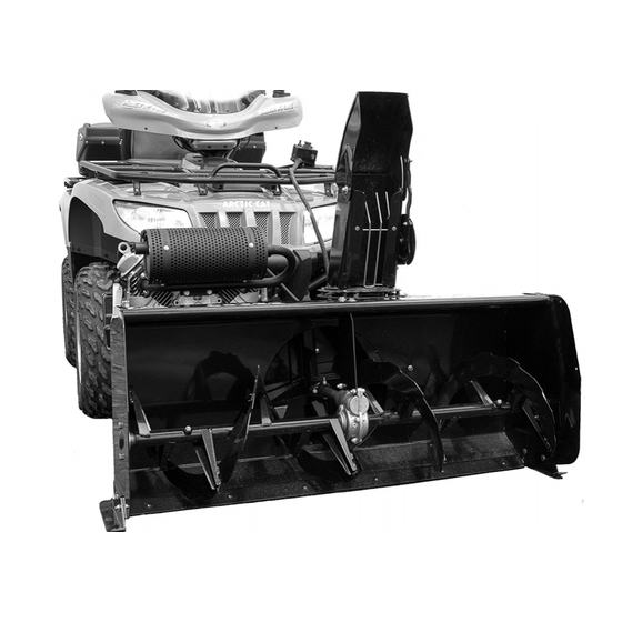
- Page 1 OWNER’S MANUAL Model Number 700460-2 BERCO VERSATILE 54" Snowbl ower ALL TERRAIN VEHICLES & UTILITY VEHICLES * ASSEMBLY * REPAIR PARTS * OPERATION * MAINTENANCE CAUTION: READ & FOLLOW ALL SAFETY RULES & INSTRUCTIONS BEFORE OPERATING YOUR EQUIPMENT *105223_EN* 105223_EN...
- Page 2 NOTE: All warranty work must be performed by an authorized dealer using original (manufacturer) replacement parts. NOTE: Bercomac reserves the right to change or improve the design of any part or accessory without assuming any obligation to modify any product previously manufactured.
-
Page 3: Table Of Contents
TABLE OF CONTENTS PAGE INTRODUCTION ..............................SAFETY PRECAUTIONS ............................SAFETY DECALS ..............................ASSEMBLY Tools Required ..........................Step 1: Snowblower Preparation ......................Step 2: Engine Installation ........................Step 3: Subframe Preparation ........................Step 4: Vehicle Preparation ........................Step 5: Control Box Installation ....................... Step 6: Final Adjustments ........................ -
Page 4: Introduction
INTRODUCTION TO THE PURCHASER This new accessory was carefully designed to give years of dependable service. This manual has been provided to assist in the safe operation and servicing of your attachment. NOTE: All photographs and illustrations in the manual may not necessarily depict the actual models or attachment, but are intended for reference only and are based on the latest product information available at the time of publication. -
Page 5: Safety Precautions
SAFETY PRECAUTIONS Careful operation is your best insurance against an accident. Read this section carefully before operating the vehicle and accessory. This accessory is capable of amputating hands and feet and throwing objects. Failure to observe the following safety instructions could result in serious injury. All operators, no matter how experienced they may be, should read this and other manuals related to the vehicle and accessory before operating. - Page 6 SAFETY PRECAUTIONS OPERATION: 14. Keep the accessory away from heat sources or flames. Do not put hands or feet near, under or inside rotating parts. MAINTENANCE AND STORAGE Exercise extreme caution when operating on or When cleaning, repairing or inspecting the vehicle crossing gravel drives, walks or roads.
-
Page 7: Safety Decals
SAFETY DECALS REPLACE IF DECALS ARE DAMAGED SEE PARTS BREAKDOWN FOR DECAL LOCATION Decal # 102125 Decal # 102126 Decal # 102128 Decal # 103951 Decal # 102553 Decal # 102127... -
Page 8: Assembly
ASSEMBLY IMPORTANT: TORQUE ALL BOLTS ACCORDING TO TORQUE SPECIFICATION TABLE (SEE TABLE CONTENTS) WHEN STATED: TIGHTEN FIRMLY. REFER PARTS BREAKDOWN SECTION FOR PART IDENTIFICATION. STEP 1 SNOWBLOWER PREPARATION: Overall view of snowblower TOOLS REQUIRED: 1 Ratchet 3 Sockets 7/16’’, 1/2’’, 9/16’’ 3 Wrenches, 7/16’’, 1/2’’, 9/16’’... - Page 9 ASSEMBLY Install the rotation ring (item 1) over opening (item 2) as shown and align the notches. Place the chute (item 3) (facing the rear) and clip the back over the rotation ring then turn the chute towards the front to lock into place. Install chute Install two carriage bolts 1/4"...
-
Page 10: Step 2: Engine Installation
ASSEMBLY STEP 2 ENGINE INSTALLATION: IMPORTANT: We recommend using a 15 to 23 hp. engine on this snowblower with a 1’’ horizontal shaft. HERE ARE A FEW SUGGESTION OF ENGINES THAT HAVE BEEN TESTED. Tested engines Honda engines Kohler engine 18 hp 20 hp 20 hp... - Page 11 ASSEMBLY MOTOR INSTALLATION For engines with an electric starter, it is necessary to connect the vehicle's battery to the starter on the snowblower engine. You must obtain option #700476 to allow this connection. Remove the belt guard (item 3) by removing the three 1/4"x 1/2"...
- Page 12 ASSEMBLY AXIS AXIS Choose the right pulley (#104833 = 1" or #104839 = 1 AXIS 1/8") (item 1) according to the diameter of the engine’s shaft. Install the pulley (Fig. 1, item 1) on the engine shaft as shown (hub towards the engine) with a 1/4" x 1/4" x 1 3/4"...
-
Page 13: Step 3: Subframe Preparation
ASSEMBLY STEP 3 SUBFRAME PREPARATION: Determine according to the height of the vehicle which set of holes to use to assemble the wheel support (item 1) to the subframe (item 2). The subframe must be parallel with the ground when the subframe is installed under the vehicle. - Page 14 ASSEMBLY You have seven different positions on the adjustment tube (item 1) (the adjustment tube can be inverted) to adjust the length of the subframe. To choose the right adjustment, insert the adjustment tube (item 1) into the subframe (item 2) and insert the rear bracket (item 3) on the adjustment tube..
-
Page 15: Step 4: Vehicle Preparation
ASSEMBLY STEP 4 VEHICLE PREPARATION: NOTE: A 1 7/8” or 50 mm tow hitch ball is required. Choose among the three different options to prepare your vehicle (A, B, C). A) Install the lift strap (item 1) by looping it around the suspension arm (as shown) on the vehicle. -
Page 16: Step 5: Control Box Installation
ASSEMBLY STEP 5 Three possible positions CONTROL BOX INSTALLATION: Choose between the three different ways of securing the control box support (item 1). Use two hex bolts 1/4” x 1/2’’ or 1 1/2” (items 6 or 2), support brackets (item 4), spacers (item 3) and flange nuts. - Page 17 ASSEMBLY IMPORTANT: The control box is equipped with a red emergency switch. Push down on this button if it becomes necessary to stop the engine quickly. ENGINE CIRCUIT BRE AKER INSTALLATION: (EMERGENCY SWITCH WIRE): Find the wire (item 1) on the engine that supplies the engine’s booster coil and disconnect it.
- Page 18 ASSEMBLY IMPORTANT: Take the time to familiarize yourself with the location of the switches and with their use. NOTE: If the switches don’t match the right controls, reconnect the connectors with the right motors. Pay particular attention to the switch for the belt tensioner (item 4).This switch must be held in position for a few seconds in order to activate or deactivate the lever of the belt tensioner.
-
Page 19: Step 6: Final Adjustments
ASSEMBLY STEP 6 WARNING FINAL ADJUSTMENTS TO PREVENT INJURIES: DANGER Start the engine, engage and disengage the clutch to be sure if functions normally. Make sure the emergency switch is working Never let the snowblower motor run without the perfectly. Make sure all the controls are working belt guard in place. - Page 20 ASSEMBLY DANGER: It is the reponsibility of the person who installs the engine and the controls to make sure that the engaging system works well and that the snowblower disengages effectivly at all times. It is imperative to make the necessary adjustments if applicable.
-
Page 21: Operation
OPERATION WARNING WARNING Read the vehicle's owner’s manual carefully. Be PREVENT INJURIES MORE thoroughly familiar with the controls & proper TRACTION WHEN USING SNOWBLOWER: use of the attachment. Know how to stop the unit -Do not drive faster than 3 km/hr (2 m/hr) with snowblower on the ground. -
Page 22: Maintenance & Dismounting
MAINTENANCE & DISMOUNTING To avoid damage to the snowblower: WARNING Use only the original shear bolts (grooved bolts). #104000 in bags of 10 for the augers. #103999 in bags of 10 for the fan. TO PREVENT INJURIES: The use of any other shear bolt will not insure any Stop the snowblower motor. -
Page 23: Belt Replacement
BELT REPLACEMENT CAUTION Never use the snowblower without the belt guard. BELT REPLACEMENT: For belt part number, refer to parts breakdown section for parts identification. a) Remove the belt guard (item 1) by removing the threes hex bolts 1/4" x 1/2" (item 2). b) Remove the tension from the belt by pushing on the switch for the belt tensionner. -
Page 24: Troubleshooting
TROUBLESHOOTING (For identification, see the parts breakdown) PROBLEM POSSIBLE CAUSES CORRECTIVE ACTION Snowblower vibrates Damaged pulley. Replace pulley. abnormally noisy. Damaged bearing. Replace bearing. Damaged fan or sections of auger. Dismount & repair or replace fan. Auger stopped turning. Shear bolt broken. Replace shear bolt. -
Page 25: Torque Specification Table
TORQUE SPECIFICATION TABLE GENERAL TORQUE SPECIFICATION TABLE USE THE FOLLOWING TORQUES WHEN SPECIAL TORQUES ARE NOT GIVEN NOTE: These values apply to fasteners as received from supplier, dry or when lubricated with normal oil. They do not apply if special graphited or moly disulphide greases or other extreme pressure lubricants are used. This applies to both UNF and UNC threads. -
Page 26: Rotation System With Chute
PARTS BREAKDOWN ROTATION SYSTEM WITH CHUTE... - Page 27 PARTS LIST ROTATION SYSTEM WITH CHUTE Ref. Qty. Part # English description Description française Réf. Qté. Pièce # 1 Chute Goulotte 103936 2 Bracket Support 103971 3 Reinforcement plate Plaque de renforcement 103972 4 Spacer Espaceur 103368 5 Rotation ring Anneau de rotation 103974 6 Hex.
-
Page 28: Subframe
PARTS BREAKDOWN SUBFRAME... - Page 29 PARTS LIST SUBFRAME Ref. Qty. Part # English description Description française Réf. Qté. Pièce # Subframe Sous-châssis 104957 Wheel support Support de roue 104770 Rear bracket Fixation arrière 104956 Hitch support Support d'attache 104958 Adjustment tube Tube d'ajustement 104959 Hitch Attache 104639 Hitch ball support...
-
Page 30: Snowblower
PARTS BREAKDOWN SNOWBLOWER... - Page 31 PARTS LIST SNOWBLOWER Ref. Qty. Part # English description Description française Réf. Qté. Pièce # Frame 54" Châssis 54" 104780 Hitch Attache 104781 Engine support Support-moteur 104782 Lever Levier 104783 Pulley 3.15" with set screw Poulie 3.15" avec vis pression 104833 Pulley 3.55"...
- Page 32 PARTS LIST SNOWBLOWER Ref. Qty. Part # English description Description française Réf. Qté. Pièce # Oil lite bushing Coussinet imprégné d'huile 102784 Cutting edge 54" Racloir 54" 104427 Skid shoe Patin 103188 Key 1/4" x 1/4" x 1 3/4" Clé 1/4" x 1/4" x 1 3/4" 102327 Flangette Flangette...
- Page 33 PARTS LIST SNOWBLOWER Ref. Qty. Part # English description Description française Réf. Qté. Pièce # Hex. bolt 1/4" n.c. x 1/2" Boulon hex. 1/4" n.c. x 1/2" Flange nut 1/4" n.c. Écrou à bride 1/4" n.c. Hex. bolt 3/8" n.c. x 1 1/4" Boulon hex.
-
Page 34: Options & Accessories
OPTIONS & ACCESSORIES #700269 #700461 LIFT CONNECTION KIT #700260 EXTENSION AND Reduces the effort and the speed SNOW DRIFT CUTTER SIDE WIDENING ANGLES KIT Slices through high snow drifts to facilitate and required by the winch to lift the Widens the snowblower to 60" increase snow intake. - Page 35 NOTES _____________________________________________________________________________________________ _____________________________________________________________________________________________ _____________________________________________________________________________________________ _____________________________________________________________________________________________ _____________________________________________________________________________________________ _____________________________________________________________________________________________ _____________________________________________________________________________________________ _____________________________________________________________________________________________ _____________________________________________________________________________________________ _____________________________________________________________________________________________ _____________________________________________________________________________________________ _____________________________________________________________________________________________ _____________________________________________________________________________________________ _____________________________________________________________________________________________ _____________________________________________________________________________________________ _____________________________________________________________________________________________ _____________________________________________________________________________________________ _____________________________________________________________________________________________ _____________________________________________________________________________________________ _____________________________________________________________________________________________ _____________________________________________________________________________________________ _____________________________________________________________________________________________ _____________________________________________________________________________________________ _____________________________________________________________________________________________...
- Page 36 WHEN PERFORMANCE & DEPENDABILITY ARE NON NEGOTIABLE ! Ber comac Limitée 92, For tin Nor th, Adstock, Quebec, Canada, G0N 1S0 WWW.BERCOMAC.COM PRINTED IN CANADA...
Need help?
Do you have a question about the VERSATILE 54 and is the answer not in the manual?
Questions and answers