Table of Contents
Advertisement
OWNER'S MANUAL
Model Number
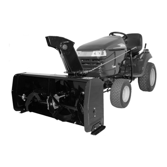
700576 Snowblower 44''
Northeast 2 Stage Snowblower 44'' with Electric Lift
for
THE MAJORITY OF TRACTORS BY H.O.P. (2006 AND AFTER)
CRAFTSMAN, HUSQVARNA, ARIENS, DIXON, POULAN, WEEDEATER
CAUTION:
READ & FOLLOW ALL SAFETY RULES & INSTRUCTIONS BEFORE
OPERATING YOUR EQUIPMENT
*105806_EN*
105806_EN
K-09
1
Advertisement
Table of Contents

Related Manuals for Bercomac Northeast 700576


Summary of Contents for Bercomac Northeast 700576
- Page 1 OWNER’S MANUAL Model Number 700576 Snowblower 44’’ Northeast 2 Stage Snowblower 44’’ with Electric Lift THE MAJORITY OF TRACTORS BY H.O.P. (2006 AND AFTER) CRAFTSMAN, HUSQVARNA, ARIENS, DIXON, POULAN, WEEDEATER CAUTION: READ & FOLLOW ALL SAFETY RULES & INSTRUCTIONS BEFORE...
- Page 2 NOTE: All warranty work must be performed by an authorized dealer using original (manufacturer) replacement parts. NOTE: Bercomac reserves the right to change or improve the design of any part or accessory without assuming any obligation to modify any product previously manufactured.
-
Page 3: Table Of Contents
TABLE OF CONTENTS PAGE INTRODUCTION ..............................SAFETY PRECAUTIONS ............................SAFETY DECALS ..............................ASSEMBLY Tools Required ............................Step 1: Subframe Installation ........................Step 2: Installation of the Control Assembly....................Step 3: Drive Mechanism Installation ...................... Step 4: Snowblower Preparation ......................Step 5: Snowblower Installation ....................... Verify Tire Pressure ........................ -
Page 4: Introduction
INTRODUCTION TO THE PURCHASER This new accessory was carefully designed to give years of dependable service. This manual has been provided to assist in the safe operation and servicing of your attachment. NOTE: All photographs and illustrations in the manual may not necessarily depict the actual models or attachment, but are intended for reference only and are based on the latest product information available at the time of publication. -
Page 5: Safety Precautions
SAFETY PRECAUTIONS Careful operation is your best insurance against an accident. Read this section carefully before operating the vehicle and accessory. This accessory is capable of amputating hands and feet and throwing objects. Failure to observe the following safety instructions could result in serious injury. All operators, no matter how experienced they may be, should read this and other manuals related to the vehicle and accessory before operating. - Page 6 SAFETY PRECAUTIONS OPERATION: 13. Keep the accessory away from heat sources or flames. Do not put hands or feet near, under or inside rotating parts. MAINTENANCE AND STORAGE Exercise extreme caution when operating on or When cleaning, repairing or inspecting the vehicle crossing gravel drives, walks or roads.
-
Page 7: Safety Decals
SAFETY DECALS REPLACE IF DECALS ARE DAMAGED SEE PARTS BREAKDOWN FOR DECAL LOCATION DECAL #105130 DECAL #105126 To avoid serious injury: Keep hands, feet & clothing away from rotating auger while engine is running. Before installing or using: Locate, read and make sure to understand all of the DECAL #105127 owner’s manual. -
Page 8: Assembly
ASSEMBLY IMPORTANT: TORQUE ALL BOLTS ACCORDING TOOLS REQUIRED: TO TORQUE SPECIFICATION TABLE WHEN STATED: TIGHTEN FIRMLY. Wrenches: 5/16, 7/16, 9/16, 1/2, 10mm THE WINCH KIT IS TO BE USED ONLY TO LIFT Ratchet BERCO ACCESSORIES, ANY OTHER USE MAY Sockets: 9/16, 1/2 CAUSE DAMAGE TO THE VEHICLE. - Page 9 ASSEMBLY Install the female hitch (item 1) # Item Description Action Female hitch Install between the two supports. Hex bolt 3/8 x 1’’ Insert as shown. (qty 4) Flange nut 3/8’’ Tighten all the nuts (qty 4) firmly. Install the female hitch between the two supports Install the spring (item 1) # Item Description...
- Page 10 ASSEMBLY NOTE: Use these same instructions for both sides of tractor. Manual Clutch: Install the new belt guides (item A) that are included with the drive mechanism on the bottom carriage bolt (item 1). Place a 1/2’’ flat washer (items B & C) over the belt guide and the top carriage bolt.
-
Page 11: Step 2: Installation Of The Control Assembly
ASSEMBLY STEP 2: INSTALLATION OF THE CONTROL ASSEMBLY Install the relay (item 1). Description Action Item Relay Install in an appropriate area. Metal screw Secure relay in place. #12 x 3/4’’ (qty 4) Nylon tie wrap 8’’ See * (qty 4) *If necessary use the nylon tie wraps to secure the relay in place. - Page 12 ASSEMBLY CONNECTING THE WIRES NOTE:The posts on the relay are identified by numbers. (1-2-3-4). Install the wires from the winch on the posts of the relay. Red wire (+) on post #3. Black wire (-) on post #4. Connect the red wire from the winch (limit switch) with the green wire from the relay.
- Page 13 ASSEMBLY CAUTION FOR YOUR SECURITY: Read and follow the safety precautions for the battery in the vehicle’s manual. CONNECT THE WIRES ON THE BATTERY: Connect the wires from the relay to the vehicle’s battery. The red wire (+) on the positive post of the battery (item 1).
-
Page 14: Step 3: Drive Mechanism Installation
ASSEMBLY STEP 3: WARNING DRIVE MECHANISM INSTALLATION: TO PREVENT INJURIES: It is the person who installs the drive mechanism WARNING responsibility to make sure that when the clutch is disengaged that all moving parts stop. TO PREVENT INJURIES: For more information, do not hesitate to contact Stop the motor. - Page 15 ASSEMBLY Install the drive mechanism (item 1). # Item Description Action The front end of drive Hook on the pins. mechanism The back end of Install between the drive mechanism supports. Insert as shown. Hair pin Secure the pin. Install the drive mechanism For tractors with Electric Clutch: Install the belt on the engine pulley of the vehicle.
- Page 16 ASSEMBLY VERIFICATION OF THE BELT AND PULLEY ALIGNMENT: WARNING TO PREVENT INJURIES: do this verification when the engine of the vehicle is not running. IMPORTANT: Adjust the height of the three supports (items 1, 2 and 3) to make sure the drive mechanism pulley (item 4) is aligned with the engine pulley (item 5) more or less 1/8’’.
-
Page 17: Step 4: Snowblower Preparation
ASSEMBLY Overall view STEP 4: SNOWBLOWER PREPARATION: Refer parts breakdown section parts identification. Install the chute (item 3). Item # Description Action Flange nut (qty 2) Loosen to last threads. Rotation ring Install over opening. Chute Place as shown, turn to lock into place. -
Page 18: Step 5: Snowblower Installation
INSTALLATION STEP 5 SNOWBLOWER INSTALLATION: You must install the subframe and drive mechanism before continuing to install the snowblower. WARNING TO PREVENT INJURIES: Stop the motor. Apply parking brake. Remove the ignition key. Disconnect the wire from the spark plug(s) and keep away from spark plug(s) to prevent accidental starting. -
Page 19: Verify Tire Pressure
INSTALLATION Install handle (item 2). Item # Description Action Hair pin Remove from handle. Handle Insert in handle support. Hook Insert in handle and secure with hair pin. Install handle VERIFY SKID SHOE ADJUSTMENT: LEVEL PAVED SURFACE: Adjust skid shoes to allow 3/16"... -
Page 20: Operation
OPERATION WARNING WARNING PREVENT INJURIES MORE Read the tractor Owner’s Manual carefully. Be TRACTION WHEN USING AN ATTACHMENT: thoroughly familiar with the controls & proper -Rear counterweight of 100 lbs. minimum is use of the attachment. Know how to stop the required to counterbalance the attachment’s attachment quickly weight. -
Page 21: Adjustments
MAINTENANCE MAINTENANCE Refer to parts breakdown section for parts AUGERS SHEAR BOLT identification. REPLACEMENT WARNING Shear bolts are to be considered a preventive measure and not an assured protection. Operator vigilance is required. Thoroughly inspect the areas TO PREVENT INJURIES: where the snowblower is to be used and remove all Stop the motor. -
Page 22: Belt Installation, Adjustment, And Replacement
MAINTENANCE BELT INSTALLATION, ADJUSTMENT, AND REPLACEMENT: WARNING The belt tension arm is spring loaded & needs to be held firmly while displacing to prevent injury IMPORTANT: When aligning or replacing the snowblower pulley (item 4), you must clean the parts and use ‘’Lock-tite’’ 2760 on the key and the set screws. -
Page 23: Replacement Of One Or Two Sections Of The Auger And / Or Gear Box
REPLACEMENT OF ONE OR TWO SECTIONS OF THE AUGER AND / OR GEAR BOX For belt part numbers, refer to snowblower parts breakdown section for parts identification Snowblower must be detached & disconnected from the tractor to replace the auger or the gear box. -
Page 24: Dismounting & Storage
DISMOUNTING & STORAGE STORAGE SNOWBLOWER DISMOUNTING a) Clean snowblower thoroughly and repaint all CAUTION parts from which paint has worn. b) List the replacement parts that will be needed to The belt tension is spring loaded & needs to be be replaced before the next season. -
Page 25: Troubleshooting
TROUBLESHOOTING * Please refer to parts breakdown section for parts identification. PROBLEM POSSIBLE CAUSES CORRECTIVE ACTION One section or both sections of the Shear bolts are probably broken. Replace shear bolts. auger stops turning. Fan stops turning. Shear bolt is probably broken. Replace shear bolts. - Page 26 TROUBLESHOOTING * Please refer to parts breakdown section for parts identification. PROBLEM POSSIBLE CAUSES CORRECTIVE ACTION Snowblower does not raise evenly. Tire pressure uneven from one side Verify and adjust tire pressure: to another. Front tires: 14 to 15 psi Rear tires: 7 to 8 psi Snowblower vibrates or is Damaged pulley.
- Page 27 MAINTENANCE TROUBLESHOOTING * Please refer to parts breakdown section in subframe manual for parts identification. HOW TO KNOW POINTS TO CHECK Poor connections. Recheck wiring with the owner's manual. HI/LOW voltage tester does not work. Connect it on battery posts (+ and -) of a functional battery. If there is no light, the tester is damaged.
-
Page 28: Chute
************************* PARTS BREAKDOWN CHUTE... -
Page 29: Parts List
PARTS LIST CHUTE WITH ROTATION SYSTEM Ref. Qty. Part # English description Description française Réf. Qté. Pièce # Chute Goulotte 103936 Rotation ring Anneau de rotation 103943 Nylon flat washer 7/16" Rondelle plate de nylon 7/16" 102011 Nylon flat washer 11/32" Rondelle plate de nylon 11/32"... -
Page 30: Snowblower
PARTS BREAKDOWN SNOWBLOWER... - Page 31 PARTS LIST SNOWBLOWER Ref. Qty. Part # English description Description française Réf. Qté. Pièce # Frame 44" Châssis 44" 104851 Shear plate Plaque de cisaillement 103933 Éventail 103932 Flangette Flangette 102213 Bearing with set screw Roulement à billes avec vis à pression 102755 Auger 44"...
- Page 32 PARTS LIST SNOWBLOWER Ref. Qty. Part # English description Description française Réf. Qté. Pièce # Belt guard Garde-courroie 104855 Knob Bouton 103027 Gear box support Support de boîte d'engrenage 104746 Oil lite bushing Coussinet imprégné d'huile 102784 Shear bolt / N.I.L.N. (fan) pkg-10 Boulon de séc./ É.G.N.
- Page 33 PARTS LIST SNOWBLOWER Ref. Qty. Part # English description Description française Réf. Qté. Pièce # Hex. bolt 7/16" n.c. x 1 1/4" Boulon hex. 7/16" n.c. x 1 1/4" Hex. bolt 1/2" n.c. x 1 3/4" Boulon hex. 1/2" n.c. x 1 3/4" Carriage bolt 1/4"...
-
Page 34: Northeast Drive Mechanism
PARTS BREAKDOWN NORTHEAST DRIVE MECHANISM... - Page 35 PARTS LIST NORTHEAST DRIVE MECHANISM Ref. Qty. Part # English description Description française Réf. Qté. Pièce # Drive frame Châssis d'entraînement 104838 Drive frame support Support du châssis d'entraînement 104840 Adjustment rod Tige d'ajustement 104841 Right support Support droit 104842 Left support Support gauche 104843...
-
Page 36: Subframe
PARTS BREAKDOWN SUBFRAME... - Page 37 PARTS LIST SUBFRAME Ref. Qty. Part # English description Description française Réf. Qté. Pièce # Female hitch Attache femelle 104817 Latch Loquet 104818 Cab support Support de cabine 104819 Control base Base du contrôle 104820 Control support Support du contrôle 104821 Support Support...
- Page 38 PARTS LIST SUBFRAME Ref. Qty. Part # English description Description française Réf. Qté. Pièce # Relay Relais 105257 Instant connector Connecteur instantané 105152 Push plate Plaque de poussée 105150 Limit switch Commutateur de fin de course 105136 Hi/low voltage tester Testeur de haute/basse tension 105151 Breaker...
-
Page 39: Torque Specification Table
TORQUE SPECIFICATION TABLE GENERAL TORQUE SPECIFICATION TABLE USE THE FOLLOWING TORQUES WHEN SPECIAL TORQUES ARE NOT GIVEN NOTE: These values apply to fasteners as received from supplier, dry or when lubricated with normal oil. They do not apply if special graphited or moly disulphide greases or other extreme pressure lubricants are used. This applies to both UNF and UNC threads. -
Page 40: Options & Attachments
OPTIONS OPTIONS & ATTACHMENTS ROTARY BROOM #700380 with nylon brush COUNTERWEIGHT /#700381 with polypropylene brush. Model # 700246-5 SNOW BLADE #700463 Fits on same subframe as Required for safety and traction. Mounts on the same subframe as the snowblower or utility blade. Counter-balances weight of snowblower &... - Page 41 NOTES _____________________________________________________________________________________________ _____________________________________________________________________________________________ _____________________________________________________________________________________________ _____________________________________________________________________________________________ _____________________________________________________________________________________________ _____________________________________________________________________________________________ _____________________________________________________________________________________________ _____________________________________________________________________________________________ _____________________________________________________________________________________________ _____________________________________________________________________________________________ _____________________________________________________________________________________________ _____________________________________________________________________________________________ _____________________________________________________________________________________________ _____________________________________________________________________________________________ _____________________________________________________________________________________________ _____________________________________________________________________________________________ _____________________________________________________________________________________________ _____________________________________________________________________________________________ _____________________________________________________________________________________________ _____________________________________________________________________________________________ _____________________________________________________________________________________________ _____________________________________________________________________________________________ _____________________________________________________________________________________________ _____________________________________________________________________________________________...
- Page 42 NOTES _____________________________________________________________________________________________ _____________________________________________________________________________________________ _____________________________________________________________________________________________ _____________________________________________________________________________________________ _____________________________________________________________________________________________ _____________________________________________________________________________________________ _____________________________________________________________________________________________ _____________________________________________________________________________________________ _____________________________________________________________________________________________ _____________________________________________________________________________________________ _____________________________________________________________________________________________ _____________________________________________________________________________________________ _____________________________________________________________________________________________ _____________________________________________________________________________________________ _____________________________________________________________________________________________ _____________________________________________________________________________________________ _____________________________________________________________________________________________ _____________________________________________________________________________________________ _____________________________________________________________________________________________ _____________________________________________________________________________________________ _____________________________________________________________________________________________ _____________________________________________________________________________________________ _____________________________________________________________________________________________ _____________________________________________________________________________________________...
- Page 43 NOTES _____________________________________________________________________________________________ _____________________________________________________________________________________________ _____________________________________________________________________________________________ _____________________________________________________________________________________________ _____________________________________________________________________________________________ _____________________________________________________________________________________________ _____________________________________________________________________________________________ _____________________________________________________________________________________________ _____________________________________________________________________________________________ _____________________________________________________________________________________________ _____________________________________________________________________________________________ _____________________________________________________________________________________________ _____________________________________________________________________________________________ _____________________________________________________________________________________________ _____________________________________________________________________________________________ _____________________________________________________________________________________________ _____________________________________________________________________________________________ _____________________________________________________________________________________________ _____________________________________________________________________________________________ _____________________________________________________________________________________________ _____________________________________________________________________________________________ _____________________________________________________________________________________________ _____________________________________________________________________________________________ _____________________________________________________________________________________________...
- Page 44 Toll free phone: 888-263-9609 (parts are available on order) FOR TECHNICAL SUPPORT OR ANY OTHER INFORMATION : Contact Bercomac Limitée (Monday to Friday) 8:00 to 5:00 pm eastern time • Email: technicalsupport@bercomac.com • Toll free: 877-772-3726, ask for extension: #2299...
Need help?
Do you have a question about the Northeast 700576 and is the answer not in the manual?
Questions and answers