Table of Contents
Advertisement
Quick Links
Advertisement
Table of Contents

Related Manuals for Bercomac 700533-1


Summary of Contents for Bercomac 700533-1
- Page 1 OWNER’S MANUAL Model Number 700533-1 66’’ Snowblower BERCO 66’’ Nordic Snowblower ZERO TURN MOWERS * ASSEMBLY * REPAIR PARTS * OPERATION * MAINTENANCE CAUTION: READ & FOLLOW ALL SAFETY RULES & INSTRUCTIONS BEFORE OPERATING YOUR EQUIPMENT *105944_en* 105944_EN K-12...
- Page 2 NOTE: All warranty work must be performed by an authorized dealer using original (manufacturer) replacement parts. NOTE: Bercomac reserves the right to change or improve the design of any part or accessory without assuming any obligation to modify any product previously manufactured.
-
Page 3: Table Of Contents
TABLE OF CONTENTS PAGE INTRODUCTION ..............................SAFETY PRECAUTIONS ............................SAFETY DECALS ..............................ASSEMBLY Tools Required ............................Step 1: Snowblower Preparation ....................... Step 2: Snowblower Installation ........................ Step 3: Control Box Installation ......................... Step 4: Skid Shoe Adjustment and Installation of the Spring ..............OPERATION Operating the Snowblower ........................ -
Page 4: Introduction
INTRODUCTION TO THE PURCHASER This new accessory was carefully designed to give years of dependable service. This manual has been provided to assist in the safe operation and servicing of your attachment. NOTE: All photographs and illustrations in the manual may not necessarily depict the actual models or attachment, but are intended for reference only and are based on the latest product information available at the time of publication. -
Page 5: Safety Precautions
SAFETY PRECAUTIONS Careful operation is your best insurance against an accident. Read this section carefully before operating the vehicle and accessory. This accessory is capable of amputating hands and feet and throwing objects. Failure to observe the following safety instructions could result in serious injury. All operators, no matter how experienced they may be, should read this and other manuals related to the vehicle and accessory before operating. - Page 6 SAFETY PRECAUTIONS OPERATION: 13. Keep the accessory away from heat sources or flames. Do not put hands or feet near, under or inside rotating parts. MAINTENANCE AND STORAGE Exercise extreme caution when operating on or When cleaning, repairing or inspecting the vehicle crossing gravel drives, walks or roads.
-
Page 7: Safety Decals
SAFETY DECALS REPLACE IF DECALS ARE DAMAGED SEE PARTS BREAKDOWN FOR DECAL LOCATION DECAL #105126 DECAL #105130 To avoid serious injury: Before installing or using: Keep hands, feet & clothing away from rotating auger Locate, read and make sure to understand all of the while engine is running. -
Page 8: Assembly
ASSEMBLY IMPORTANT: TORQUE ALL BOLTS ACCORDING TO TORQUE SPECIFICATION TABLE (SEE TABLE CONTENTS) WHEN STATED: TIGHTEN FIRMLY. REFER PARTS BREAKDOWN SECTION FOR PART IDENTIFICATION. TOOLS REQUIRED: Wrench: 7/16’’ Socket: 7/16’’ Screwdriver No.2 Pliers Overall view of snowblower Allen Key 1/8’’ STEP 1 SNOWBLOWER PREPARATION: Refer... - Page 9 ASSEMBLY Install the chute (item 1). # Item Description Action Chute Place the chute on the nylon rotation ring. Turn the chute to make sure it turns freely. Place the chute at 45° angle as shown. Hex bolt Insert under the 1/4’’...
-
Page 10: Step 2: Snowblower Installation
INSTALLATION STEP 2 SNOWBLOWER INSTALLATION: You must install the subframe and drive mechanism before continuing to install the snowblower. WARNING TO PREVENT INJURIES: Stop the motor. Apply parking brake. Remove the ignition key. Disconnect the wire from the spark plug(s) and keep away from spark plug(s) to prevent accidental starting. -
Page 11: Step 3: Control Box Installation
ASSEMBLY STEP 3 CONTROL BOX INSTALLATION: NOTE: Install the control box in this place only if the threads on the control panel are made of metal. Remove the two existing screws from the place where the control box will be installed. (Can be installed on the side of the control panel according to the model of the tractor). - Page 12 ASSEMBLY Turn the chute to its maximum towards the right. Secure the wire with another nylon tie wrap in the hole (item 1) at the base of the deflector as shown. Secure the wire for the rotation motor (item 2) with a tie wrap.
-
Page 13: Step 4: Skid Shoe Adjustment And Installation Of The Spring
ASSEMBLY NOTE: Remove the belt guard before installing the spring. INSTALLATION OF THE SPRING NOTE: Lift the snowblower as high as it will go to install the spring. # Item Description Action Spring Insert on end in the hole on the subframe. Shackle Insert in the other end of the spring (item 1) -
Page 14: Operation
OPERATION REMOVING SNOW WARNING When removing snow, do not use the snowblower as a dozer blade to push snow. Allow snowblower to Read the vehicle's owner’s manual carefully. Be ingest snow at its own speed. If the speed of your thoroughly familiar with the controls &... -
Page 15: Adjustments
MAINTENANCE MAINTENANCE Refer to parts breakdown section for parts AUGERS SHEAR BOLT identification. REPLACEMENT Shear bolts are to be considered a preventive WARNING measure and not an assured protection. Operator vigilance is required. Thoroughly inspect the areas where the snowblower is to be used and remove all TO PREVENT INJURIES: foreign objects. -
Page 16: Belt Installation, Adjustment And Replacement
MAINTENANCE BELT INSTALLATION, ADJUSTMENT, AND REPLACEMENT: WARNING The belt tension arm is spring loaded & needs to be held firmly while displacing to prevent injury IMPORTANT: When aligning or replacing the snowblower pulley, Position of the belts you must clean the parts and use ‘’Lock-tite’’ 2760 on the key and the set screws. -
Page 17: Dismounting & Storage
DISMOUNTING & STORAGE SNOWBLOWER DISMOUNTING STORAGE a) Clean snowblower thoroughly and repaint all CAUTION parts from which paint has worn. The belt tension is spring loaded & needs to be b) List the replacement parts that will be needed to held firmly while displacing to prevent injury be replaced before the next season. -
Page 18: Troubleshooting
TROUBLESHOOTING * Please refer to parts breakdown section for parts identification. PROBLEM POSSIBLE CAUSES CORRECTIVE ACTION One section or both sections of the Shear bolts are probably broken. Replace shear bolts. auger stops turning. Fan stops turning. Shear bolt is probably broken. Replace shear bolts. - Page 19 TROUBLESHOOTING * Please refer to parts breakdown section for parts identification. PROBLEM POSSIBLE CAUSES CORRECTIVE ACTION Snowblower does not raise evenly. Tire pressure uneven from one side Verify and adjust tire pressure: to another. Front tires: 14 to 15 psi Rear tires: 7 to 8 psi Snowblower vibrates or is Damaged pulley.
- Page 20 MAINTENANCE TROUBLESHOOTING * Please refer to parts breakdown section in subframe manual for parts identification. HOW TO KNOW POINTS TO CHECK Poor connections. Recheck wiring with the owner's manual. HI/LOW voltage tester does not work. Connect it on battery posts (+ and -) of a functional battery. If there is no light, the tester is damaged.
-
Page 21: Torque Specification Table
TORQUE SPECIFICATION TABLE GENERAL TORQUE SPECIFICATION TABLE USE THE FOLLOWING TORQUES WHEN SPECIAL TORQUES ARE NOT GIVEN NOTE: These values apply to fasteners as received from supplier, dry or when lubricated with normal oil. They do not apply if special graphited or moly disulphide greases or other extreme pressure lubricants are used. This applies to both UNF and UNC threads. -
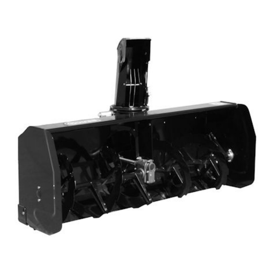
Page 22: 66'' Snowblower
PARTS BREAKDOWN 66’’ SNOWBLOWER... -
Page 23: Parts List
PARTS LIST 66’’ SNOWBLOWER Ref. Qty. Part # English description Description française Réf. Qté. Pièce # Frame 66" Châssis 66" 105583 Éventail 105475 Chute Goulotte 105476 Right skid shoe Patin droit 105486 Left skid shoe Patin gauche 105487 Retaining plate Plaque de retenue 105488 Hand guard... - Page 24 PARTS LIST 66’’ SNOWBLOWER Ref. Qty. Part # English description Description française Réf. Qté. Pièce # Rotation ring Anneau de rotation 105429 Shaft 66" Arbre 66" 105436 Flangette Flangette 102213 Electric motor Moteur électrique 103378 Rotation bushing Coussinet de rotation 103946 Oil lite bushing Coussinet imprégné...
- Page 25 PARTS LIST 66’’ SNOWBLOWER Ref. Qty. Part # English description Description française Réf. Qté. Pièce # Hex. bolt 3/8" n.c. x 1 1/4" Boulon hex. 3/8" n.c. x 1 1/4" Hex. bolt 3/8" n.c. x 1 3/4" Boulon hex. 3/8" n.c. x 1 3/4" Hex.
- Page 26 NOTES _____________________________________________________________________________________________ _____________________________________________________________________________________________ _____________________________________________________________________________________________ _____________________________________________________________________________________________ _____________________________________________________________________________________________ _____________________________________________________________________________________________ _____________________________________________________________________________________________ _____________________________________________________________________________________________ _____________________________________________________________________________________________ _____________________________________________________________________________________________ _____________________________________________________________________________________________ _____________________________________________________________________________________________ _____________________________________________________________________________________________ _____________________________________________________________________________________________ _____________________________________________________________________________________________ _____________________________________________________________________________________________ _____________________________________________________________________________________________ _____________________________________________________________________________________________ _____________________________________________________________________________________________ _____________________________________________________________________________________________ _____________________________________________________________________________________________ _____________________________________________________________________________________________ _____________________________________________________________________________________________ _____________________________________________________________________________________________...
-
Page 27: Options & Attachments
OPTIONS & ATTACHMENTS COUNTERWEIGHT TIRE CHAINS SNOW DRIFT CUTTER #700535 Model # as per tractor Two link spacing. Required for Facilitates and increases snow Required for safety and traction. traction and safety. intake. Counter-balances weight of Pkg. of 2 Pkg. of 2 attachment. - Page 28 WHEN PERFORMANCE & DEPENDABILITY ARE NON NEGOTIABLE ! Ber comac Limitée 92, For tin Nor th, Adstock, Quebec, Canada, G0N 1S0 WWW.BERCOMAC.COM PRINTED IN CANADA (ORIGINAL NOTICE)
Need help?
Do you have a question about the 700533-1 and is the answer not in the manual?
Questions and answers