Table of Contents
Advertisement
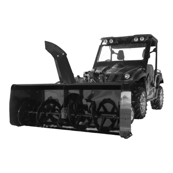
VANTAGE 66'' & 72'' Snowblower
READ & FOLLOW ALL SAFETY RULES & INSTRUCTIONS BEFORE
106275_EN
BERCO
OFF ROAD UTILITY VEHICLE
* ASSEMBLY
* OPERATION
CAUTION:
OPERATING YOUR EQUIPMENT
OWNER'S MANUAL
Model Number
700512-3-66'' Snowblower
700513-3-72'' Snowblower
For
* REPAIR PARTS
* MAINTENANCE
*106275*
1
Original Version
L-11
Advertisement
Table of Contents

Related Manuals for Bercomac 700512-3-66


Summary of Contents for Bercomac 700512-3-66
- Page 1 OWNER’S MANUAL Model Number Original Version 700512-3-66’’ Snowblower 700513-3-72’’ Snowblower BERCO VANTAGE 66’’ & 72’’ Snowblower OFF ROAD UTILITY VEHICLE * ASSEMBLY * REPAIR PARTS * OPERATION * MAINTENANCE CAUTION: READ & FOLLOW ALL SAFETY RULES & INSTRUCTIONS BEFORE OPERATING YOUR EQUIPMENT...
- Page 2 (manufacturer) replacement parts. have other rights, which vary from state to state. NOTE: Bercomac reserves the right to change or improve the design of any part or accessory without assuming any obligation to modify any product previously manufactured.
-
Page 3: Table Of Contents
TABLE OF CONTENTS INTRODUCTION ..............................SAFETY PRECAUTIONS ............................. SAFETY DECALS ..............................ASSEMBLY Tools Required ............................Snowblower Preparation ......................... Vehicle Preparation ..........................Preparing the Subframe .......................... Installing on the Vehicle .......................... Control Box Installation ........................... Installing the Spring ..........................OPERATION Burnishing Procedure ..........................Snowblower Operation .......................... -
Page 4: Introduction
INTRODUCTION TO THE PURCHASER This new accessory was carefully designed to give years of dependable service. This manual has been provided to assist in the safe operation and servicing of your attachment. NOTE: All photographs and illustrations in the manual may not necessarily depict the actual models or attachment, but are intended for reference only and are based on the latest product information available at the time of publication. -
Page 5: Safety Precautions
SAFETY PRECAUTIONS Careful operation is your best insurance against an accident. Read this section carefully before operating the vehicle and accessory. This accessory is capable of amputating hands and feet and throwing objects. Failure to observe the following safety instructions could result in serious injury. All operators, no matter how experienced they may be, should read this and other manuals related to the vehicle and accessory before operating. - Page 6 SAFETY PRECAUTIONS OPERATION: MAINTENANCE AND STORAGE Do not put hands or feet near, under or inside rotating parts. When cleaning, repairing or inspecting the vehicle and accessory, make certain that all moving parts Exercise extreme caution when operating on or have stopped.
-
Page 7: Safety Decals
SAFETY DECALS REPLACE IF DECALS ARE DAMAGED SEE PARTS BREAKDOWN FOR DECAL LOCATION Symbol Description Decal #105126 To avoid serious injury: Keep hands, feet & clothing away from rotating auger while engine is running. Decal #105127 To avoid serious injury: Keep hands out of this discharge chute while engine is running. -
Page 8: Assembly
ASSEMBLY CONVERSION TABLE GLOSSARY 1’’ (po, in) 25.4 mm Quad = V.T.T., A.T.V. 1’ (pi, ft) 0.3 m Véhicule tout terrain V.T.T. 1 psi (lb/in 6.89 kPa All terrain vehicle A.T.V. 1 lb 0.45 kg P.T.O. = P.D.F Power take-off (P.T.O) 1 lbf 4.4 N... -
Page 9: Snowblower Preparation
ASSEMBLY SNOWBLOWER PREPARATION: Refer parts breakdown section parts identification. Install the nylon rotation ring (item 1) over the opening (item 2) as shown and align the notches. Install the nylon rotation ring Install the rotation ring (item 1) over the opening as shown. -
Page 10: Vehicle Preparation
ASSEMBLY Insert the 1/4’’ x 1/2’’ hex bolts (item 1) in the holes as shown. Install the retaining plate (item 2) under the chute as shown. Secure in place with the 1/4’’ nylon insert lock nuts as shown. Install the retaining plate VEHICLE PREPARATION: Choose one of the three following options as a means of fastening the subframe. -
Page 11: Preparing The Subframe
ASSEMBLY PREPARING THE SUBFRAME Assemble the wheel support (item 1) on the subframe (item 2) with four hex bolts 3/8" x 1" (item 3) and four flange nuts 3/8" (item 4). NOTE: The set of holes used to assemble the wheel support to the subframe depends on the height of the vehicle. - Page 12 ASSEMBLY Among the three following configurations, choose the height of the hitch support. There must be a maximum of ground clearance. (Configuration A) does not have the hitch support plates (item 1). If applicable, assemble the hitch support plates on the hitch support (item 2) with four hex bolts 3/8"...
-
Page 13: Installing On The Vehicle
ASSEMBLY INSTALLING ON THE VEHICLE Place the hitch (item 1) on the tow hitch ball and secure in place with a pin (item 2) and a hair pin (item IMPORTANT Make sure the vehicle never comes into contact with the subframe even when the vehicle’s suspensions are compressed to the maximum. -
Page 14: Control Box Installation
ASSEMBLY CONTROL BOX INSTALLATION: Disconnect the wires that are connected to the control box (item 3). Install the box support (item 1) in an appropriate place . Drill holes if necessary. Secure the box support with the two 1/4’’ x 1/2’’ hex bolts and flange nuts. - Page 15 ASSEMBLY Connect the wire connector on the motor for the chute deflector (item 1) There will be one black connector that will not be connected. This connect optional snowblower light. Make sure the connectors are well connected together and tie the wire that is connected to the motor of the deflector (item 1) with a nylon tie wrap on the motor in such a way that the wire does not come into interference with the chute’s rotation.
-
Page 16: Installing The Spring
ASSEMBLY INSTALLING THE SPRING AND ADJUSTING THE LIFTING HEIGHT OF THE SNOWBLOWER. IMPORTANT: It is very important that the snowblower engine does not come into contact with the vehicle. If necessary, use on each side one or two shims (item 2) supplied with the kit to limit the lifting height. -
Page 17: Operation
OPERATION WARNING WARNING Never touch with your hands or feet the Read the vehicle's owner’s manual carefully. Be snowblower’s fan, auger or the chute because thoroughly familiar with the controls & proper this is the most frequent cause of accidents use of the attachment. -
Page 18: Snowblowing Technique
OPERATION SNOWBLOWING TECHNIQUE SKID SHOE ADJUSTMENT When removing snow, do not use the snowblower as a dozer blade to push snow. Allow snowblower to Level paved surface: Adjust skid shoes to allow 3/16” ingest snow at its own speed. If the speed of your to 1/4"... -
Page 19: Maintenance
MAINTENANCE WARNING WARNING Before doing any snowblower maintenance, -Do not attempt to clear plugged chute, auger or assembling or dismounting: fan of snow while the snowblower's engine is Apply parking brakes of the vehicle. running. Stop the snowblower engine and remove the -Disengage snowblower. -
Page 20: Lubrication
MAINTENANCE LUBRICATION SUBFRAME WHEELS Grease the wheel axles, the fork pivots after every sixteen hours of use. Apply oil at all pivot points. CHUTE ROTATION SYSTEM Oil the base of the chute every sixteen hours of operation. GEAR BOX : Check the oil annually. -
Page 21: Replacing The Augers, Fan And / Or Gear Box
MAINTENANCE REPLACING THE AUGERS, FAN AND / OR THE GEAR BOX For belt part numbers, refer to snowblower parts breakdown section for parts identification Snowblower must be detached & disconnected from the vehicle to replace the auger or the gear box. -
Page 22: Maintenance & Dismounting
DISMOUNTING & STORAGE DISMOUNTING STORAGE a) Select a level surface, set parking brake, stop the a) Clean snowblower and subframe thoroughly and engine, and remove the ignition key to prevent repaint all parts from which paint has worn. accidental starting. b) List the replacement parts that will be needed to b) Lower the accessory to the ground. -
Page 23: Troubleshooting
TROUBLESHOOTING * Please refer to parts breakdown section for parts identification. PROBLEM POSSIBLE CAUSES CORRECTIVE ACTION Snowblower vibrates or is Damaged pulley Replace pulley abnormally noisy or bouncing. Damaged bearing Replace the bearing Fan or the augers are damaged Remove and straighten or replace the parts Fan or auger bushings are worn Replace with new bushings... - Page 24 TROUBLESHOOTING * Please refer to parts breakdown section for parts identification. PROBLEM POSSIBLE CAUSES CORRECTIVE ACTION The engine does not start The emergency button is pushed The emergency button must be down. pulled up to start the engine of the snowblower.
-
Page 25: Torque Specification Table
TORQUE SPECIFICATION TABLE GENERAL TORQUE SPECIFICATION TABLE USE THE FOLLOWING TORQUES WHEN SPECIAL TORQUES ARE NOT GIVEN NOTE: These values apply to fasteners as received from supplier, dry or when lubricated with normal oil. They do not apply if special graphited or moly disulphide greases or other extreme pressure lubricants are used. This applies to both UNF and UNC threads. -
Page 26: Vantage Snowblower 66
PARTS BREAKDOWN VANTAGE SNOWBLOWER 66’’... - Page 27 PARTS LIST VANTAGE SNOWBLOWER 66’’ Ref. Qty. Part # English description Description française Réf. Qté. Pièce # Frame 66" Châssis 66" 106255 V pulley with set screw Poulie en V avec vis pression 105423 Gear box left rotation Boîte d'engrenage rotation gauche 105424 Auger 66"...
- Page 28 PARTS LIST VANTAGE SNOWBLOWER 66’’ Ref. Qty. Part # English description Description française Réf. Qté. Pièce # Reinforcement plate Plaque de renforcement 105730 Shim Cale 105731 Wire Assembly Extension Extension du fil assemblé 106118 Wire Assembly extension Extension du fil assemblé 106119 Control box assembly Boîte de contrôle assemblé...
- Page 29 PARTS LIST VANTAGE SNOWBLOWER 66’’ Ref. Qty. Part # English description Description française Réf. Qté. Pièce # Box support Support de la boîte 104756 Key 1/4" x 1/4" x 2.88" Clé 1/4" x 1/4" x 2.88" 104436 Key 1/4" x 1/4" x 2" Clé...
- Page 30 PARTS LIST VANTAGE SNOWBLOWER 66’’ Qty. Part # English description Description française Réf. Qté. Pièce # Carriage bolt 1/4" n.c. x 3/4 " GR5 Boulon à carrosserie 1/4" n.c. x 3/4" GR5 Carriage bolt 5/16" n.c. x 3/4 " GR5 Boulon à...
-
Page 31: Vantage Snowblower 72
PARTS BREAKDOWN VANTAGE SNOWBLOWER 72’’... - Page 32 PARTS LIST VANTAGE SNOWBLOWER 72’’ Ref. Qty. Part # English description Description française Réf. Qté. Pièce # Frame 72" Châssis 72" 106256 V pulley with set screw Poulie en V avec vis pression 105423 Gear box left rotation Boîte d'engrenage rotation gauche 105424 Auger 72"...
- Page 33 PARTS LIST VANTAGE SNOWBLOWER 72’’ Ref. Qty. Part # English description Description française Réf. Qté. Pièce # Reinforcement plate Plaque de renforcement 105730 Shim Cale 105731 Wire Assembly Extension Extension du fil assemblé 106118 Wire Assembly extension Extension du fil assemblé 106119 Control box assembly Boîte de contrôle assemblé...
- Page 34 PARTS LIST VANTAGE SNOWBLOWER 72’’ Ref. Qty. Part # English description Description française Réf. Qté. Pièce # Box support Support de la boîte 104756 Key 1/4" x 1/4" x 2.88" Clé 1/4" x 1/4" x 2.88" 104436 Key 1/4" x 1/4" x 2" Clé...
- Page 35 PARTS LIST VANTAGE SNOWBLOWER 72’’ Ref. Qty. Part # English description Description française Réf. Qté. Pièce # Carriage bolt 1/4" n.c. x 3/4 " GR5 Boulon à carrosserie 1/4" n.c. x 3/4" GR5 Carriage bolt 5/16" n.c. x 3/4 " GR5 Boulon à...
-
Page 36: Subframe
PARTS BREAKDOWN SUBFRAME... -
Page 37: Parts List
PARTS LIST SUBFRAME Ref. Qty. Part # English description Description française Réf. Qté. Pièce # Wheel support Support de roue 106000 Wheel Roue 105496 Tire 410/350-6 Pneu 410/350-6 105497 Inner tube 350-6 Chambre à air 350-6 105498 Goupille 105500 Rear bracket Fixation arrière 104956 Subframe... - Page 38 PARTS LIST SUBFRAME Ref. Qty. Part # English description Description française Réf. Qté. Pièce # Lift strap Sangle de relevage 103613 Hair pin 3mm Goupille à ressort 3mm 102617 Goupille 104961 Goupille 104999 Hair pin 4mm Goupille à ressort 4mm 102054 Wheel fork Fourche de roue...
-
Page 39: Honda Engine 24Hp
PARTS BREAKDOWN HONDA 24 HP ENGINE PARTS LIST HONDA 24 HP ENGINE Ref. Qty. Part # English description Description française Réf. Qté. Pièce # Honda engine 24 hp with key Moteur Honda 24 CV avec clé 105520 Honda muffler Silencieux Honda 105448 Shim Cale... -
Page 40: Kohler Engine 23Hp
PARTS BREAKDOWN KOHLER 23 HP ENGINE PARTS LIST KOHLER 23 HP ENGINE Ref. Qty. Part # English description Description française Réf. Qté. Pièce # Engine 23 HP (Kohler) Moteur 23 CV (Kohler) 104003 Wire assembly Fil assemblé 105218 Heat shield Pare-chaleur 104621 Shim... -
Page 41: Kohler Engine 27Hp
PARTS BREAKDOWN KOHLER 27 HP ENGINE PARTS LIST KOHLER 27 HP ENGINE Ref. Qty. Part # English description Description française Réf. Qté. Pièce # Engine CH-27 (Kohler) with key Moteur CH-27 (Kohler) avec clé 105521 Wire assembly Fil assemblé 105218 Heat shield Pare-chaleur 104621... -
Page 42: Options & Accessories
OPTIONS & ACCESSORIES #700535 #700456 #700516 SNOW DRIFT CUTTER LIGHT KIT 66’’ ROTARY BROOM Slices through high snow drifts to facilitate and Better visibility for night time use For UV increase snow intake. Package of 2. SUBFRAME EXTENSION #700524 SUPPORT FOR BATTERY #700485 (BATTERY NOT INCLUDED) For bigger vehicle... - Page 43 NOTES _____________________________________________________________________________________________ _____________________________________________________________________________________________ _____________________________________________________________________________________________ _____________________________________________________________________________________________ _____________________________________________________________________________________________ _____________________________________________________________________________________________ _____________________________________________________________________________________________ _____________________________________________________________________________________________ _____________________________________________________________________________________________ _____________________________________________________________________________________________ _____________________________________________________________________________________________ _____________________________________________________________________________________________ _____________________________________________________________________________________________ _____________________________________________________________________________________________ _____________________________________________________________________________________________ _____________________________________________________________________________________________ _____________________________________________________________________________________________ _____________________________________________________________________________________________ _____________________________________________________________________________________________ _____________________________________________________________________________________________ _____________________________________________________________________________________________ _____________________________________________________________________________________________ _____________________________________________________________________________________________ _____________________________________________________________________________________________...
- Page 44 WHEN PERFORMANCE & DEPENDABILITY ARE NON NEGOTIABLE ! Ber comac Limitée 92, For t in Nor t h, Adstock, Quebec, Canada, G0N 1S0 WWW.BERCOMAC.COM PRINTED IN CANADA (ORIGINAL NOTICE)
Need help?
Do you have a question about the 700512-3-66 and is the answer not in the manual?
Questions and answers