Table of Contents
Advertisement
Advertisement
Table of Contents

Related Manuals for Bercomac PRESTIGE 54


Summary of Contents for Bercomac PRESTIGE 54
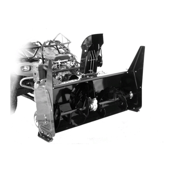
- Page 1 OWNER’S MANUAL Model Number 700360-6 Snowblower BERCO PRESTIGE 54’’ SNOWBLOWER ALL TERRAIN VEHICLES * ASSEMBLY * REPAIR PARTS * OPERATION * MAINTENANCE CAUTION: READ & FOLLOW ALL SAFETY RULES & INSTRUCTIONS BEFORE OPERATING YOUR EQUIPMENT *105192_EN* 105192_EN J-07...
- Page 2 NOTE: All warranty work must be performed by an authorized dealer using original (manufacturer) replacement parts. NOTE: Bercomac reserves the right to change or improve the design of any part or accessory without assuming any obligation to modify any product previously manufactured.
-
Page 3: Table Of Contents
TABLE OF CONTENTS PAGE INTRODUCTION ..............................SAFETY PRECAUTIONS ............................SAFETY DECALS ..............................ASSEMBLY Conversion Table, Glossary, Tools Required ................Step 1: Vehicle Preparation ........................Step 2: Subframe Preparation ......................... Installing the Winch Hook ......................Verify Skid Shoe Adjustment ...................... Step 3: Engine Preparation ........................Saddle Preparation ........................ -
Page 4: Introduction
INTRODUCTION TO THE PURCHASER This new accessory was carefully designed to give years of dependable service. This manual has been provided to assist in the safe operation and servicing of your attachment. NOTE: All photographs and illustrations in the manual may not necessarily depict the actual models or attachment, but are intended for reference only and are based on the latest product information available at the time of publication. -
Page 5: Safety Precautions
SAFETY PRECAUTIONS Careful operation is your best insurance against an accident. Read this section carefully before operating the vehicle and accessory. This accessory is capable of amputating hands and feet and throwing objects. Failure to observe the following safety instructions could result in serious injury. All operators, no matter how experienced they may be, should read this and other manuals related to the vehicle and accessory before operating. - Page 6 SAFETY PRECAUTIONS OPERATION: 13. Keep the accessory away from heat sources or flames. Do not put hands or feet near, under or inside rotating MAINTENANCE AND STORAGE parts. Exercise extreme caution when operating on or When cleaning, repairing or inspecting the vehicle crossing gravel drives, walks or roads.
-
Page 7: Safety Decals
SAFETY DECALS REPLACE IF DECALS ARE DAMAGED SEE PARTS BREAKDOWN FOR DECAL LOCATION DECAL #105126 DECAL #105130 To avoid serious injury: Keep hands, feet & clothing away from rotating auger while engine is running. Before installing or using: Locate, read and make sure to understand all of the DECAL #105127 owner’s manual. -
Page 8: Assembly
ASSEMBLY CONVERSION TABLE GLOSSARY 1’’ (po, in) 25.4 mm Quad = V.T.T., A.T.V. 1’ (pi, ft) 0.3 m Véhicule tout terrain V.T.T. 1 psi (lb/in 6.89 kPa All terrain vehicle A.T.V. 1 lb 0.45 kg P.T.O. = P.D.F 1 lbf 4.4 N Power take-off (P.T.O) -
Page 9: Step 1: Vehicle Preparation
ASSEMBLY STEP 1 VEHICLE PREPARATION: NOTE: A 1 7/8” or 50 mm tow hitch ball is required. Choose among the three different options to prepare your vehicle (A, B, C). A) Install the lift strap (item 1) by looping it around the suspension arm (as shown) on the vehicle. - Page 10 ASSEMBLY Install the assembled turnbuckles (item 1). # Item Description Action Assembled Install on subframe turnbuckle (qty 2) as shown Flat washer Install on the 3/8" (qty 2) assembled turnbuckles as shown Hex bolt Insert as shown 5/16" x 1"(qty 2) Nylon insert lock nut Install and tighten 5/16"...
- Page 11 ASSEMBLY Install the springs (item 2) on each side. # Item Description Action Hex nut 5/16" Insert on each eye (qty 2) bolt (item 3). Tighten about half way down. Spring (qty 2) Insert the spring into the spring link and hook the other end into the eye bolt.
- Page 12 ASSEMBLY You have seven different positions on the adjustment tube (item 1) (the the adjustment tube can be inverted) to adjust the length of the subframe. To choose the right adjustment, insert the adjustment tube (item 1) into the subframe (item 2) and insert the hitch support (item 3) on the adjustment tube.
-
Page 13: Installing The Winch Hook
ASSEMBLY Install the turnbuckles (item 1) into the brackets or into the lift straps. # Item Description Action Turnbuckle Adjust them so that the (qty 2) subframe is centered under the vehicle.* *Tighten the turnbuckles firmly in order to tighten the vehicle's suspension. -
Page 14: Step 3: Engine Preparation
ASSEMBLY STEP 3 ENGINE PREPARATION: CAUTION Oil must be added to this motor. Please refer motor’s owner’s manual instructions and proper winter oil recommendations. Connecting the wire assembly: The kit is equipped with a connector which will permit you to remove the snowblower quickly without having to remove the wiring. -
Page 15: Operation
OPERATION OPERATING THE SNOWBLOWER WARNING You must be sitting on the saddle in order to Read the A.T.V.’s owner’s manual carefully. Be start the snowblower engine. thoroughly familiar with the controls & proper use of the attachment. Know how to stop the unit a) Make sure the snowblower is clear of snow &... -
Page 16: Maintenance
OPERATION MAINTENANCE AUGER SHEAR BOLT WARNING REPLACEMENT TO PREVENT INJURIES: *Shear bolts are to be considered a preventive Stop the snowblower motor. measure and not an assured protection. Operator Apply parking brake. vigilance is required. Thoroughly inspect the areas Remove the ignition key. where the snowblower is to be used and remove all Disconnect the wire from the spark plug(s) and foreign objects. -
Page 17: Belt Replacement
OPERATION BELT REPLACEMENT BELT REPLACEMENT: For belt part numbers, refer to snowblower parts breakdown section for parts identification Snowblower must be detached & disconnected from the A.T.V. to replace belts. V-Belt: CAUTION a) Remove the belt guard (item 1) b) Remove the 7/16 x 5 1/2’’ hex bolt (item 2) from Never use the snowblower without the belt guard. - Page 18 MAINTENANCE BELT ADJUSTMENTS CAUTION Never use the snowblower without the belt guard. TIMING BELT ADJUSTMENT: (see following page for a good or improper pulley adjustment ) a) Remove the belt guard (item 1) to better see the belt alignment b) Unhook the spring (item 5) to facilitate the rotation of the fan.
-
Page 19: Belt Adjustments
************************* BELT ADJUSTMENTS CAUTION Never use the snowblower without the belt guard. IMPORTANT: The following figures (side views) show a good or improper adjustment of the pulleys in the reduction box (item 10). Improper adjustment: The pulleys are not well Good adjustment: The pulleys are well aligned and aligned and the timing belt does not stay completely the timing belt stays completely engaged on the... -
Page 20: Replacement Of One Or Two Sections Of The Auger And /Or Gear Box
REPLACEMENT OF ONE OR TWO SECTIONS OF THE AUGER AND / OR GEAR BOX For belt part numbers, refer to snowblower parts breakdown section for parts identification Snowblower must be detached & disconnected from the A.T.V. to replace the auger or the gear box. -
Page 21: Dismounting & Storage
DISMOUNTING & STORAGE DISMOUNTING THE SNOWBLOWER: STORAGE a) Select a level surface, set parking brake, stop the a) Clean snowblower and subframe thoroughly and engine, and remove the ignition key to prevent repaint all parts from which paint has worn. accidental starting. -
Page 22: Troubleshooting
TROUBLESHOOTING * Please refer to parts breakdown section for parts identification. PROBLEM POSSIBLE CAUSES CORRECTIVE ACTION Snowblower vibrates Damaged pulley. Replace pulley. abnormally noisy. Damaged bearing. Replace bearing. Damaged fan. Dismount & repair or replace fan. One or both sections of the auger is Replace one or both sections of bent. -
Page 23: Torque Specification Table
TORQUE SPECIFICATION TABLE GENERAL TORQUE SPECIFICATION TABLE USE THE FOLLOWING TORQUES WHEN SPECIAL TORQUES ARE NOT GIVEN NOTE: These values apply to fasteners as received from supplier, dry or when lubricated with normal oil. They do not apply if special graphited or moly disulphide greases or other extreme pressure lubricants are used. This applies to both UNF and UNC threads. -
Page 24: Rotation System With Chute
PARTS BREAKDOWN ROTATION SYSTEM WITH CHUTE... - Page 25 PARTS LIST ROTATION SYSTEM WITH CHUTE Ref. Qty. Part # English description Description française Réf. Qté. Pièce # Chute Goulotte 103936 Bracket Support 103971 Reinforcement plate Plaque de renforcement 103972 Spacer Espaceur 103368 Rotation ring Anneau de rotation 103974 Spacer Espaceur 103361 Bracket...
-
Page 26: Saddle Assembly
PARTS BREAKDOWN SADDLE ASSEMBLY... - Page 27 PARTS LIST SADDLE ASSEMBLY Ref. Qty. Part # English description Description française Réf. Qté. Pièce # Seat cover Couvre-siège 103987 Control board Tableau de contrôle 104011 Switch support Support de commutateur 104012 Safety switch ass'y Commutateur de sécurité ass'é 104014 Ignition switch Commutateur d'ignition 104015...
-
Page 28: Subframe
PARTS BREAKDOWN SUBFRAME... - Page 29 PARTS LIST SUBFRAME Ref. Qty. Part # English description Description française Réf. Qté. Pièce # Subframe Sous-châssis 104769 Wheel support Support de roue 104901 Adjustment tube Tube d'ajustement 104637 Caster wheel assembly Roue pivotante assemblée 104779 Inner tube 250-4 Chambre à air 250-4 102675 Tire 280/250-4 Pneu 280/250-4...
-
Page 30: Snowblower
PARTS BREAKDOWN SNOWBLOWER... - Page 31 PARTS LIST SNOWBLOWER Ref. Qty. Part # English description Description française Réf. Qté. Pièce # Frame 54" Châssis 54" 104896 Shaft 54" Arbre 54" 104722 Reduction plate Plaque de réduction 103959 Shaft Arbre 103961 Key 1/4" x 1/4" x 2 31/32 Clé...
- Page 32 PARTS LIST SNOWBLOWER Ref. Qty. Part # English description Description française Réf. Qté. Pièce # Oil lite bushing Coussinet imprégné d'huile 102784 Cutting edge 54" Racloir 54" 104427 Gear box support Support de boîte d'engrenage 104746 Left drift cutter Couteau à neige gauche 102821 Right drift cutter Couteau à...
- Page 33 PARTS LIST SNOWBLOWER Ref. Qty. Part # English description Description française Réf. Qté. Pièce # Nylon insert lock nut 7/16" n.c. Écrou à garniture de nylon 7/16" n.c. Nylon Insert lock Nut 1/2" n.c. Écrou à garniture de nylon 1/2" n.c. Hex.
-
Page 34: Options
OPTIONS EXTENSION AND SIDE WIDENING ANGLE KIT EXTENSION PANEL SUBFRAME EXTENSION #700461 . #700473 Widens the snowblower by 6’’ and Adds about 10’’ to the height of the #700475 adds about 7’’ to the height. snowblower For bigger vehicle... - Page 35 NOTES _____________________________________________________________________________________________ _____________________________________________________________________________________________ _____________________________________________________________________________________________ _____________________________________________________________________________________________ _____________________________________________________________________________________________ _____________________________________________________________________________________________ _____________________________________________________________________________________________ _____________________________________________________________________________________________ _____________________________________________________________________________________________ _____________________________________________________________________________________________ _____________________________________________________________________________________________ _____________________________________________________________________________________________ _____________________________________________________________________________________________ _____________________________________________________________________________________________ _____________________________________________________________________________________________ _____________________________________________________________________________________________ _____________________________________________________________________________________________ _____________________________________________________________________________________________ _____________________________________________________________________________________________ _____________________________________________________________________________________________ _____________________________________________________________________________________________ _____________________________________________________________________________________________ _____________________________________________________________________________________________ _____________________________________________________________________________________________...
- Page 36 WHEN PERFORMANCE & DEPENDABILITY ARE NON NEGOTIABLE ! Ber comac Limitée 92, For tin Nor th, Adstock, Quebec, Canada, G0N 1S0 WWW.BERCOMAC.COM PRINTED IN CANADA (ORIGINAL NOTICE)
Need help?
Do you have a question about the PRESTIGE 54 and is the answer not in the manual?
Questions and answers