Table of Contents
Advertisement
Quick Links
ALL TERRAIN VEHICLES & UTILITY VEHICLES
ALL TERRAIN VEHICLES & UTILITY VEHICLES
ALL TERRAIN VEHICLES & UTILITY VEHICLES
ALL TERRAIN VEHICLES & UTILITY VEHICLES
* ASSEMBLY
* OPERATION
READ & FOLLOW ALL SAFETY RULES & INSTRUCTIONS BEFORE
104773
BERCO PIONEER
BERCO PIONEER
BERCO PIONEER
BERCO PIONEER
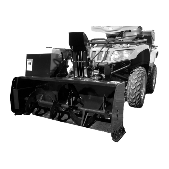
Two Stage 48" Snowblower
Two Stage 48" Snowblower
Two Stage 48" Snowblower
Two Stage 48" Snowblower
CAUTION:
CAUTION:
CAUTION:
CAUTION:
OPERATING YOUR EQUIPMENT
OWNER'S MANUAL
OWNER'S MANUAL
OWNER'S MANUAL
OWNER'S MANUAL
Model Number
Model Number
Model Number
Model Number
For
* REPAIR PARTS
* MAINTENANCE
1
700455
700455
700455
700455
H-09
Advertisement
Table of Contents

Related Manuals for Bercomac BERCO PIONEER 700455


Summary of Contents for Bercomac BERCO PIONEER 700455
- Page 1 OWNER’S MANUAL OWNER’S MANUAL OWNER’S MANUAL OWNER’S MANUAL Model Number Model Number Model Number Model Number 700455 700455 700455 700455 BERCO PIONEER BERCO PIONEER BERCO PIONEER BERCO PIONEER Two Stage 48" Snowblower Two Stage 48" Snowblower Two Stage 48" Snowblower Two Stage 48"...
- Page 2 NOTE: All warranty work must be performed by an authorized Note: BERCOMAC reserves the right to change or improve the design of any part or accessory without assuming any obligation to modify any product previously manufactured. Instructions for Obtaining Warranty Services: Contact dealer where equipment was purchased or any other Authorized Service Dealer to arrange service at their dealership.
-
Page 3: Table Of Contents
TABLE OF CONTENTS PAGE INTRODUCTION ..............................SAFETY PRECAUTIONS ............................SAFETY DECALS ..............................ASSEMBLY Step 1: Snowblower Preparation ......................Step 2: Engine Installation ........................Step 3: Vehicle Preparation ........................Step 4: Subframe Preparation ........................Step 5: Control Box Installation ........................ Step 6: Final Adjustments ......................... OPERATION Operating the Snowblower ........................ -
Page 4: Introduction
INTRODUCTION TO THE PURCHASER This new attachment was carefully designed to give years of dependable service. This manual has been provided to assist in the safe operation and servicing of your attachment. NOTE: All photographs and illustrations in the manual may not necessarily depict the actual models or attachment, but are intended for reference only and are based on the latest product information available at the time of publication. -
Page 5: Safety Precautions
SAFETY PRECAUTIONS Careful operation is your best insurance against an accident. Read this section carefully before operating the vehicle and accessory. This accessory is capable of amputating hands and feet and throwing objects. Failure to observe the following safety instructions could result in serious injury. All operators, no matter how experienced they may be, should read this and other manuals related to the vehicle and accessory before operating. - Page 6 SAFETY PRECAUTIONS 13.Never operate the accessory without good visibility OPERATION: or light. 1. Do not put hands or feet near, under or inside rotating parts. 14.Keep the accessory away from heat sources or flames. 2. Exercise extreme caution when operating on or crossing gravel drives, walks or roads.
-
Page 7: Safety Decals
SAFETY DECALS REPLACE IF DECALS ARE DAMAGED SEE PARTS BREAKDOWN FOR DECAL LOCATION Decal # 102125 Decal # 102126 Decal # 102128 Decal # 102127 Decal # 102553... -
Page 8: Assembly
ASSEMBLY IMPORTANT: TORQUE ALL BOLTS ACCORDING TO TORQUE SPECIFICATION TABLE (SEE TABLE CONTENTS) WHEN STATED: TIGHTEN FIRMLY. REFER PARTS BREAKDOWN SECTION FOR PART IDENTIFICATION. STEP 1 SNOWBLOWER PREPARATION: Overall view of snowblower Place the rotation ring (item 1) on top of the snow- blower (item 2) as shown. - Page 9 ASSEMBLY Grease the end of the rotation worm of the motor assembly (item 1). Insert the bushing (item 2) on the end of the rotation worm as shown. Insert the motor assembly in the sleeve (item 3). Insert bushings on rotation worm Install the motor assembly Apply grease on the rotation ring (item 1).
-
Page 10: Step 2: Engine Installation
ASSEMBLY STEP 2 ENGINE INSTALLATION: NOTE: THE RIGHT INSTALLATION OF THE ENGINE IS CRUCIAL TO THE GOOD WORKING ORDER OF THE SNOWBLOWER. NOTE: Figures 1 and 2 show an engine that is not well positioned. AXIS AXIS AXIS AXIS Figure 2 Figure 1 Engine not in right position Engine not in right position... - Page 11 ASSEMBLY INSTALLATION OTHER BRANDS ENGINES: Place the engine on a table. Measure the height (item B) from the middle of the crank shaft to the table. Use one of the two shims (3/4" or 1") if required, to attain the height of 5.25". If more or less height is needed, use a couple of flat washers.
-
Page 12: Step 3: Vehicle Preparation
ASSEMBLY Install the belts on the snowblower pulleys as shown. IMPORTANT: Make sure that each strand of the belts are inside the pins that are used as belt guides (item 4). NOTE: The adjustment with the tension on the belts will be done in Step 6. -
Page 13: Step 4: Subframe Preparation
ASSEMBLY STEP 4 SUBFRAME PREPARATION: Determine according to the height of the vehicle which set of holes to use to assemble the wheel support (item 1) to the subframe (item 2). The subframe must be parallel with the ground when the subframe is installed under the vehicle. - Page 14 ASSEMBLY You have nine different positions on the subframe extension (item 1) (the extension can be inverted) to adjust the length of the subframe. To choose the right adjustment, insert the subframe extension (item 1) into the subframe (item 2) and insert the hitch support (item 3) on the subframe extension.
- Page 15 ASSEMBLY Hook the turnbuckles (item 1) into the brackets (item 2) or into the lift straps (item 3) and adjust them so the subframe is centered under the vehicle. IMPORTANT: After adjusting the turnbuckles, tighten the nuts on the vehicle’s wheel supports firmly. Make sure to lock the nuts with the original locks.
-
Page 16: Step 5: Control Box Installation
ASSEMBLY STEP 5 CONTROL BOX INSTALLATION: Choose between the three different ways of securing the control box support (item 1). Insert the control box (item 2) in the support. Connect the connectors of the wire on the control box to the three corresponding electric motors (the motor for the chute, for the deflector and for the belt tensioner). - Page 17 ASSEMBLY IMPORTANT: Take the time to familiarize yourself with the location of the switches and with their use. NOTE: If the switches don’t match the right controls, reconnect the connectors with the right motors. Pay particular attention to the switch for the belt tensioner (item 4).
-
Page 18: Step 6: Final Adjustments
ASSEMBLY STEP 6 FINAL ADJUSTMENTS Adjust the idler pulley (item 2) as follows: After installing the belts, you may run the engine without the belt guard but only for the time needed to verify belt alignment. leave AXIS snowblower without supervision. Neither you or anyone must approach the moving parts. - Page 19 ASSEMBLY VERIFY SKID SHOE ADJUSTMENT: LEVEL PAVED SURFACE: Adjust skid shoes to allow 3/16" to 1/4" clearance (A) between cutting edge and surface. UNEVEN OR GRAVEL SURFACE: Adjust skid shoes to allow 1/2" to 5/8" clearance (A) between cutting edge and surface. Adjust skid shoes Install the engine protector (item 1) on the snowblower (item 2) as shown.
-
Page 20: Operation
OPERATION WARNING WARNING Read the vehicle's owner’s manual carefully. Be PREVENT INJURIES MORE thoroughly familiar with the controls & proper TRACTION WHEN USING SNOWBLOWER: use of the attachment. Know how to stop the unit -Do not drive faster than 3 km/hr (2 m/hr) with snowblower on the ground. -
Page 21: Maintenance & Dismounting
MAINTENANCE & DISMOUNTING SHEAR BOLT REPLACEMENT WARNING The shear bolt is to be considered a preventive measure and not an assured protection. Operator TO PREVENT INJURIES: vigilance is required. Thoroughly inspect the areas Stop the snowblower motor. where the snowblower is to be used and remove all foreign objects. -
Page 22: Belt Replacement
BELT REPLACEMENT CAUTION Never use the snowblower without the belt guard. BELT REPLACEMENT: For belt part numbers, refer to parts breakdown section for parts identification. a) Remove the belt guard. b) Remove the auger shear bolt. c) Remove the chain guard. d) Unlink the chain by removing the connecting link and take off the chain. -
Page 23: Troubleshooting
TROUBLESHOOTING (For identification, see the parts breakdown) PROBLEM POSSIBLE CAUSES CORRECTIVE ACTION Snowblower is noisy. New chain and new sprocket. Lubricate the roller chain. NOTE: Please note this NOTE: When snowblower is new it is snowblower may appear to be louder, the noise will decrease over noisy. - Page 24 TROUBLESHOOTING (For identification, see the parts breakdown) PROBLEM POSSIBLE CAUSES CORRECTIVE ACTION The chute plugs easily. Snowblower engine is turning too Always have engine at full R.P.M. slowly. when using the snowblower. Advancing too quickly with vehicle. Reduce speed. Allow snowblower to ingest snow at its own speed.
-
Page 25: Torque Specification Table
TORQUE SPECIFICATION TABLE GENERAL TORQUE SPECIFICATION TABLE USE THE FOLLOWING TORQUES WHEN SPECIAL TORQUES ARE NOT GIVEN NOTE: These values apply to fasteners as received from supplier, dry or when lubricated with normal oil. They do not apply if special graphited or moly disulphide greases or other extreme pressure lubricants are used. This applies to both UNF and UNC threads. -
Page 26: Rotation System With Chute
PARTS BREAKDOWN / NOMENCLATURE DES PIÈCES ROTATION SYSTEM WITH CHUTE SYSTÈME DE ROTATION AVEC GOULOTTE... - Page 27 PARTS LIST / LISTE DES PIÈCES Ref. English description Description française Qty. Part # Réf. Qté. Pièce # 1 Chute Goulotte 102058 2 Nylon flat washer 11/32" Rondelle plate de nylon 11/32" 102009 3 Nylon flat washer 7/16" Rondelle plate de nylon 7/16" 102011 4 Carriage bolt 5/16"...
-
Page 28: Subframe
PARTS BREAKDOWN / NOMENCLATURE DES PIÈCES SUBFRAME ASSEMBLY/ SOUS-CHÂSSIS ASSEMBLÉ... - Page 29 PARTS LIST / LISTE DES PIÈCES Ref. English description Description française Qty. Part # Réf. Qté. Pièce # 1 Subframe Sous-châssis 104769 2 Wheel support Support de roue 104770 3 Subframe extension Extension du sous-châssis 104637 4 Lock washer 3/8" Rondelle de blocage 3/8"...
-
Page 30: Snowblower
PARTS BREAKDOWN / NOMENCLATURE DES PIÈCES SNOWBLOWER / SOUFFLEUSE... - Page 31 PARTS LIST / LISTE DES PIÈCES Ref. English description Description française Qty. Part # Réf. Qté. Pièce # 1 Frame 48" Châssis 48" 104771 2 Hitch Attache 104768 3 Hex. bolt 3/8" n.c. x 4" Boulon hex. 3/8" n.c. x 4" 4 Gear box Boîte d'engrenage 102029...
- Page 32 PARTS LIST / LISTE DES PIÈCES Ref. English description Description française Qty. Part # Réf. Qté. Pièce # 31 Nylon insert lock nut 3/8" n.c. Écrou à garniture de nylon 3/8" n.c. 32 Hex. bolt 3/8" n.c. x 3/4" Boulon hex. 3/8" n.c. x 3/4" 33 Pulley 2.5ø...
- Page 33 PARTS LIST / LISTE DES PIÈCES Ref. Qty. Part # English description Description française Réf. Qté. Pièce # 62 Bracket Support 104754 63 Lever Levier 104755 64 Spacer Espaceur 103361 65 Oil lite bushing Coussinet imprégné d'huile 103362 66 Plate Plaque 103363 67 Hex.
-
Page 34: Options
OPTIONS #700269 #700301 #700261 LIFT CONNECTION KIT DRIFT EXTENSION KIT FOR 48" SNOW DRIFT CUTTER Reduces the effort required by the Increase snow intake. Slices through high snow drifts to facilitate and winch to lift the accessory. Prevents snow from getting in the engine. increase snow intake.
Need help?
Do you have a question about the BERCO PIONEER 700455 and is the answer not in the manual?
Questions and answers