
Related Manuals for Alcatel-Lucent OmniSwitch 6860N


Summary of Contents for Alcatel-Lucent OmniSwitch 6860N
- Page 1 Part No. 060390-10, Rev. R October 2022 OmniSwitch 6860/6860E/6860N Hardware Users Guide www.al-enterprise.com...
- Page 2 The specifications described in this guide are subject to change without notice. The Alcatel-Lucent name and logo are trademarks of Nokia used under license by ALE. To view other trademarks used by affiliated companies of ALE Holding, visit: www.al-enterprise.com/en/legal/trade- marks-copyright.
-
Page 3: Table Of Contents
Contents About This Guide ......................ix Supported Platforms ......................ix Who Should Read this Manual? ..................ix When Should I Read this Manual? ..................ix What is in this Manual? ...................... x What is Not in this Manual? ....................x How is the Information Organized? ................... - Page 4 Contents Logging In to the Switch ..................2-7 Setting IP Address Information for the EMP ............2-8 Unlocking Session Types ..................2-9 Changing the Login Password ..................2-9 Setting the System Time Zone ................2-10 Setting the Date and Time ..................2-10 Setting Optional Parameters ...................2-10 Specifying an Administrative Contact .............
- Page 5 OmniSwitch 6860N-P24M ..................3-30 OS6860N-P24M Front Panel ................3-30 OS6860N-P24M Rear Panel ................3-30 OS6860N-P24M Chassis Specifications ............3-31 OmniSwitch 6860N Uplink Modules ..............3-32 OS68-XNI-U4 Front Panel ................3-32 OS68-QNI-U2 Front Panel ................3-32 OS68-VNI-U4 Front Panel ................3-33 OS68-CNI-U1 Front Panel ................3-33 Chassis Status LEDs ....................3-34...
- Page 6 Contents OS6860-BP-PH LED States ................3-48 OS6860N-BPPH 600W Power Supply ..............3-49 LED States ....................... 3-49 OS6860-BP-PX 920W Power Supply ..............3-50 OS6860-BP-PX LED States ................3-50 OS6860N-BPPX 920W Power Supply ..............3-51 LED States ....................... 3-51 OS6860N-BPXL 2000W Power Supply ..............3-52 LED States ....................... 3-52 DC Power Supply Connections ................
- Page 7 Contents Priority Disconnect is Disabled ............... 4-12 Understanding Guard Band ................... 4-12 Monitoring Power over Ethernet via CLI ..............4-13 ..........A-1 Appendix A Regulatory Compliance and Safety Information Declaration of Conformity: CE Mark ................A-1 Waste Electrical and Electronic Equipment (WEEE) Statement ......A-1 China RoHS: Hazardous Substance Table ............
- Page 8 Contents viii OmniSwitch 6860 Hardware Users Guide October 2022...
-
Page 9: About This Guide
About This Guide This OmniSwitch 6860 Hardware Users Guide describes OmniSwitch 6860 switch components and basic switch hardware procedures. Supported Platforms The information in this guide applies only to OmniSwitch 6860 switches. Who Should Read this Manual? The audience for this users guide is network administrators and IT support personnel who need to configure, maintain, and monitor switches and routers in a live network. -
Page 10: What Is In This Manual
What is in this Manual? This users guide includes the following hardware-related information: • Descriptions of “Availability” features. • Technical specifications for the chassis, power supplies and modules. • Power supply requirements. • The dynamics of chassis airflow, including detailed illustrations of proper and improper airflow configurations. -
Page 11: Documentation Roadmap
Documentation Roadmap The OmniSwitch user documentation suite was designed to supply you with information at several critical junctures of the configuration process.The following section outlines a roadmap of the manuals that will help you at each stage of the configuration process. Under each stage, we point you to the manual or manuals that will be most helpful to you. - Page 12 Anytime The OmniSwitch CLI Reference Guide contains comprehensive information on all CLI commands supported by the switch. This guide includes syntax, default, usage, example, related CLI command, and CLI-to-MIB variable mapping information for all CLI commands supported by the switch. This guide can be consulted anytime during the configuration process to find detailed and specific information on each CLI command.
-
Page 13: Related Documentation
• OmniSwitch Transceivers Guide Includes SFP and XFP transceiver specifications and product compatibility information. • Technical Tips, Field Notices Includes information published by Alcatel-Lucent’s Customer Support group. • Release Notes Includes critical Open Problem Reports, feature exceptions, and other important information on the features supported in the current release and any limitations to their support. -
Page 14: Technical Support
With 24-hour access to Alcatel-Lucent’s Service and Support web page, you’ll be able to view and update any case (open or closed) that you have reported to Alcatel-Lucent’s technical support, open a new case or access helpful release notes, technical bulletins, and manuals. -
Page 15: Chapter 1 Omniswitch 6860
1 OmniSwitch 6860 Refer to the information below for OmniSwitch 6860 (OS6860) models and components. Model Number Description OS6860-24 Fixed-configuration chassis in a 1U form factor with 24 10/100/1000 Base-T ports, four fixed SFP+ (1G/10G) ports and two 20G Virtual Chassis link ports. OS6860-P24 Fixed-configuration chassis in a 1U form factor with 24 10/100/1000 Base-T PoE ports, four fixed SFP+ (1G/10G) ports and two 20G Virtual Chassis... - Page 16 150W power supply.) All models include one console connector (for use with Micro USB-to-USB cable, included); one USB connector (for use with Alcatel-Lucent flash drive or Bluetooth dongle, not included); and one RS-232 connector.
-
Page 17: Omniswitch 6860 Availability Features
OmniSwitch 6860 OmniSwitch 6860 Availability Features OmniSwitch 6860 Availability Features The switch provides a broad variety of availability features. Availability features are hardware and software-based safeguards that help prevent the loss of data flow in the unlikely event of a subsystem failure. -
Page 18: Hardware Monitoring
OmniSwitch 6860 Availability Features OmniSwitch 6860 Hardware Monitoring Automatic Monitoring Automatic monitoring refers to the switch’s built-in sensors that automatically monitor operations. If an error is detected (e.g., over-threshold temperature), the switch immediately sends a trap to the user. The trap is displayed on the console in the form of a text error message. -
Page 19: Chapter 2 Getting Started
Electrical Requirements Note. Alcatel-Lucent switches must be installed by a professional installer. It is the responsibility of the installer to ensure that proper grounding is available and that the installation meets applicable local and national electrical codes. -
Page 20: Electrical Surge Warning
Installing the Hardware Getting Started Redundant AC Power. It is recommended that each AC outlet resides on a separate circuit. With redundant AC, if a single circuit fails, the switch’s remaining power supplies (on separate circuits) can remain operational. For switches using DC power, refer to the “DC Power Supply Connections”... -
Page 21: Unpacking And Installing The Switch
Getting Started Installing the Hardware Unpacking and Installing the Switch To protect your switch components from damage, read all unpacking recommendations and instructions carefully before beginning. Unpack your OmniSwitch 6860 chassis as close as possible to the location where it will be installed. Items Included Your OmniSwitch 6860 includes the following items: OmniSwitch chassis with power supplies, per order... -
Page 22: Airflow Considerations
Mounting the Switch Getting Started Airflow Considerations To ensure proper airflow, be sure that the switch is placed in a clean, well-ventilated area free of dust and debris and provide minimum recommended clearance at the front, back and sides of the switch. Never obstruct chassis air vents. -
Page 23: Connections And Cabling
Getting Started Connections and Cabling Connections and Cabling Once your switch is properly installed, you should connect all network and management cables required for your network applications. Connections may include: Micro USB-to-USB cable to the console connector • Ethernet cable to the Ethernet Management Port (EMP) (‘E’ and ‘N’ models only) •... -
Page 24: Booting The Switch
If the LEDs do not display as indicated, make sure the boot process is complete. If the LEDs do not display as indicated following a complete boot sequence, contact Alcatel-Lucent Customer Support. For complete information on LED states, refer to “Chassis Status LEDs”... -
Page 25: Your First Login Session
CLI command prompt: Welcome to the Alcatel-Lucent OS6860E-P48 8.1.1, April 15, 2014. Copyright (c) 1994-2014 Alcatel-Lucent. All Rights Reserved. OmniSwitch(tm) is a trademark of Alcatel-Lucent, registered in the United States Patent and Trademark Office. ->... -
Page 26: Setting Ip Address Information For The Emp
Your First Login Session Getting Started Setting IP Address Information for the EMP If installing an Enhanced OS6860 model (OS6860E), the IP address may be set via the Ethernet Management Port (EMP). To connect to the switch through the EMP Ethernet connection, use the default address below or change the port’s IP address. -
Page 27: Unlocking Session Types
Getting Started Your First Login Session Unlocking Session Types Security is a key feature on OmniSwitch 6860 switches. As described on page 2-7, when you access the switch for the first time, you must use a direct console port connection. All other session types (Telnet, FTP, WebView, and SNMP) are locked out until they are manually unlocked by the user. -
Page 28: Setting The System Time Zone
Your First Login Session Getting Started New password settings are automatically saved in real time to the local user database; the user is not required to enter an additional command in order to save the password information. Also note that new password information is retained following a reboot. -
Page 29: Viewing Your Changes
Getting Started Your First Login Session Viewing Your Changes To view your current changes, enter show system at the CLI prompt. Saving Your Changes Once you have configured this basic switch information, save your changes by entering write memory at the CLI command prompt. - Page 30 Your First Login Session Getting Started page 2-12 OmniSwitch 6860 Hardware Users Guide October 2022...
- Page 31 3 Chassis and Power Supplies This chapter includes detailed information on the OmniSwitch 6860 switch. Topics include: Chassis details and technical specifications: • Basic Models - Non-PoE OS6860-24, page 3-3. OS6860-48, page 3-5. Basic Models - PoE OS6860-P24, page 3-7. OS6860-P48, page 3-9.
- Page 32 Chassis and Power Supplies Temperature management, page 3-62. • Monitoring the chassis components via the Command Line Interface (CLI), page 3-62 • page 3-2 OmniSwitch 6860 Hardware Users Guide October 2022...
-
Page 33: Omniswitch 6860 Chassis Details
Chassis and Power Supplies OmniSwitch 6860 Chassis Details OmniSwitch 6860 Chassis Details OmniSwitch 6860-24 OS6860-24 Front Panel PS BPS GRN PS BPS GRN OS6860-24 OS6860-24 RS232 RS232 Item Description Virtual Chassis ID LED Status LEDs USB port Console port RS-232 port (24) 10/100/1000 Base-T ports (4) fixed SFP+ (1G/10G) ports (2) 20G Virtual Chassis link ports... -
Page 34: Os6860-24 Chassis Specifications
OmniSwitch 6860 Chassis Details Chassis and Power Supplies OS6860-24 Chassis Specifications Chassis Height 4.4 cm (1.73 in) Chassis Width 44 cm (17.33 in) Chassis Depth 35 cm (13.78 in) OS6860-24 Chassis Weight 4.45 kg (9.8 lb) OS6860-24 Chassis Weight (fully populated) 5.17 kg (11.4 lb) OS6860-24 Power Consumption (full system power) 46 W... -
Page 35: Omniswitch 6860-48
Chassis and Power Supplies OmniSwitch 6860 Chassis Details OmniSwitch 6860-48 OS6860-48 Front Panel PS BPS GRN PS BPS GRN OS6860-48 OS6860-48 RS232 RS232 Item Description Virtual Chassis ID LED Status LEDs USB port Console port RS-232 port (48) 10/100/1000 Base-T ports (4) fixed SFP+ (1G/10G) ports (2) 20G Virtual Chassis link ports CLASS 1 M LASER CAUTION. -
Page 36: Os6860-48 Chassis Specifications
OmniSwitch 6860 Chassis Details Chassis and Power Supplies OS6860-48 Chassis Specifications Chassis Height 4.4 cm (1.73 in) Chassis Width 44 cm (17.33 in) Chassis Depth 35 cm (13.78 in) OS6860-48 Chassis Weight 4.67 kg (10.3 lb) OS6860-48 Chassis Weight (fully populated) 5.40 kg (11.9 lb) OS6860-48 Power Consumption (full system power) 57 W... -
Page 37: Omniswitch 6860-P24
Chassis and Power Supplies OmniSwitch 6860 Chassis Details OmniSwitch 6860-P24 OS6860-P24 Front Panel PS BPS GRN PS BPS GRN OS6860-P24 OS6860-P24 RS232 RS232 Item Description Virtual Chassis ID LED Status LEDs USB port Console port RS-232 port (24) 10/100/1000 Base-T 802.3at PoE ports (4) fixed SFP+ (1G/10G) ports (2) 20G Virtual Chassis link ports CLASS 1 M LASER CAUTION. -
Page 38: Os6860-P24 Chassis Specifications
OmniSwitch 6860 Chassis Details Chassis and Power Supplies OS6860-P24 Chassis Specifications Chassis Height 4.4 cm (1.73 in) Chassis Width 44 cm (17.33 in) Chassis Depth 35 cm (13.78 in) OS6860-P24 Chassis Weight 4.58 kg (10.1 lb) OS6860-P24 Chassis Weight (fully populated) 6.03 kg (13.3 lb) OS6860-P24 Power Consumption (full system power) 75 W... -
Page 39: Omniswitch 6860-P48
Chassis and Power Supplies OmniSwitch 6860 Chassis Details OmniSwitch 6860-P48 OS6860-P48 Front Panel PS BPS GRN PS BPS GRN OS6860-P48 OS6860-P48 RS232 RS232 Item Description Virtual Chassis ID LED Status LEDs USB port Console port RS-232 port (48) 10/100/1000 Base-T 802.3at PoE ports (4) fixed SFP+ (1G/10G) ports (2) 20G Virtual Chassis link ports CLASS 1 M LASER CAUTION. -
Page 40: Os6860-P48 Chassis Specifications
OmniSwitch 6860 Chassis Details Chassis and Power Supplies OS6860-P48 Chassis Specifications Chassis Height 4.4 cm (1.73 in) Chassis Width 44 cm (17.33 in) Chassis Depth 35 cm (13.78 in) OS6860-P48 Chassis Weight 4.90 kg (10.8 lb) OS6860-P48 Chassis Weight (fully populated) 6.35 kg (14.0 lb) OS6860-P48 Power Consumption (full system power) 89 W... -
Page 41: Omniswitch 6860E-24
Chassis and Power Supplies OmniSwitch 6860 Chassis Details OmniSwitch 6860E-24 OS6860E-24 Front Panel PS BPS OS6860E-24 RS232 Item Description Virtual Chassis ID LED Status LEDs USB port Console port RS-232 port (24) 10/100/1000 Base-T ports (4) fixed SFP+ (1G/10G) ports (2) 20G Virtual Chassis link ports CLASS 1 M LASER CAUTION. -
Page 42: Os6860E-24 Chassis Specifications
OmniSwitch 6860 Chassis Details Chassis and Power Supplies OS6860E-24 Chassis Specifications Chassis Height 4.4 cm (1.73 in) Chassis Width 44 cm (17.33 in) Chassis Depth 35 cm (13.78 in) OS6860E-24 Chassis Weight 4.58 kg (10.1 lb) OS6860E-24 Chassis Weight (fully populated) 5.26 kg (11.6 lb) OS6860E-24 Power Consumption (full system power) 48 W... -
Page 43: Omniswitch 6860E-48
Chassis and Power Supplies OmniSwitch 6860 Chassis Details OmniSwitch 6860E-48 OS6860E-48 Front Panel PS BPS OS6860E-48 RS232 Item Description Virtual Chassis ID LED Status LEDs USB port Console port RS-232 port (48) 10/100/1000 Base-T ports (4) fixed SFP+ (1G/10G) ports (2) 20G Virtual Chassis link ports CLASS 1 M LASER CAUTION. -
Page 44: Os6860E-48 Chassis Specifications
OmniSwitch 6860 Chassis Details Chassis and Power Supplies OS6860E-48 Chassis Specifications Chassis Height 4.4 cm (1.73 in) Chassis Width 44 cm (17.33 in) Chassis Depth 35 cm (13.78 in) OS6860E-48 Chassis Weight 4.81 kg (10.6 lb) OS6860E-48 Chassis Weight (fully populated) 5.49 kg (12.1 lb) OS6860E-48 Power Consumption (full system power) 60 W... -
Page 45: Omniswitch 6860E-U28
Chassis and Power Supplies OmniSwitch 6860 Chassis Details OmniSwitch 6860E-U28 OS6860E-U28 Front Panel Item Description Virtual Chassis ID LED Status LEDs USB port Console port RS-232 port (28) 1000Base-X/100Base-FX ports (4) fixed SFP+ (1G/10G) ports (2) 20G Virtual Chassis link ports CLASS 1 M LASER CAUTION. -
Page 46: Os6860E-U28 Chassis Specifications
OmniSwitch 6860 Chassis Details Chassis and Power Supplies OS6860E-U28 Chassis Specifications Chassis Height 4.4 cm (1.73 in) Chassis Width 44 cm (17.33 in) Chassis Depth 35 cm (13.78 in) OS6860E-U28 Chassis Weight 4.58 kg (10.1 lb) OS6860E-U28 Chassis Weight (fully populated) 5.26 kg (11.6 lb) OS6860E-U28 Power Consumption (full system power) 73 W... -
Page 47: Omniswitch 6860E-P24
Chassis and Power Supplies OmniSwitch 6860 Chassis Details OmniSwitch 6860E-P24 OS6860E-P24 Front Panel PS BPS OS6860E-P24 RS232 Item Description Virtual Chassis ID LED Status LEDs USB port Console port RS-232 port (4) 10/100/1000 Base-T HPoE (60W - not 802.3bt compliant) ports (20) 10/100/1000 Base-T 802.3at PoE ports (4) fixed SFP+ (1G/10G) ports (2) 20G Virtual Chassis link ports... -
Page 48: Os6860E-P24 Chassis Specifications
OmniSwitch 6860 Chassis Details Chassis and Power Supplies OS6860E-P24 Chassis Specifications Chassis Height 4.4 cm (1.73 in) Chassis Width 44 cm (17.33 in) Chassis Depth 35 cm (13.78 in) OS6860E-P24 Chassis Weight 4.81 kg (10.6 lb) OS6860E-P24 Chassis Weight (fully populated) 6.26 kg (13.8 lb) OS6860E-P24 Power Consumption (full system power) 76 W... -
Page 49: Omniswitch 6860E-P48
Chassis and Power Supplies OmniSwitch 6860 Chassis Details OmniSwitch 6860E-P48 OS6860E-P48 Front Panel PS BPS OS6860E-P48 RS232 Item Description Virtual Chassis ID LED Status LEDs USB port Console port RS-232 port (4) 10/100/1000 Base-T HPoE (60W - not 802.3bt compliant) ports (44) 10/100/1000 Base-T 802.3at PoE ports (4) fixed SFP+ (1G/10G) ports (2) 20G Virtual Chassis link ports... -
Page 50: Os6860E-P48 Chassis Specifications
OmniSwitch 6860 Chassis Details Chassis and Power Supplies OS6860E-P48 Chassis Specifications Chassis Height 4.4 cm (1.73 in) Chassis Width 44 cm (17.33 in) Chassis Depth 35 cm (13.78 in) OS6860E-P48 Chassis Weight 5.03 kg (11.1 lb) OS6860E-P48 Chassis Weight (fully populated) 6.49 kg (14.3 lb) OS6860E-P48 Power Consumption (full system power) 93 W... -
Page 51: Omniswitch 6860E-P24Z8
Chassis and Power Supplies OmniSwitch 6860 Chassis Details OmniSwitch 6860E-P24Z8 OS6860E-P24Z8 Front Panel Item Description Virtual Chassis ID LED Status LEDs USB port Console port RS-232 port (16) 10/100/1000 Base-T 802.3at PoE ports (8) 100/1000/2.5G Base-T(75W HPoE Ports - not 802.3bt compliant) (4) fixed SFP+ (1G/10G) ports (2) 20G Virtual Chassis link ports CLASS 1 M LASER CAUTION... -
Page 52: Os6860E-P24Z8 Chassis Specifications
OmniSwitch 6860 Chassis Details Chassis and Power Supplies OS6860E-P24Z8 Chassis Specifications Chassis Height 4.4 cm (1.73 in) Chassis Width 44 cm (17.33 in) Chassis Depth 35 cm (13.78 in) Chassis Weight 4.81 kg (10.6 lb) Chassis Weight (fully populated) 6.26 kg (13.8 lb) Power Consumption (full system power) Altitude 13,000 ft... -
Page 53: Omniswitch 6860N-U28
Chassis and Power Supplies OmniSwitch 6860 Chassis Details OmniSwitch 6860N-U28 OS6860N-U28 Front Panel Item Description Virtual Chassis ID LED Status LEDs USB port EMP port Console port (24) SFP (100M/1G) - Ports 1-24 (4) SFP+ (1G/10G) - Ports 25-28 (2) QSFP28 (VFL) - Ports 29-30 (4) SFP28 (1G/10G/25G) - Ports 31-34 Note: The OS6860N-U28 doesn’t support a mix of 1G/10G and 25G speeds on the 4-port group of... -
Page 54: Os6860N-U28 Chassis Specifications
OmniSwitch 6860 Chassis Details Chassis and Power Supplies OS6860N-U28 Chassis Specifications Chassis Height 4.4 cm (1.73 in) Chassis Width 44 cm (17.33 in) Chassis Depth 35 cm (13.78 in) Chassis Weight 5.60 kg (12.36 lb) Power Consumption (full system power) 143W Altitude 13,000 ft... -
Page 55: Omniswitch 6860N-P48Z
Chassis and Power Supplies OmniSwitch 6860 Chassis Details OmniSwitch 6860N-P48Z OS6860N-P48Z Front Panel Item Description Virtual Chassis ID LED Status LEDs USB port EMP port Console port (36) 10/100/1000 Base-T 802.3bt PoE (60W) - Ports 1-36 (12) 100M/1G/2.5G/5G Base-T 802.3bt PoE (95W) - Ports 37-48... -
Page 56: Os6860N-P48Z Chassis Specifications
OmniSwitch 6860 Chassis Details Chassis and Power Supplies OS6860N-P48Z Chassis Specifications Chassis Height 4.4 cm (1.73 in) Chassis Width 44 cm (17.32 in) Chassis Depth 44 cm (17.32 in) Chassis Weight 7.80 kg (17.2 lb) Power Consumption (full system power) 147W Altitude 13,000 ft... -
Page 57: Omniswitch 6860N-P48M
Chassis and Power Supplies OmniSwitch 6860 Chassis Details OmniSwitch 6860N-P48M OS6860N-P48M Front Panel Item Description Status LEDs (36) 100M/1G/2.5G Base-T 802.3bt PoE (95W) - Ports 1-36 (12) 100M/1G/2.5G/5G/10G Base-T 802.3bt PoE (95W) - Ports 37-48 (2) QSFP28 (VFL) - Ports 49-50... -
Page 58: Os6860N-P48M Chassis Specifications
OmniSwitch 6860 Chassis Details Chassis and Power Supplies OS6860N-P48M Chassis Specifications Chassis Height 4.4 cm (1.73 in) Chassis Width 44 cm (17.32 in) Chassis Depth 44 cm (17.32 in) Chassis Weight 8.50 kg (18.76 lb) Power Consumption (full system power) 260W Altitude 13,000 ft... -
Page 59: Omniswitch 6860N-P24Z
Chassis and Power Supplies OmniSwitch 6860 Chassis Details OmniSwitch 6860N-P24Z OS6860N-P24Z Front Panel Item Description Virtual Chassis ID LED Status LEDs USB port EMP port Console port (12) 10/100/1000 Base-T 802.3bt PoE (60W) ports (12) 100M/1G/2.5G/5G Base-T 802.3bt PoE (95W) ports... -
Page 60: Os6860N-P24Z Chassis Specifications
OmniSwitch 6860 Chassis Details Chassis and Power Supplies Item Description Power Supply Bays OS6860N-P24Z Chassis Specifications Chassis Height 4.4 cm (1.73 in) Chassis Width 44 cm (17.32 in) Chassis Depth 44 cm (17.32 in) Chassis Weight 7.76 kg (17.11 lb) Power Consumption (full system power) 142 W Altitude... -
Page 61: Omniswitch 6860N-P24M
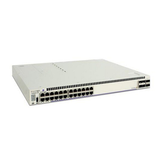
Chassis and Power Supplies OmniSwitch 6860 Chassis Details OmniSwitch 6860N-P24M OS6860N-P24M Front Panel Item Description Virtual Chassis ID LED Status LEDs USB port EMP port Console port (24) 100M/1G/2.5G/5G/10G Base-T 802.3bt PoE (95W) ports (2) QSFP28 VFL ports Uplink Module (Slot 2) CLASS 1 M LASER CAUTION CAUTION - CLASS 1 M LASER RADIATION WHEN OPEN. -
Page 62: Os6860N-P24M Chassis Specifications
OmniSwitch 6860 Chassis Details Chassis and Power Supplies OS6860N-P24M Chassis Specifications Chassis Height 4.4 cm (1.73 in) Chassis Width 44 cm (17.32 in) Chassis Depth 44 cm (17.32 in) Chassis Weight 8.38 kg (18.47 lb) Power Consumption (full system power) 176 W Altitude 13,000 ft... -
Page 63: Omniswitch 6860N Uplink Modules
Chassis and Power Supplies OmniSwitch 6860 Chassis Details OmniSwitch 6860N Uplink Modules OS68-XNI-U4 Front Panel Item Description Status LEDs (4) SFP+ (1G/10G) ports OS68-QNI-U2 Front Panel Item Description Status LEDs (2) QSFP+ (40G) ports OmniSwitch 6860 Hardware Users Guide October 2022... -
Page 64: Os68-Vni-U4 Front Panel
OmniSwitch 6860 Chassis Details Chassis and Power Supplies OS68-VNI-U4 Front Panel Item Description Status LEDs (4) SFP28 (1G/10G/25G) ports Note: The OS68-VNI-U4 doesn’t support a mix of 1G/10G and 25G speeds. Ports must all run at either 1G/10G speed or 25G speed. Mixing 1G and 10G speeds is supported. OS68-CNI-U1 Front Panel Item Description... -
Page 65: Chassis Status Leds
Chassis and Power Supplies OmniSwitch 6860 Chassis Details Chassis Status LEDs The chassis provides a series of status LEDs located on the front panel. These LEDs offer basic status information for hardware operation and port link and activity status. State Description Solid Green System Diagnostics and AOS bootup OK... - Page 66 OmniSwitch 6860 Chassis Details Chassis and Power Supplies State Description OK2 (Enhanced Solid Green External CPU Diagnostics and AOS models only) bootup OK Blinking Green External CPU Diagnostics in progress External CPU Diagnostic and/or AOS Solid Amber bootup failed Port LEDs Solid Green Valid port link (non-PoE) Blinking Green...
-
Page 67: Mounting The Switch
Chassis and Power Supplies Mounting the Switch Mounting the Switch General Mounting Recommendations Elevated Operating Ambient Temperature. If installed in a closed or multi-rack assembly, the operating ambient temperature of the rack environment may be greater than the room’s ambient temperature. -
Page 68: Airflow Recommendations
Mounting the Switch Chassis and Power Supplies Airflow Recommendations To ensure proper airflow, be sure that your switch is placed in a well-ventilated area and provide minimum recommended clearance at the front, back and sides of the switch, as shown below. Restricted airflow can cause your switch to overheat, which can lead to switch failure. -
Page 69: Blank Cover Panels
Chassis and Power Supplies Mounting the Switch Blank Cover Panels Blank cover panels are provided with your switch and are used to cover empty slots. These cover panels play an important role in chassis airflow and temperature management. If your switch is not fully populated and blank cover panels are not installed over empty slot locations, airflow is adversely affected. -
Page 70: Rack-Mounting
The chassis has rack-mount flanges that support standard 19-inch rack mount installations. • Alcatel-Lucent Enterprise does not provide rack-mount screws. Use the screws supplied by the • rack vendor. - Page 71 Chassis and Power Supplies Rack-Mounting Press the flange and spring clip until the flange clicks into place and the clip is in the in (engaged) position. Clip in “In” (engaged) position “CLICK” Secure the flange to the chassis using the attachment screw (provided). Repeat steps 1 through 4 for the flange on the opposite side of the chassis.
-
Page 72: Installing The Chassis In The Rack
Rack-Mounting Chassis and Power Supplies Installing the Chassis In the Rack Mark the holes on the rack where the chassis is to be installed. One person should lift and position the chassis until the rack-mount flanges are flush with the rack post. -
Page 73: Standalone (Non-Rack Mounted) Installations
Chassis and Power Supplies Rack-Mounting Standalone (Non-Rack Mounted) Installations The chassis can also be placed unmounted on a stable, flat surface as a standalone unit. Be sure that the surface can accommodate the full, populated weight of all switches being installed. (Approximate chassis weights are provided in the technical specifications tables in the “OmniSwitch 6860 Chassis Details”... -
Page 74: Power Supplies
Power Supplies Chassis and Power Supplies Power Supplies OmniSwitch 6860 switches use the following power supply types: Model Chassis Supported OS6860-BP 150W AC OS6860-24, OS6860E-24, OS6860-48, OS6860E-48, OS6860E- Non-PoE PSU U28, OS6860N-U28 OS6860-BP-D 150W DC OS6860-24, OS6860E-24, OS6860-48, OS6860E-48, OS6860E- Non-PoE PSU U28, OS6860N-U28 OS6860-BP-PH 600W AC... -
Page 75: Dying Gasp
Chassis and Power Supplies Power Supplies Dying Gasp If the switch loses all power it will maintain power long enough to send a Dying Gasp message before completely shutting down. An SNMP trap, Syslog message and Link OAM PDUs will be generated. Scenarios A Dying Gasp event will be generated in the following scenarios: Primary power supply failure (if only power supply present) - Page 76 Power Supplies Chassis and Power Supplies -> efm-oam port 1/1/23-24 propagate-events dying-gasp enable Link OAM PDU Priority It may not be possible to generate PDUs on all ports enabled for link OAM. Dying gasp packets will be sent in the following order based on port priority: 1.
-
Page 77: Os6860-Bp 150W Power Supply
Chassis and Power Supplies Power Supplies OS6860-BP 150W Power Supply Status LED Handle Lock Tab Air Vent AC Connector OS6860-BP 150W AC Power Supply Front Panel Model OS6860-BP (PS-150W-AC) Models Supported OS6860-24, OS6860E-24, OS6860-48, OS6860E-48, OS6860N-U28 Input Voltage/Current 90V to 136VAC/3A 180V to 264VAC/1.5A Input Frequency 47Hz to 63Hz... -
Page 78: Os6860-Bp-D 150W Dc Power Supply
Power Supplies Chassis and Power Supplies OS6860-BP-D 150W DC Power Supply Status LED Handle Lock Tab Air Vent DC Connector OS6860-BP-D 150W DC Power Supply Front Panel Model OS6860-BP-D (PS-150W-DC) Models Supported OS6860-24, OS6860E-24, OS6860-48, OS6860E-48, OS6860N-U28 Input Voltage/Current -36V to -72VDC/1.8A to 6A Max. -
Page 79: Os6860-Bp-Ph 600W Power Supply
Chassis and Power Supplies Power Supplies OS6860-BP-PH 600W Power Supply Status LEDs Lock Tab Air Vent AC Connector OS6860-BP-PH 600W AC Power Supply Front Panel Model OS6860-BP-PH (PS-600W-AC-P) Models Supported OS6860-P24, OS6860E-P24, OS6860E-P24Z8 Input Voltage/Current 90V to 136VAC/8.5A 180 to 264VAC/4.25A Input Frequency 47Hz to 63Hz Max. -
Page 80: Os6860N-Bpph 600W Power Supply
Power Supplies Chassis and Power Supplies OS6860N-BPPH 600W Power Supply Status LEDs Lock Tab Air Vent AC Connector OS6860N-BPPH 600W AC Power Supply Front Panel Model OS6860N-BPPH (YPEB0600AM) Models Supported OS6860N-P48Z, OS6860N-P48M, OS6860N-P24M, OS6860N-P24Z Input Voltage/Current 90V to 132VAC/8.0A 180V to 264VAC/4.0A Input Frequency 47Hz to 63Hz Max. -
Page 81: Os6860-Bp-Px 920W Power Supply
Chassis and Power Supplies Power Supplies OS6860-BP-PX 920W Power Supply Status LEDs Lock Tab Air Vent AC Connector OS6860-BP-PX 920W AC Power Supply Front Panel Model OS6860-BP-PX (PS-920W-AC-P) Models Supported OS6860-P48, OS6860E-P48, OS6860E-P24Z8 Input Voltage/Current 90V to 136VAC/13A 180V to 264VAC/6.5A Input Frequency 47Hz to 63Hz Max. -
Page 82: Os6860N-Bppx 920W Power Supply
Power Supplies Chassis and Power Supplies OS6860N-BPPX 920W Power Supply Status LEDs Lock Tab Air Vent AC Connector OS6860N-BPPX 920W AC Power Supply Front Panel Model OS6860N-BPPX (YPEB0920AM) Models Supported OS6860N-P48Z, OS6860N-P48M, OS6860N-P24M, OS6860N-P24Z Input Voltage/Current 90V to 132VAC /12.0A 180V to 264VAC/6.0A Input Frequency 47Hz to 63Hz... -
Page 83: Os6860N-Bpxl 2000W Power Supply
Chassis and Power Supplies Power Supplies OS6860N-BPXL 2000W Power Supply Status LEDs Lock Tab Air Vent AC Connector (C19 Power Cord) OS6860N-BPXL 2000W AC Power Supply Front Panel Model OS6860N-BPXL (YPEE2000CM-1A01P10) Models Supported OS6860N-P48M, OS6860N-P24M Input Voltage/Current 100V to 120VAC/13.0A 200V to 240VAC/13.0A Input Frequency 47Hz to 63Hz... -
Page 84: Dc Power Supply Connections
Power Supplies Chassis and Power Supplies DC Power Supply Connections Connecting a DC Cable Harness to the Chassis Power Supply When plugging in the cable, insert the connector end of the cable harness into the power supply connector until it clicks firmly into place. This is an indication that the connector is secure and properly seated. Connecting a DC Cable Harness to the DC Power Source Safety Guidelines Before connecting the DC cable to a power source, be sure to follow these important guidelines:... -
Page 85: Installing Power Supplies
Chassis and Power Supplies Power Supplies Installing Power Supplies Note. The power supply shown in the following diagrams is a OS6860-BP-PH/OS6860-BP-PX unit. However, comparable installation and removal steps also apply to OS6860-BP and OS6860-BP-D power supply units, as well as the OS6860 FANTRAY NONPOE Fan Tray (see page 3-61). - Page 86 Power Supplies Chassis and Power Supplies Plug the power cord (provided) into the power supply’s socket. Note. The chassis does not provide an on/off switch. Connecting a the power supplies to a power source will boot the switch. page 3-56 OmniSwitch 6860 Hardware Users Guide October 2022...
-
Page 87: Removing Power Supplies
Chassis and Power Supplies Power Supplies Removing Power Supplies When removing a power supply, first disconnect the power cord from the power source. Once the power cord is disconnected, pull the power cord out of the power supply housing. Pressing the lock tab toward the center of the power supply, as shown, will free the power supply from the chassis. - Page 88 Power Supplies Chassis and Power Supplies While pressing the lock tab, pull the power supply straight back and out of the chassis slot. Note. If you are not replacing the power supply, be sure to install a blank cover panel over the empty power supply bay.
-
Page 89: Grounding The Chassis
Chassis and Power Supplies Grounding the Chassis Grounding the Chassis The switch has a grounding lug located on the rear of the chassis. This lug uses 10-32 screws and is surrounded by a small paint-free area, which provides metal-to-metal contact for a ground connection. Use this connector to supplement the ground provided by the AC power cord. -
Page 90: Installing / Removing Uplink Modules
Installing / Removing Uplink Modules Chassis and Power Supplies Installing / Removing Uplink Modules Installing Insert the module into the slot and slide it back until it is securely seated in the chassis. Secure with the captive screws. Removing Loosen the captive screws. Firmly grasp the module and pull straight out to remove. -
Page 91: Os6860 Fantray Nonpoe Fan Tray
Chassis and Power Supplies OS6860 FANTRAY NONPOE Fan Tray OS6860 FANTRAY NONPOE Fan Tray The OS6860 FANTRAY NONPOE provides supplemental system cooling for non-PoE OS6860 switches connected to the OmniSwitch Backup Power Shelf/System (BPS). Note. For information on installing or removing the OS6860 FANTRAY NONPOE unit, follow the steps outlined for power supplies beginning on page 3-55. -
Page 92: Monitoring Chassis Components
Monitoring Chassis Components Chassis and Power Supplies Monitoring Chassis Components Viewing Chassis Slot Information To view basic slot information, enter the show module command at the CLI prompt: -> show module To view more detailed information, use the show module long command: ->... -
Page 93: Temperature Errors
Chassis and Power Supplies Monitoring Chassis Temperature Temperature Errors The switch monitors the ambient air temperature at all times via an onboard sensor. If an over-temperature condition occurs, there are two different levels of error severity: Warning threshold has been exceeded •... - Page 94 Monitoring Chassis Temperature Chassis and Power Supplies page 3-64 OmniSwitch 6860 Hardware Users Guide October 2022...
-
Page 95: Managing Power Over Ethernet (Poe)
As the switches fully support 10/100/1000 Ethernet connectivity, you may also attach non-PD equipment, such as computer workstations, printers, servers, etc. to the PoE ports. Important. Alcatel-Lucent recommends that PoE-enabled switches with attached IP telephones should have operational power supply redundancy at all times for 911 emergency requirements. In addition, both the switch and the power supply should be plugged into an Uninterruptible Power Source (UPS). -
Page 96: In This Chapter
Note. You can also monitor all chassis components and manage many chassis features, including Power over Ethernet, with WebView, Alcatel-Lucent’s embedded web-based device management application. WebView is an interactive and easy-to-use GUI that can be launched from the OmniVista or a web browser. -
Page 97: Power Over Ethernet Specifications
Managing Power over Ethernet (PoE) Power over Ethernet Specifications Power over Ethernet Specifications The table below lists general specifications for Power over Ethernet support. For more detailed power supply and Power Source Equipment (PSE) specifications, refer to Chapter 3, “Chassis and Power Supplies.”... -
Page 98: Viewing Poe Status
Power over Ethernet Budget Managing Power over Ethernet (PoE) Viewing PoE Status show lanpower slot To view current PoE status and settings, use the command: -> show lanpower slot 1/1 Port Maximum(mW) Actual Used(mW) Status Priority On/Off Class Type ----+-----------+---------------+-----------+---------+--------+-------+---------- 60000 Powered Off 60000... -
Page 99: Power Over Ethernet Defaults
Managing Power over Ethernet (PoE) Power over Ethernet Defaults Power over Ethernet Defaults The following table lists the defaults for PoE configuration: Parameter Description Command(s) Default Value/Comments PoE operational status lanpower slot service Disabled lanpower power Power available to a port OS6860 models: - 30000 milliwatts on all ports. -
Page 100: Poe Class Detection
Power over Ethernet Defaults Managing Power over Ethernet (PoE) PoE Class Detection Powered devices can be classified into different classes as shown in the table below. Class detection allows for automatic maximum power adjustment based on the power class detected. This will prevent the switch from delivering more than the maximum power allowed based on a device’s class. -
Page 101: Configuring The Total Power Available To A Port
Managing Power over Ethernet (PoE) Power over Ethernet Defaults Disabling PoE lanpower port admin-state To disable PoE on a particular port, use the command. For example: -> lanpower port 1/1/12 admin-state disable To disable PoE for all PoE-capable ports in a slot, use the lanpower slot service command. -
Page 102: Configuring The Total Power Available To A Slot
Power over Ethernet Defaults Managing Power over Ethernet (PoE) reduces the power allowance on port 24 to 3000 milliwatts. This new value is now the maximum amount of power the port can use to power any attached device (until the value is modified by the user). Configuring the Total Power Available to a slot Like the maximum port power allowance, the system software also provides a maximum slot-wide power allowance. -
Page 103: Setting The Capacitor Detection Method
Note. The capacitive detection method should only be enabled to support legacy IP phones. This feature is not compatible with IEEE specifications. Please contact your Alcatel-Lucent sales engineer or Customer Support representative to find out which Alcatel-Lucent IP phones models need capacitive detection enabled. -
Page 104: Understanding Priority Disconnect
Understanding Priority Disconnect Managing Power over Ethernet (PoE) Understanding Priority Disconnect The priority disconnect function differs from the port priority function described on page 4-8 in that it applies only to the addition of powered devices (PDs) in tight power budget conditions. Priority discon- nect is used by the system software in determining whether an incoming PD will be granted or denied power when there are too few watts remaining in the PoE power budget for an additional device. -
Page 105: Priority Disconnect Is Enabled; Same Priority Level On All Pd
Managing Power over Ethernet (PoE) Understanding Priority Disconnect Priority Disconnect is Enabled; Same Priority Level on All PD Reminder. Priority disconnect examples are applicable only when there is inadequate power remaining to power an incoming device. When a PD is being connected to a port with the same priority level as all other in the slot, the physical port number is used to determine whether the incoming PD will be granted or denied power. -
Page 106: Priority Disconnect Is Disabled
Understanding Guard Band Managing Power over Ethernet (PoE) Priority Disconnect is Disabled Reminder. Priority disconnect examples are applicable only when there is inadequate power remaining to power an incoming device. When priority disconnect is disabled, power will be denied to any incoming PD, regardless of its port priority status (i.e., low, high, and critical) or physical port number (i.e., 1–24). -
Page 107: Monitoring Power Over Ethernet Via Cli
Managing Power over Ethernet (PoE) Monitoring Power over Ethernet via CLI Monitoring Power over Ethernet via CLI show lanpower slot To monitor current PoE statistics and settings, use the command. The command output displays a list of all current PoE-capable, along with the following information for each port: Maximum power available to the port, in milliwatts •... - Page 108 Monitoring Power over Ethernet via CLI Managing Power over Ethernet (PoE) page 4-14 OmniSwitch 6860 Hardware Users Guide October 2022...
-
Page 109: Appendix A Regulatory Compliance And Safety Information
A Regulatory Compliance and Safety Information This appendix provides information on regulatory agency compliance and safety for OmniSwitch 6860 switches. Declaration of Conformity: CE Mark This equipment is in compliance with the essential requirements and other provisions of Directive 2014/30/EU (EMC), 2014/35/EU (LVD), 2011/65/EU (RoHS-Directive), 91/263/EEC (Telecom Terminal Equipment, if applicable), 2014/53/EU (R&TTE, if applicable). -
Page 110: China Rohs: Hazardous Substance Table
Declaration of Conformity: CE Mark Regulatory Compliance and Safety Information China RoHS: Hazardous Substance Table page A-2 OmniSwitch 6860 Hardware Users Guide October 2022... -
Page 111: Taiwan Rohs: Hazardous Substance Table
Regulatory Compliance and Safety Information Declaration of Conformity: CE Mark Taiwan RoHS: Hazardous Substance Table California Proposition 65 Warning WARNING: This product can expose you to chemicals including Pb and Pb compounds, which is known to the State of California to cause cancer and birth defects or other reproductive harm. For more information go to www.P65Warnings.ca.gov. -
Page 112: Standards Compliance
Standards Compliance Regulatory Compliance and Safety Information Standards Compliance The product bears the CE mark. In addition it is in compliance with the following other safety and EMC standards. Note. All hardware switching modules used in an OmniSwitch 6860 switch comply with Class A standards. - Page 113 Regulatory Compliance and Safety Information Standards Compliance EMI/EMC Standards • FCC Part 15:2012, Subpart B, Class A ICES–003:2012 Issue 5, Class A • ANSI C63.4-2009 • • FCC CRF Title 47 Subpart B (Class A) VCCI (Class A) • AS/NZS 3548 (Class A) •...
-
Page 114: Fcc Class A, Part 15
Standards Compliance Regulatory Compliance and Safety Information FCC Class A, Part 15 This equipment has been tested and found to comply with the limits for Class A digital device pursuant to Part 15 of the FCC Rules.These limits are designed to provide reasonable protection against harmful interference when the equipment is operated in a commercial environment.This equipment generates, uses, and can radiate radio frequency energy and, if not installed and used in accordance with the instructions in this guide, may cause interference to radio communications.Operation of this equipment in a residential... -
Page 115: Korea Emissions Statement
Regulatory Compliance and Safety Information Standards Compliance Korea Emissions Statement A 급 기기 ( 업무용 방송통신 기자재 ) Class A Equipment (Business equipment) This equipment is registered for Electromagnetic 이 기기는 업무용 (A 급 ) 전자파적합기기로서 판 Conformity Registration as business equipment 매자... -
Page 116: Translated Safety Warnings
Translated Safety Warnings Regulatory Compliance and Safety Information Translated Safety Warnings Blank Panels Warning Because they regulate airflow and help protect internal chassis components, blank cover plates should remain installed at empty module slots and power supply bays at all times. Français: Les caches blancs remplissent trois fonctions importantes: ils évitent tout risque de choc électrique à... -
Page 117: Invisible Laser Radiation Warning
Regulatory Compliance and Safety Information Translated Safety Warnings Invisible Laser Radiation Warning Lasers emit invisible radiation from the aperture opening when no fiber-optic cable is connected. When removing cables do not stare into the open apertures. In addition, install protective aperture covers to fiber ports with no cable connected. -
Page 118: Proper Earthing Requirement Warning
DC Power Supply Connection Warning Regulatory Compliance and Safety Information Proper Earthing Requirement Warning To avoid shock hazard: The power cord must be connected to a properly wired and earth receptacle. • Any equipment to which this product will attached must also be connected to properly wired •... -
Page 119: Read Important Safety Information Warning
Regulatory Compliance and Safety Information DC Power Supply Connection Warning Read Important Safety Information Warning The Getting Started Guide that accompanied this equipment contains important safety information about which you should be aware when working with hardware components in this system. You should read this guide before installing, using, or servicing this equipment. -
Page 120: Instrucciones De Seguridad En Español
Deseche las baterías usadas según las instrucciones del fabricante. Las instrucciones del fabricante son como sigue: Devuelva el módulo con la batería del litio a Alcatel-Lucent. La batería del litio será substituida en la fábrica de Alcatel-Lucent. -
Page 121: Advertencia Sobre Una Apropiada Conexión A Tierra
Para este propósito, Alcatel-Lucent proporciona una pulsera antiestática y un terminal que pone a tierra situados cerca de la parte superior derecha del chasis. Para que la pulsera antiestática sea eficaz en la eliminación de ESD, las fuentes de alimentación se deben instalar en el chasis y enchufar en las salidas de CA con descarga a... - Page 122 Instrucciones de seguridad en español Regulatory Compliance and Safety Information page A-14 OmniSwitch 6860 Hardware Users Guide October 2022...
Need help?
Do you have a question about the OmniSwitch 6860N and is the answer not in the manual?
Questions and answers