
Related Manuals for Linde Ryval 400 aXe


Summary of Contents for Linde Ryval 400 aXe
- Page 1 MIG/MAG WELDING MACHINES Ryval 400 aXe Ryval 500 aXe MINOR2 - MAJOR – SYNERGY BASIC INSTRUCTION MANUAL Linde AG, Linde Gas Deutschland © Ryval 400-500 aXe MANUAL EN 02...
-
Page 2: Table Of Contents
TECHNICAL DATA ................... 8 ACCESSORIES ....................10 DESCRIPTION OF THE APPLIANCE ..............11 GETTING STARTED ..................18 WELDING ..................... 23 ROUTINE MAINTENANCE & INSPECTION ............27 10. STATEMENT OF WARRANTY ................ 28 11. DISPOSAL ..................... 29 Linde AG, Linde Gas Deutschland ©... -
Page 3: Introduction
3/29 INTRODUCTION Congratulations on your new Linde AG, Linde Gas Deutschland product. We are proud to have you as our customer and will strive to provide you with the best service and reliability in the industry. This Operating Manual has been designed to instruct you on the correct use and operation of your Linde AG, Linde Gas Deutschland product. -
Page 4: Safety Instructions And Warnings
The kinds of fumes and gases from the plasma arc depend on the kind of metal being used, coatings on the metal, and the different processes. You must be very careful when welding any metals which may contain one Linde AG, Linde Gas Deutschland ©... - Page 5 EN 60974-1 Standard: Open-circuit voltage. During the operation of the machine, the highest voltage, with which it is possible to come into contact, is the open-circuit voltage between the clamps. The maximum open-circuit voltage of the plasma machines is Linde AG, Linde Gas Deutschland ©...
- Page 6 2. Welding gloves 3. Welding apron and cloth 4. Welding boots RISK OVERVIEW 1. Risk of electric shock. 2. Ultraviolet light and light radiation 3. Risk of inhaling gas fumes and dust particles 4. Burns Linde AG, Linde Gas Deutschland ©...
-
Page 7: Conditions Of Use
7. The machine must be protected against a) moisture and rain and snow b) mechanical damage c) draft and any ventilation of neighbouring machine d) excessive overloading - crossing technical parameters e) rough handling Linde AG, Linde Gas Deutschland ©... -
Page 8: Technical Data
Weight compact H2O Weight Generator GAS Weight Generator H2O Wire speed Compact m/min 1 - 19 1 - 19 Spool diameter Compact Spool weight Compact Cooling unit Cooling power (Q=1l/min) 0,74 Total liquid content Max. pressure Linde AG, Linde Gas Deutschland ©... - Page 9 24/1~50 Input current I Welding current I (DC=100%) Welding current I (DC=60%) Spool diameter Spool weight Protection IP 21S Dimensions (w x l x h) 245x700x450 Weight (without wire and torch) Standards EN 60974-5 Linde AG, Linde Gas Deutschland ©...
-
Page 10: Accessories
7. Feed rolls 0,6-0,8 1,0-1,2 1,4-1,6 for carbon steels, aluminium, flux core wires 8. Torches with UP-DOWN remote control 9. Welding torches (see the table below) Torch type Cooling MB 36 KD MB 501 D Linde AG, Linde Gas Deutschland ©... -
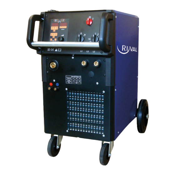
Page 11: Description Of The Appliance
11/29 DESCRIPTION OF THE APPLIANCE MAIN PARTS Fig. 1 - Main parts of Ryval compact aXe Linde AG, Linde Gas Deutschland ©... - Page 12 12/29 Fig. 2 - Main parts of Ryval Separate aXe On/Off Switch Switch coarse Switch smooth Linde AG, Linde Gas Deutschland ©...
- Page 13 Adaptor W (blue) CU aXe Cooling unit Adaptor W (red) Adaptor W (blue) CONTROL PANEL - OVERVIEW Fig. 3 - Ryval 500 aXe control panel PCB - encoder ON / OFF Switch Switch coarse Linde AG, Linde Gas Deutschland ©...
- Page 14 Gas test default RESET (together with button X1) Button Switches between 2S or 4S, Press more than 3s will initiate spot or interval mode Enters secondary parameters (together with button X5) Linde AG, Linde Gas Deutschland ©...
- Page 15 Position of the smooth switch (just SYNERGY) Position of the choke (just SYNERGY) LED – The mode of selecting the program is active (just SYNERGY). Green LED – lights if on the display X8 is displayed material thickness, (just SYNERGY). Linde AG, Linde Gas Deutschland ©...
- Page 16 BASIC CONTROL PANEL Fig. 5 – BASIC control panel On/Off Switch Switch Coarse Switch Fine Wire speed Spot time Interval time LED ON LED thermal protection Switch 2T/4T (optional) Wire insertion Gas test A meter (optional) Linde AG, Linde Gas Deutschland ©...
- Page 17 17/29 V meter (optional) LED over heating WIRE FEEDER Fig 6 – Wire feeder 4 rolls, 2 rolls Pos. Description Fixing shaft Pressure arm Liner- Feeder EURO connector Roll, Plastic cup Linde AG, Linde Gas Deutschland ©...
-
Page 18: Getting Started
1,0-1,2 2062 1,4-1,6 1656 0,8-1,0 2239 Aluminium 1,0-1,2 1829 1,2-1,6 2313 0,8-1,0 2297 Flux core 1,0-1,2 2298 1,2-1,4 2299 1,4-1,6 2534 GETTING STARTED Fig 7 – Earthing cable connecting Quick Connector Male Earthing Clamp Linde AG, Linde Gas Deutschland ©... - Page 19 4. Put the pressure arm E2 down in that way, that the teeth or the gear fit and fix it by setting the lever E1 into vertical position. 5. Adjust the pressure nut that way that it provides constant movement of wire but it does not deform wire. Linde AG, Linde Gas Deutschland ©...
- Page 20 CHANGING THE WIRE FEEDER ROLL 1. Every wire feeding roll in Linde AG, Linde Gas Deutschland machines can be used for two different diameters of welding wire – the rolls have two grooves.
- Page 21 As shielding atmosphere use Argon. Fig 11 – Set for welding aluminium EURO connector Rolls Liner terminal for 4,0mm, 4,7mm outer diameter O – ring 3,5x1,5mm Teflon Liner Sustain pipe for teflon and plastic liner Linde AG, Linde Gas Deutschland ©...
- Page 22 5. Open the F2 cylinder valve 6. Press the button Gas test X2 for digital, V12 for BASIC 7. Adjust the amount of gas on the reduction gas valve (it is not a part of the Linde AG, Linde Gas Deutschland ©...
-
Page 23: Welding
It is necessary to keep the button pressed all the time during welding. The welding stops by releasing the torch button. TWO STROKE BASIC Potentiometers V6 and V7 must be in 0 position. Linde AG, Linde Gas Deutschland ©... - Page 24 INTERVAL WELDING - By means of potentiometer V6 select the time of a spot and by means of potentiometer V7 select the time of an interval (the period during which the machines do not weld) Linde AG, Linde Gas Deutschland ©...
- Page 25 By means of the Encoder you can change the parameter. Use the button X3 to select the next parameter. When you press the button X3, the value of the previous parameter had been stored. Linde AG, Linde Gas Deutschland ©...
- Page 26 1. First left figure – coarse voltage A - B 2. Second left figure - fine voltage 1 - 9, the tenth position of the switch is signed as ”0” 3. Third left figure – choke position. Linde AG, Linde Gas Deutschland ©...
-
Page 27: Routine Maintenance & Inspection
8. A ‘competent person’ must be a person who has acquired through training, qualification or experience, or a combination of them, the knowledge and skills enabling that person to safely carry out a risk assessment and repairs to the electrical equipment in question. Linde AG, Linde Gas Deutschland ©... -
Page 28: Statement Of Warranty
The warranty period begins on the date of sale to the end user. 4. If warranty is being sought, please contact your Linde AG, Linde Gas Deutschland product supplier for the warranty repair procedure. -
Page 29: Disposal
Linde AG, Linde Gas Deutschland ©...
Need help?
Do you have a question about the Ryval 400 aXe and is the answer not in the manual?
Questions and answers