Table of Contents
Advertisement
Quick Links
INSTRUCTIONS FOR OPERATION AND ASSEMBLY
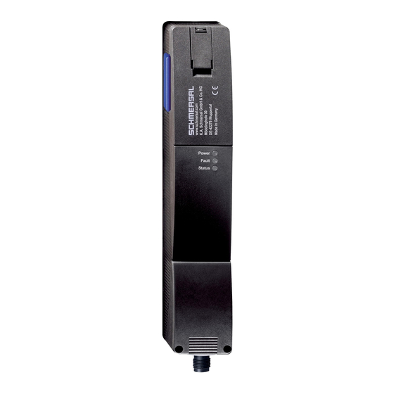
Solenoid interlock AZM201Z-ST2-T-1P2PW-A
Table of Contents
1 About this document
1.1 Function
1 About this document
1.1 Function
This document provides all the information you need for the mounting, set-up and commissioning to ensure the safe
operation and disassembly of the switchgear. The operating instructions enclosed with the device must always be
kept in a legible condition and accessible.
1-22
Advertisement
Table of Contents

Subscribe to Our Youtube Channel
Related Manuals for schmersal AZM201Z-ST2-T-1P2PW-A


Summary of Contents for schmersal AZM201Z-ST2-T-1P2PW-A
-
Page 1: Table Of Contents
INSTRUCTIONS FOR OPERATION AND ASSEMBLY Solenoid interlock AZM201Z-ST2-T-1P2PW-A Table of Contents 1 About this document 1.1 Function 1.2 Target group of the operating instructions: authorised qualified personnel 1.3 Explanation of the symbols used 1.4 Appropriate use 1.5 General safety instructions 2 Product description 2.1 Ordering code... -
Page 2: Target Group Of The Operating Instructions: Authorised Qualified Personnel
The user must observe the safety instructions in this operating instructions manual, the country specific installation standards as well as all prevailing safety regulations and accident prevention rules. Further technical information can be found in the Schmersal catalogues or in the online catalogue on the Internet: products.schmersal.com. -
Page 3: Product Description
2 Product description 2.1 Ordering code Product type description: AZM201(1)-(2)-(3)-T-(4)-(5) Solenoid interlock monitored Actuator monitored without Standard coding Individual coding Individual coding, re-teaching enabled Screw terminals Cage clamps Connector plug M12, 8-pole 1P2PW 1 diagnostic output, p-type and >2 safety outputs, p-type > (combined diagnostic signal: guard system closed and interlock locked) SD2P... -
Page 4: Purpose
For special versions, which are not listed in the ordering code, these specifications apply accordingly, provided that they correspond to the standard version. 2.3 Purpose The non-contact, electronic safety switchgear is designed for application in safety circuits and is used for monitoring the position and locking of movable safety guards. -
Page 5: Technical Data
For safety reasons, invasive work on the device as well as arbitrary repairs, conversions and modifications to the device are strictly forbidden, the manufacturer shall accept no liability for damages resulting from such invasive work, arbitrary repairs, conversions and/or modifications to the device. 2.6 Technical Data Approvals - Standards Certificates... - Page 6 Safety classification Standards EN ISO 13849-1 EN IEC 61508 Safety classification - Interlocking function Performance Level, up to Category PFH value 1.90 x 10⁻⁹ /h PFD value 1.60 x 10⁻⁴ Safety Integrity Level (SIL), suitable for applications in Mission time 20 Year(s) Safety classification - Guard locking function Performance Level, up to...
- Page 7 Termination Connector M12, 8-pole Length of sensor chain, maximum 200 m Note (length of the sensor chain) Cable length and cross-section change the voltage drop dependiing on the output current Note (series-wiring) Unlimited number of devices, oberserve external line fusing, max. 31 devices in case of serial diagnostic SD Mechanical data - Dimensions Length of sensor...
- Page 8 Operating current 1,200 mA Required rated short-circuit current 100 A External wire and device fuse rating 2 A gG Time to readiness, maximum 4,000 ms Switching frequency, maximum 1 Hz Electrical data - Magnet control Designation, Magnet control Switching thresholds -3 V …...
- Page 9 Test pulse interval, typical 1000 ms Test pulse duration, maximum 0.5 ms Classification ZVEI CB24I, Source Classification ZVEI CB24I, Sink Electrical data - Diagnostic outputs Designation, Diagnostic outputs Operating current 50 mA Design of control elements short-circuit proof, p-type Voltage drop U , maximum Voltage, Utilisation category DC-13 24 VDC...
-
Page 10: Mounting
This device complies with the nerve stimulation limits (ISED CNR-102) when operated at a minimum distance of 100 In the event of changes or modifications that have not been expressly approved by K.A. Schmersal GmbH & Co. KG, the user's authorisation to use the device may become ineffective. -
Page 11: Dimensions
Mindestabstand zwischen zwei Sicherheitszuhaltungen bzw. zu anderen Systemen mit gleicher Frequenz (125 kHz): 100 mm Mounting of the solenoid interlock and the actuator Refer to the mounting instructions manual for the corresponding actuator. The actuator must be permanently fitted to the safety guards and protected against displacement by suitable measures (tamperproof screws, gluing, drilling of the screw heads). -
Page 12: Electrical Connection
Legende A: Hilfsentriegelung B: Aktiver RFID-Bereich Metal parts and magnetic fields in the lateral RFID area of the solenoid interlock and the actuator can influence the switching distance or lead to malfunctions. Nachrüstsatz Notentsperrung/Fluchtentriegelung Der Nachrüstsatz dient der nachträglichen Funktionserweiterung der Sicherheitszuhaltung. Bezeichnung Bestellnummer Notentsperrung... -
Page 13: Serial Diagnostic -Sd
100 ms einzustellen. Die Sicherheitseingänge der Auswertung sollten einen Testimpuls von ca. 1 ms ausblenden können. Eine Querschlusserkennung in der Auswertung ist nicht notwendig und ist ggf. auszuschalten. Information for the selection of suitable safety-monitoring modules can be found in the Schmersal catalogues or in the online catalogue on the Internet: products.schmersal.com. -
Page 14: Wiring Configuration And Connector Accessories
The application examples shown are suggestions. They however do not release the user from carefully checking whether the switchgear and its set-up are suitable for the individual application. The application examples shown are suggestions. Anschlussbeispiel 1: Reihenschaltung AZM201 mit konventionellem Diagnoseausgang Bei der Reihenschaltung ist die Brücke 24V-X1-X2 aus allen Geräten bis auf das letzte Gerät zu entfernen. -
Page 15: Anlernen Der Betätiger / Betätigererkennung
Funktion Sicherheitsschaltgerät Pinbelegung Belegung der Farbcodes der Mögl. Farbcode abnehmbaren Schmersal- weiterer Einbausteckers Klemmleisten Steckverbinder handelsübliche ST2, M12, 8- gemäß DIN polig 47100 Steckverbinder gemäß EN 60947-5-2 konventionelle serieller Diagnosefunkti Diagnoseausga Sicherheitseingang 1 Sicherheitsausgang 1 Diagnoseausgang SD-Ausgang Sicherheitseingang 2... -
Page 16: Active Principle And Diagnostic Functions
3. After 10 seconds, brief yellow cyclic flashes (3 Hz) request the switch-off of the operating voltage of the solenoid interlock. (If the voltage is not switched off within 5 minutes, the solenoid interlock cancels the "teach-in" procedure and signals a false actuator by 5 red flashes). 4. - Page 17 be disabled within the duration of risk. After fault rectification, the error message is reset by opening and re-closing the corresponding safety guard. Automatic, electronic locking takes place if more than one fault is detected at the safety outputs or a cross circuit is detected between Y1 and Y2.
- Page 18 18-22...
- Page 19 Table 1: Diagnostic information of the safety switchgear System Diagnostic Magnet control IN Safety outputs Y1, Y2 condition output OUT Power to Power to green yellow AZM201Z AZM201B -1P2PW unlock lock Door open 24 V (0 V) 0 V (24 V) Door closed, 24 V actuator...
-
Page 20: Solenoid Interlock With Serial Diagnostic Function Sd
In this way, the diagnostic signals can be evaluated by means of a PLC. The necessary software for the integration of the SD-Gateway is available for download at products.schmersal.com. The response data and the diagnostic data are automatically and permanently written in an input byte of the PLC for each solenoid interlock in the series-wired chain. -
Page 21: Set-Up And Maintenance
Error warning A fault that does not immediately endanger the safety function of the safety switchgear (e.g. too high ambient temperature, safety output at external potential, cross-circuit) leads to delayed shutdown. This signal combination, diagnostic output disabled and safety channels still enabled, can be used to stop the production process in a controlled manner. -
Page 22: Disassembly And Disposal
£ legislations. 22-22 Schmersal Ltd., Sparrowhawk Close, WR14 1GL Malvern The details and data referred to have been carefully checked. Images may diverge from original. Further technical data can be found in the manual. Technical amendments and errors possible. Generated on: 23/05/2023, 09:53...
Need help?
Do you have a question about the AZM201Z-ST2-T-1P2PW-A and is the answer not in the manual?
Questions and answers