Table of Contents
Advertisement
Quick Links
INSTRUCTIONS FOR OPERATION AND ASSEMBLY
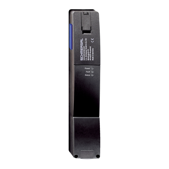
Solenoid interlock AZM201Z-SK-T-SD2P
Table of Contents
1 About this document
1.1 Function
1 About this document
1.1 Function
This document provides all the information you need for the mounting, set-up and commissioning to ensure the safe
operation and disassembly of the switchgear. The operating instructions enclosed with the device must always be
kept in a legible condition and accessible.
1-22
Advertisement
Table of Contents

Subscribe to Our Youtube Channel
Related Manuals for schmersal AZM201Z-SK-T-SD2P


Summary of Contents for schmersal AZM201Z-SK-T-SD2P
-
Page 1: Table Of Contents
INSTRUCTIONS FOR OPERATION AND ASSEMBLY Solenoid interlock AZM201Z-SK-T-SD2P Table of Contents 1 About this document 1.1 Function 1.2 Target group of the operating instructions: authorised qualified personnel 1.3 Explanation of the symbols used 1.4 Appropriate use 1.5 General safety instructions 2 Product description 2.1 Ordering code... -
Page 2: Target Group Of The Operating Instructions: Authorised Qualified Personnel
The user must observe the safety instructions in this operating instructions manual, the country specific installation standards as well as all prevailing safety regulations and accident prevention rules. Further technical information can be found in the Schmersal catalogues or in the online catalogue on the Internet: products.schmersal.com. -
Page 3: Ordering Code
2.1 Ordering code Product type description: AZM201(1)-(2)-(3)-T-(4)-(5) Solenoid interlock monitored Actuator monitored without Standard coding Individual coding Individual coding, re-teaching enabled Screw terminals Cage clamps Connector plug M12, 8-pole 1P2PW 1 diagnostic output, p-type and >2 safety outputs, p-type > (combined diagnostic signal: guard system closed and interlock locked) SD2P... -
Page 4: Warning About Misuse
The non-contact, electronic safety switchgear is designed for application in safety circuits and is used for monitoring the position and locking of movable safety guards. The safety switchgears are classified according to EN ISO 14119 as type 4 interlocking devices. Designs with individual coding are classified as highly coded. -
Page 5: Technical Data
2.6 Technical Data Approvals - Standards Certificates TÜV cULus General data Standards EN ISO 13849-1 EN ISO 14119 EN IEC 60947-5-3 EN IEC 61508 Coding Universal coding Coding level according to EN ISO 14119 Working principle RFID Frequency band RFID 125 kHz Transmitter output RFID, maximum -6 dB/m... - Page 6 Standards EN ISO 13849-1 EN IEC 61508 Safety classification - Interlocking function Performance Level, up to Category PFH value 1.90 x 10⁻⁹ /h PFD value 1.60 x 10⁻⁴ Safety Integrity Level (SIL), suitable for applications in Mission time 20 Year(s) Mechanical data Mechanical life, minimum 1,000,000 Operations...
- Page 7 Wire cross-section, minimum 23 AWG Wire cross-section, maximum 15 AWG Wire cross-section 23 ... 15 AWG Allowed type of cable solid single-wire solid multi-wire flexible Mechanical data - Dimensions Length of sensor 50 mm Width of sensor 40 mm Height of sensor 220 mm Ambient conditions Degree of protection...
- Page 8 Operating current 1,200 mA Required rated short-circuit current 100 A External wire and device fuse rating 4 A gG Time to readiness, maximum 4,000 ms Switching frequency, maximum 1 Hz Electrical data - Magnet control Designation, Magnet control Switching thresholds -3 V …...
- Page 9 Test pulse duration, maximum 0.5 ms Classification ZVEI CB24I, Source Classification ZVEI CB24I, Sink Electrical data - Serial diagnostic SD Designation, Serial diagnostic SD Operation current 150 mA Design of control elements short-circuit proof, p-type Wiring capacitance 50 nF Status indication Note (LED switching conditions display) Operating condition: LED green Error / functional defect: LED red...
-
Page 10: Mounting
This device complies with the nerve stimulation limits (ISED CNR-102) when operated at a minimum distance of 100 In the event of changes or modifications that have not been expressly approved by K.A. Schmersal GmbH & Co. KG, the user's authorisation to use the device may become ineffective. -
Page 11: Dimensions
Hilfsentriegelung Zur Aufstellung der Maschine kann die Sicherheitszuhaltung spannungslos entriegelt werden. Nach Öffnen der Kunststoffklappe „A" (siehe Bild „Abmessungen") wird durch Drehen des Dreikants im Uhrzeigersinn das Sperrmittel in Entriegelungsstellung gebracht. Erst nach Zurückdrehen des Dreikants in die Ausgangslage ist die normale Funktion wieder gegeben. -
Page 12: Electrical Connection
100 ms einzustellen. Die Sicherheitseingänge der Auswertung sollten einen Testimpuls von ca. 1 ms ausblenden können. Eine Querschlusserkennung in der Auswertung ist nicht notwendig und ist ggf. auszuschalten. Information for the selection of suitable safety-monitoring modules can be found in the Schmersal catalogues or in the online catalogue on the Internet: products.schmersal.com. -
Page 13: Serial Diagnostic -Sd
For convenient wiring and series-wiring of SD components, the SD junction boxes PFB-SD-4M12-SD (variant for the field) and PDM-SD-4CC-SD (variant for control cabinet on carrier rail) are available along with additional comprehensive accessories. Detailed information is available on the Internet, products.schmersal.com. 4.3 Wiring examples for series-wiring Der Aufbau einer Reihenschaltung ist möglich. -
Page 14: Wiring Configuration And Connector Accessories
Y1 and Y2 = Safety outputs → Safety monitoring module Anschlussbeispiel 2: Reihenschaltung AZM201 mit serieller Diagnosefunktion (max. 31 Geräte in Reihe) Bei Geräten mit serieller Diagnosefunktion (Bestellindex -SD) werden die seriellen Diagnoseanschlüsse in Reihe geschaltet und zur Auswertung auf ein SD-Gateway geführt. Die Sicherheitsausgänge des ersten Sicherheitsschaltgerätes werden auf die Auswertung geführt. -
Page 15: Anlernen Der Betätiger / Betätigererkennung
Funktion Sicherheitsschaltgerät Pinbelegung Belegung der Farbcodes der Mögl. Farbcode abnehmbaren Schmersal- weiterer Einbausteckers Klemmleisten Steckverbinder handelsübliche ST2, M12, 8- gemäß DIN polig 47100 Steckverbinder gemäß EN 60947-5-2 konventionelle serieller Diagnosefunkti Diagnoseausga Sicherheitseingang 1 Sicherheitsausgang 1 Diagnoseausgang SD-Ausgang Sicherheitseingang 2... -
Page 16: Active Principle And Diagnostic Functions
3. After 10 seconds, brief yellow cyclic flashes (3 Hz) request the switch-off of the operating voltage of the solenoid interlock. (If the voltage is not switched off within 5 minutes, the solenoid interlock cancels the "teach-in" procedure and signals a false actuator by 5 red flashes). 4. - Page 17 be disabled within the duration of risk. After fault rectification, the error message is reset by opening and re-closing the corresponding safety guard. Automatic, electronic locking takes place if more than one fault is detected at the safety outputs or a cross circuit is detected between Y1 and Y2.
- Page 18 18-22...
- Page 19 Table 1: Diagnostic information of the safety switchgear System Diagnostic Magnet control IN Safety outputs Y1, Y2 condition output OUT Power to Power to green yellow AZM201Z AZM201B -1P2PW unlock lock Door open 24 V (0 V) 0 V (24 V) Door closed, 24 V actuator...
-
Page 20: Solenoid Interlock With Serial Diagnostic Function Sd
In this way, the diagnostic signals can be evaluated by means of a PLC. The necessary software for the integration of the SD-Gateway is available for download at products.schmersal.com. The response data and the diagnostic data are automatically and permanently written in an input byte of the PLC for each solenoid interlock in the series-wired chain. -
Page 21: Set-Up And Maintenance
Error warning A fault that does not immediately endanger the safety function of the safety switchgear (e.g. too high ambient temperature, safety output at external potential, cross-circuit) leads to delayed shutdown. This signal combination, diagnostic output disabled and safety channels still enabled, can be used to stop the production process in a controlled manner. -
Page 22: Disassembly And Disposal
£ legislations. 22-22 Schmersal Ltd., Sparrowhawk Close, WR14 1GL Malvern The details and data referred to have been carefully checked. Images may diverge from original. Further technical data can be found in the manual. Technical amendments and errors possible. Generated on: 07/05/2023, 03:56...
Need help?
Do you have a question about the AZM201Z-SK-T-SD2P and is the answer not in the manual?
Questions and answers