Table of Contents
Advertisement
Quick Links
INSTRUKSJONER FOR BRUK OG INSTALLASJON
AZM201Z-ST-T-1P2PW-A-2965-1-DU
Table of Contents
1 About this document
1.1 Function
1 About this document
1.1 Function
This document provides all the information you need for the mounting, set-up and commissioning to ensure the safe
operation and disassembly of the switchgear. The operating instructions enclosed with the device must always be
kept in a legible condition and accessible.
1-22
Advertisement
Table of Contents

Related Manuals for schmersal AZM201Z-ST-T-1P2PW-A-2965-1-DU


Summary of Contents for schmersal AZM201Z-ST-T-1P2PW-A-2965-1-DU
-
Page 1: Table Of Contents
INSTRUKSJONER FOR BRUK OG INSTALLASJON AZM201Z-ST-T-1P2PW-A-2965-1-DU Table of Contents 1 About this document 1.1 Function 1.2 Target group of the operating instructions: authorised qualified personnel 1.3 Explanation of the symbols used 1.4 Appropriate use 1.5 General safety instructions 2 Product description 2.1 Ordering code... -
Page 2: Target Group Of The Operating Instructions: Authorised Qualified Personnel
The user must observe the safety instructions in this operating instructions manual, the country specific installation standards as well as all prevailing safety regulations and accident prevention rules. Further technical information can be found in the Schmersal catalogues or in the online catalogue on the Internet: products.schmersal.com. -
Page 3: Product Description
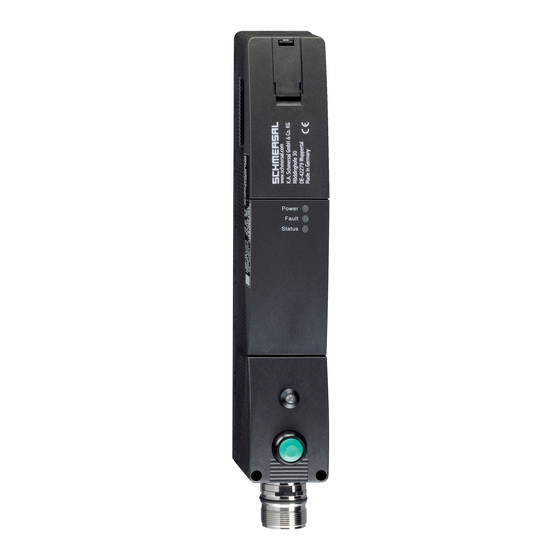
2 Product description 2.1 Ordering code Produkt-typebetegnelse: AZM201(1)-(2)-(3)-T-(4)-(5) Overvåket av magnetisk forrigling Overvåket av aktuator uten standard kodet individuelt kodet individuelt kodet, kan innlæres på nytt Skruetilslutning Bæreklemmer Konnektorplugg M12, 8-polet 1P2PW 1 diagnoseutgang, p-type og 2 sikkerhetsutganger, p-type > (kombinert diagnosesignal: lukket sikkerhetsinnretning og låst vakt lukket og tilholder) SD2P... -
Page 4: Purpose
For special versions, which are not listed in the ordering code, these specifications apply accordingly, provided that they correspond to the standard version. 2.3 Purpose The non-contact, electronic safety switchgear is designed for application in safety circuits and is used for monitoring the position and locking of movable safety guards. -
Page 5: Technical Data
For safety reasons, invasive work on the device as well as arbitrary repairs, conversions and modifications to the device are strictly forbidden, the manufacturer shall accept no liability for damages resulting from such invasive work, arbitrary repairs, conversions and/or modifications to the device. 2.6 Technical Data Tillatelser - Standard Data... - Page 6 Klassifisering Standarder, forskrifter EN ISO 13849-1 EN IEC 61508 Klassifisering - sikkerhetslåsfunksjon Performance Level, up to Kontrollkategori PFH-verdi 1,90 x 10⁻⁹ /h PFD-verdi 1,60 x 10⁻⁴ Safety Integrity Level (SIL), suitable for applications in Mission time 20 år Klassifisering - forriglingsfunksjon Performance Level, up to Kontrollkategori PFH-verdi...
- Page 7 Konnektor stikk Konnektor M23, 12-polet Length of sensor chain, maximum 200 m Note (length of the sensor chain) Cable length and cross-section change the voltage drop dependiing on the output current Note (series-wiring) Unlimited number of devices, oberserve external line fusing, max. 31 devices in case of serial diagnostic SD Wire cross-section 23 ...
- Page 8 Rated operating voltage 24 VDC driftssstrøm 1 200 mA Nødvendig nominell kortslutningsstrøm iht EN 60947-5-1 100 A External wire and device fuse rating 3 A gG Tid til beredskap , maksimum 4 000 ms Brytefrekvens, maksimum 1 Hz Elektriske data - Solenoidkontroll INN Designation, Magnet control Koblingsterskeler for magnetinnganger -3 V …...
- Page 9 Current, Utilisation category DC-13 0,25 A Test pulse interval, typical 1000 ms Test pulse duration, maximum 0,5 ms Classification ZVEI CB24I, Source Classification ZVEI CB24I, Sink Elektriske data - diagnoseutgang Designation, Diagnostic outputs Driftssstrøm (diagnose-utgang) 50 mA Design of control elements short-circuit proof, p-type Voltage drop U , maximum...
-
Page 10: Mounting
This device complies with the nerve stimulation limits (ISED CNR-102) when operated at a minimum distance of 100 In the event of changes or modifications that have not been expressly approved by K.A. Schmersal GmbH & Co. KG, the user's authorisation to use the device may become ineffective. - Page 11 For fitting the solenoid interlock, two mounting holes for M6 screws with washers (washers included in delivery) are provided. The solenoid interlock must not be used as an end stop. Any mounting position. The mounting position however must be chosen so that the ingress of dirt and soiling in the used opening is avoided. The unused actuator opening must be sealed by means of the dust-proof flap (included in delivery).
-
Page 12: Dimensions
3.2 Dimensions All measurements in mm. Legende A: Hilfsentriegelung B: Aktiver RFID-Bereich Metal parts and magnetic fields in the lateral RFID area of the solenoid interlock and the actuator can influence the switching distance or lead to malfunctions. Nachrüstsatz Notentsperrung/Fluchtentriegelung Der Nachrüstsatz dient der nachträglichen Funktionserweiterung der Sicherheitszuhaltung. -
Page 13: Serial Diagnostic -Sd
100 ms einzustellen. Die Sicherheitseingänge der Auswertung sollten einen Testimpuls von ca. 1 ms ausblenden können. Eine Querschlusserkennung in der Auswertung ist nicht notwendig und ist ggf. auszuschalten. Information for the selection of suitable safety-monitoring modules can be found in the Schmersal catalogues or in the online catalogue on the Internet: products.schmersal.com. -
Page 14: Wiring Configuration And Connector Accessories
Der Aufbau einer Reihenschaltung ist möglich. Bei einer Reihenschaltung bleibt die Risikozeit unverändert und die Reaktionszeit erhöht sich um die Summe der in den technischen Daten angegebenen Reaktionszeit der Eingänge pro zusätzlichem Gerät. Die Anzahl der Geräte ist lediglich durch die Leitungsverluste und die externe Leitungsabsicherung, gemäß... -
Page 15: Anlernen Der Betätiger / Betätigererkennung
Funktion Sicherheitsschaltgerät Pinbelegung Belegung der Farbcodes der Mögl. Farbcode abnehmbaren Schmersal- weiterer Einbausteckers Klemmleisten Steckverbinder handelsübliche ST2, M12, 8- gemäß DIN polig 47100 Steckverbinder gemäß EN 60947-5-2 konventionelle serieller Diagnosefunkti Diagnoseausga Sicherheitseingang 1 Sicherheitsausgang 1 Diagnoseausgan SD-Ausgang Sicherheitseingang 2... -
Page 16: Active Principle And Diagnostic Functions
2. Introduce the actuator in the detection range. The teach-in procedure is signalled at the solenoid interlock, green LED off, red LED on, yellow LED flashes (1 Hz). 3. After 10 seconds, brief yellow cyclic flashes (3 Hz) request the switch-off of the operating voltage of the solenoid interlock. - Page 17 Error Errors which no longer guarantee the function of the safety switchgear (internal errors) cause the safety outputs to be disabled within the duration of risk. After fault rectification, the error message is reset by opening and re-closing the corresponding safety guard. Automatic, electronic locking takes place if more than one fault is detected at the safety outputs or a cross circuit is detected between Y1 and Y2.
- Page 18 18-22...
- Page 19 Table 1: Diagnostic information of the safety switchgear System Diagnostic Magnet control IN Safety outputs Y1, Y2 condition output OUT Power to Power to green yellow AZM201Z AZM201B -1P2PW unlock lock Door open 24 V (0 V) 0 V (24 V) Door closed, 24 V actuator...
-
Page 20: Solenoid Interlock With Serial Diagnostic Function Sd
In this way, the diagnostic signals can be evaluated by means of a PLC. The necessary software for the integration of the SD-Gateway is available for download at products.schmersal.com. The response data and the diagnostic data are automatically and permanently written in an input byte of the PLC for each solenoid interlock in the series-wired chain. -
Page 21: Set-Up And Maintenance
Error warning A fault that does not immediately endanger the safety function of the safety switchgear (e.g. too high ambient temperature, safety output at external potential, cross-circuit) leads to delayed shutdown. This signal combination, diagnostic output disabled and safety channels still enabled, can be used to stop the production process in a controlled manner. -
Page 22: Disassembly And Disposal
22-22 Schmersal Nordiska AB, F O Petersons gata 28, S-421 31 Västra Frölunda Data og verdier er kontrollert omhyggelig. Bilder kan avvike fra originalen. Ytterligere tekniske data finner du i manualen. Tekniske modifiseringer og feil kan forkomme. Generert til 11.06.2023, 19:28...