Table of Contents
Advertisement
Quick Links
Advertisement
Table of Contents

Subscribe to Our Youtube Channel
Related Manuals for Hanna Instruments EC Series


Summary of Contents for Hanna Instruments EC Series
- Page 1 BL983313 • BL983317 • BL983320 • BL983322 • BL983327 EC Process Mini Controller Series BL983315 • BL983318 • BL983319 • BL983321 • BL983324 • BL983329 TDS Process Mini Controller Series Hanna Instruments Inc., 584 Park East Drive, Woonsocket, RI 02895 USA www.hannainst.com...
-
Page 2: Table Of Contents
All rights are reserved. Reproduction in whole or in part is prohibited without the written consent of the copyright owner, Hanna Instruments Inc., Woonsocket, Rhode Island, 02895, USA. Hanna Instruments reserves the right to modify the design, construction, or appearance of its products without advance notice. -
Page 3: Preliminary Examination
Preliminary Examination 1. PRELIMINARY EXAMINATION Remove the instrument and accessories from the packaging and examine it carefully. For further assistance, please contact your local Hanna Instruments office or email us at tech@hannainst.com. Each instrument is supplied with: • Mounting brackets •... -
Page 4: Controller Specifications
Controller Specifications... -
Page 5: Probe Specifications
Probe Specifications 5. PROBE SPECIFICATIONS HI7632‑00 HI7634‑00 probes are sold separately. HI7632-00 HI7634-00 Type Two‑pole Amperometric 4.7 KΩ – NTC sensor 9.4 KΩ – Cell constant 1 cm¯ Materials PVC body; AISI 316 electrodes Temperature 5 to 50 °C (41 to 122 °F) ... -
Page 6: Functional Description
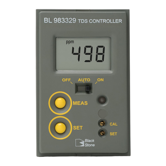
Functional Description 6. FUNCTIONAL DESCRIPTION 6.1. FRONT PANEL 1. LCD 2. Dosing switch • OFF (dosing disabled) • AUTO (automatic dosing, setpoint value) • ON (dosing enabled) 3. MEAS key (measurement mode) AUTO 4. SET key (configure display value) 5. SET trimmer (adjust setpoint value) MEAS 6. -
Page 7: Installation
Installation 7. INSTALLATION 7.1. UNIT MOUNT Front view Side view Top view outside panel cutout mounting bracket & inside depth mounting bracket 0.25/4 mm Mounting Adjustable (0.01/0.16”) Bracket Location Bracket 81 mm (3.2”) 43 mm (1.7”) 95 mm (3.7”) MIN 53 mm (2.0”) WARNINGS Time... -
Page 8: Operations
Operations Overtime feature (system control) • This feature is provided to set the maximum continuous time the relay is running a pump or valve, by adjusting the trimmer (from approx. 5 minutes minimum, to approx. 30 minutes maximum). Time • When the set time expires, dosing stops, the LED operational indicator turns red (blinking), and “TIMEOUT”... -
Page 9: Setpoint Configuration
Operations 8.2. SETPOINT CONFIGURATION General: a set point is a threshold value that will trigger control if the measurement value crosses it. 1. Press the SET key. The LCD displays the default or previously configured value along with the ”SET“ tag. 2. -
Page 10: Accessories
If under warranty, report the model number, date of purchase, serial number and the nature of the problem. If the repair is not covered by the warranty, you will be notified of the charges incurred. If the instrument is to be returned to Hanna Instruments office, first obtain a Returned Goods Authorization (RGA) number from the Technical Service department and then send it with shipping costs prepaid.
Need help?
Do you have a question about the EC Series and is the answer not in the manual?
Questions and answers