Table of Contents
Advertisement
Quick Links
Advertisement
Table of Contents

Related Manuals for Hanna Instruments BL121 Series


Summary of Contents for Hanna Instruments BL121 Series
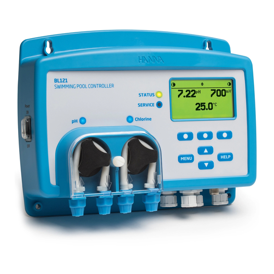
- Page 1 BL121 SWIMMING POOL CONTROLLER...
-
Page 2: Table Of Contents
Hanna representative near you at www.hannainst.com. All rights are reserved. Reproduction in whole or in part is prohibited without the written consent of the copyright owner, Hanna Instruments Inc., Woonsocket, Rhode Island, 02895 , USA Pool Controller Contents ................................3... -
Page 3: Table Of Pool Controller Contents
Pool This product is intended to maintain disinfectant and pH levels at a desired level in swimming pools. Remove the instrument and accessories from the packaging and verify that no damage has occurred during shipping. Remove the Controller protective film from meter. Notify your nearest Hanna Customer Service Center if items are missing or damaged. Contents Two versions are available: In-line BL121-10 and Flow-cell BL121-20. -
Page 4: Description
Description The Swimming Pool Controller is an automatic system to measure and control levels of pH and free chlorine in a swimming pool or a spa. The chlorine level is measured based on the ORP of REDOX principle. An increase of the ORP value correlates with an increase of the level of free chlorine. -
Page 5: Controller Overview
Controller Overview Product Diagram Front Panel 1. Power Switch 11. Keyboard Area 2. Acid Dosing Pump 12. USB port (host) 13. Liquid Crystal Display (LCD) 3. IN Acid 4. OUT Acid 14. LED Area 5. Leakage holes 15. LED Status 6. -
Page 6: Connections, Alarm, Output And Power
Connections, 4 - 20 mA OUT Alarm, ANALOG Output 4 - 20 mA OUT OUTPUTS and Power 4 - 20 mA OUT DIGITAL INPUTS ALARM RELAY Neutral POWER INPUT Protective Earth Line Warning! Always disconnect power to the Pool Controller when making electrical connections. Gland Seals for Power Cable. -
Page 7: Keypad Function
Keypad Function 1. MENU Key - Access to manual pump control, pH/ORP/Temperature options and General setup 2. p/q Key - In menu mode scroll the menu items / adjust the settings. In measurement mode changes the screen: three parameter screen (pH, ORP, and Temperature), single parameter screen and plot display. -
Page 8: Pool Controller Install
Pool Controller Install Setup/Installation... - Page 9 Pool Controller Install Connection for flow detector is optional. Connection for low level sensor for acid tank is optional. Connection for low level sensor for chlorine tank is optional. Probe connector. Setup/Installation...
- Page 10 Pool Controller Install With a Phillips head screwdriver remove the screw, after opening lift the back cover and remove it. To insert in place, attach the bottom part of the cover to the controller and push to close. Tight the screw with the screwdriver. Setup/Installation...
- Page 11 Pool Installation Guidelines - Shield the controller from direct sunlight, dripping water and excess vibrations. Controller - Keep flow rate as constant as possible for optimum sensor operation. Install - The sample analyzed should be representative of entire pool. • Check the tanks level. •...
-
Page 12: Saddle Installation
Saddle Saddles are used for the probe installation in an in-line installation, and for injector installations in both in-line and flow- cell installations. Select pipe locations that are accessible with sensor cable length and tubing. Installation Saddle for Probe (in-line) Saddle threat size Drill size Min. -
Page 13: Probe Installation
Probe Installation 3.Insert the nut on the 2.Remove protective cap and probe. verify if the o-ring is in place. 5.Insert the prepared probe 4.Screw carefully the adapter with the adapter and on the probe. Do not to screw it carefully into damage the o-ring. -
Page 14: Installing Aspiration Filters
Installing Aspiration filters are used in the reagent tanks to filter debris from entering the Aspiration tubing. Filters 1. Cut required length of suction/injection tubing to reach between peristaltic pump and reagent tanks. 2. Place the aspiration filter weight and the compression fitting nut on the tubing. 3. -
Page 15: Flow-Cell Installation
Flow-Cell Installation Prepare the aspiration and dispensing valve assemblies like in the above drawing following the next steps: 1. Insert two o-ring’s (2) on the nipple (1) from both side. 2. Screw the nipple in the saddle (3). 3. Screw the valve (4) in the open end on the nipple screwed in the saddle until is tight and oriented in front to be operated. - Page 16 Flow-Cell Installation The flow cell will be mounted in the following order: - Take one o-ring (4) and mount on the flow-cell cap (5). Insert these on flow-cell tube (2) on the far end from lateral hole. Mount one flow-cell nut (3) by screwing over the flow cell cap.
-
Page 17: Controller Menu
Controller The controller menu is grouped into five categories: • Manual/Auto pump control Menu • pH Options (CAL, Setup, GLP) • ORP Options (CAL, Setup, GLP) • Temperature Options (Setup) • General Manual/Auto Pump Control Each pump can be set to MANUAL control by selecting the On 10s/OFF options. When On 10s is selected the pump runs continuously for 10 s. - Page 18 Controller ORP Options Menu Option Choices / Resolution Default Note Set Point 200 to 900 mV / 1 mV 700 mV Use to set the expected ORP level in pool. ORP regulated time proportional band. Proportions the time off and time on within the Proportional band 10 to 200 mV / 1 mV 100 mV...
- Page 19 Controller Option Choices / Resolution Default Note Menu Alarm Activates Enable Enable/Disable the relay control for Temperature Disable Relay Disable events Unit °C / °F °C Temperature measurement unit Analog Out Disabled, AO1, AO2, AO3 Disabled Assign an analog output to Temperature reading -4.0 °C to 105.0 °C / 0.1 °C 105.0 °C Max.
-
Page 20: User Interface Map
User Interface Setup/Installation... -
Page 21: User Interface In Parameter Setup
User Interface in Parameter Setup User Interface in General Setup Setup/Installation... -
Page 22: Operational Guide
Operational Start the recirculation pump. Verify flow-cell fills and empties. After Setting up the Pump Controller, probe and all associated accessories the controller Guide is ready to test. Turn on the controller by switching ON/OFF button. After initialization Measure has been completed, the controller displays the measurement screen. If the controller was left in Manual (OFF or ON 10s) mode before turning OFF, the following screen will be displayed at startup. -
Page 23: Ph Calibration
The BL121 can calibrate the pH probe using an Automatic, two points from three available values (4.01, 7.01, 10.01 pH) calibration. If the buffer calibration was made a process calibration can be performed in one adjustable point. Calibration The probe should be calibrated: •... - Page 24 The Error messages in buffer calibration are the followings: Calibration Wrong Buffer: This message appears when the difference between the pH reading and the value of the selected buffer is too great. If this error message is displayed, check if you have selected the proper calibration buffer and have poured the desired buffer.
-
Page 25: Orp Calibration
The pH calibration is affected by pH buffers contamination that could appear if the probe was used in ORP standard solution. It is recommanded to perform the pH calibration first. Calibration Pour calibration solutions into clean beakers. If possible, use plastic to minimize any EMC interferences. For accurate calibration and to minimize cross-contamination, use two beakers;... -
Page 26: Controller Modes
Controller The following table describes the status of LED’s, dosing pumps, measurement and logging processes in different BL121 controller modes. Modes 2016-02-22 LEDs Dosing pumps Modes Events With dosing delay at start-up Auto-Off Auto-Off No dosing ☼... - Page 27 The control mode is the normal operational mode for BL121. During control mode BL121 fulfills the following main tasks: Control • reads the data from HI1036 combined probe, converts the data to measurements and displays them on the LCD. Mode •...
- Page 28 Control A complete description of pH and ORP regulators connections is described in the picture below: Mode LEDs status: STATUS; SERVICE; pH/Chlorine (controlling and pump off) (controlling and pump run) Relay is energized. (No alarms) Analog outputs follow the assigned parameters based on settings. Operational Guide...
-
Page 29: Control Mode
Control Reagent Pumps are disabled: • Immediately after power-on for a period of time defined in pH/ORP Setup. Mode • When pH pump is manually controlled (the ORP control is in wait mode). • If one or more high/low alarms and/or process errors are active. •... -
Page 30: Logging
Logging The BL121 logging system offers an automatic save mode that includes all important parameters (pH, ORP, Temperature) and the following events: • High and Low alarms • Overdosing Errors • Hold Input events • Low Level Tank Events • Manual Mode •... - Page 31 Log Recall • By pressing 1/3, 2/3 and 3/3 other details will be displayed. In every moment the Plot can be activated by pressing Plot. • If in the Log Recall Summary screen the Option key is pressed, the following screen is displayed.
-
Page 32: Analog Outputs
Analog The meter is provided with three 4-20 mA isolated current outputs that are factory calibrated. Outputs It is possible to configure each output through the Menu as pH/ORP or Temperature outputs. The analog output menus are illustrated below: Each output can be disabled or configured to a parameter and may be connected to a chart recorder or data logger. The current signal is proportional to the assigned scale of the assigned parameter (e.g. -
Page 33: Events Management
The BL121 controller has implemented an intuitive and user friendly events management that allows a quick and easy Events identification of event sources. Management The signalizing is done by STATUS and SERVICE LEDs located on the controller front panel and by ALARM relay status. The STATUS LED is a multicolor Red-Yellow-Green LED that indicates the controller status based on traffic light concept (... - Page 34 Events Note: The logging period is higher than the measure period. Any alarm condition that occurred between logging moments are captured and logged even if the alarm conditions are no longer active on first log (event) after the alarm Management •...
- Page 35 · HOLD -Hold input (recirculation pump) · The Help of measurement screens will display the active errors. System Errors Events These types of events are continuously monitored and if one or more occurred it will put the controller in ERROR mode to Management avoid unpredictable controller behavior.
- Page 36 Specifications 0.00 to 14.00 pH Range ±2000 mV -5.0 to 105.0 ºC (23.0 to 221.0 °F) 0.01 pH Resolution 1 mV 0.1 °C (0.1 ºF) ±0.05 pH Accuracy ±5 mV @ 25 °C / 77 °F ±1 ºC (±1.8 ºF) pH buffer calibration: Automatic, two points (4.01, 7.01, 10.01 pH) Calibration pH process calibration: Single point, adjustable...
-
Page 37: Specifications
Specifications Additional Specifications Pump speed control (0.5 L/h to 3.5 L/h) Pump Control Manual control of each pump Intuitive alert system based on LED’s Alarm System Alarm filtering options Alarm relay control based on user setup filters Password Protection The setup, calibration and log recall features are password protected Storage Interface USB pH/ORP Alarm Relay Output... -
Page 38: Maintenance
Electrode PREPARATION Conditioning Remove the electrode protective cap. DO NOT BE ALARMED IF ANY SALT DEPOSITS ARE PRESENT. Maintenance This is normal with electrodes and they will disappear when rinsed with water. During transport tiny bubbles of air may have formed inside the glass bulb. The electrode cannot function properly under these conditions. -
Page 39: Accessories
CONTROLLERS/PROBES Accessories pH/ORP/Temperature Pool pH/ORP/Temperature Pool Controller, 115/230 V Controller with Flow-cell, with all the components 115/230 V with all the mentioned on page 3 components mentioned on BL121-10 page 3 BL121-20 Industrial pH/ORP/ Fittings Kit for 50 mm pipe Temperature/Matching Pin diameter. - Page 40 Accessories Injector saddle for Pool Controller peristaltic 75 mm pipe diameter, ½" pump tubing kit (2 pcs.) thread BL120-300 BL120-275 Pool Controller peristaltic Pool Controller pump cover pump rotor with screw BL120-301 BL120-302 Flow-cell probe adapter kit Flow-cell valve BL120-400 BL120-401 Flow-cell tubing (10 m) Flow-cell kit for 50 mm pipe...
- Page 41 Accessories USB protective cap BL121 Simulator BL120-902 BL120-901 Cable gland protective kit (6 pcs.) BL120-903 HI 740036P Plastic Beaker Set, 100 mL (10 pcs.) ELECTRODE STORAGE SOLUTIONS HI 70300L Storage Solution, 500 mL BUFFER SOLUTIONS HI 70004P pH 4.01 Buffer Sachets, 20 mL (25 pcs.) HI 70007P pH 7.01 Buffer Sachets, 20 mL (25 pcs.) HI 70010P...
-
Page 42: Warranty
If the repair is not covered by the warranty, you will be notified of the charges incurred. If the instrument is to be returned to Hanna Instruments, first obtain a Returned Goods Authorization number from the Technical Service department and then send it with shipping costs prepaid. - Page 44 Hanna Instruments Inc. Highland Industrial Park 584 Park East Drive Woonsocket, RI 02895 USA Technical Support for Customers Tel. (800) 426 6287 Fax (401) 765 7575 E-mail tech@hannainst.com www.hannainst.com Printed in ROMANIA MANBL121 09/16-1...
Need help?
Do you have a question about the BL121 Series and is the answer not in the manual?
Questions and answers