
Related Manuals for Taurus TF-S118


Summary of Contents for Taurus TF-S118
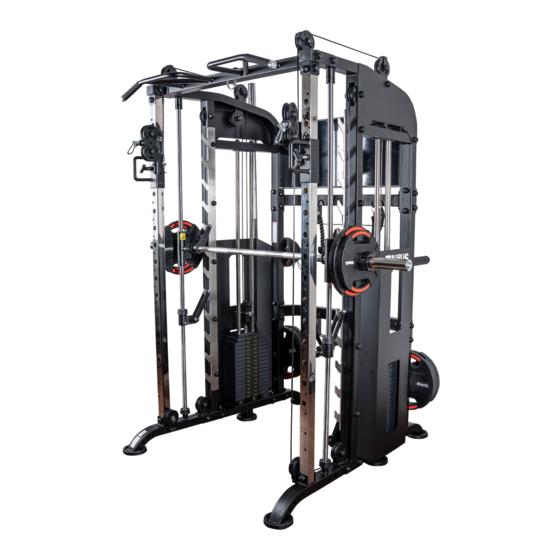
- Page 1 Assembly and Operating Instructions ~ 330 Min. 445 kg L 147 | W 188 | H 219 TFS118.01.02 Art. No. TF-S118 Taurus Universal Smith Machine...
- Page 2 Universal Smith Machine...
-
Page 3: Table Of Contents
Content GENERAL INFORMATION Technical Data Personal Safety Set-Up Place ASSEMBLY General Instructions Scope of Delivery Assembly STORAGE AND TRANSPORT General Instructions TROUBLESHOOTING, CARE AND MAINTENANCE General Instructions Faults and Fault Diagnosis Maintenance and Inspection Calendar DISPOSAL RECOMMENDED ACCESSORIES ORDERING SPARE PARTS Serial Number and Model Name Parts List Exploded Drawing... - Page 4 Universal Smith Machine...
- Page 5 With Taurus® fitness equipment, the focus is on what sport is all about: maximum performance! Therefore, the equipment is developed in close consultation with athletes and sports scientists.
- Page 6 ABOUT THIS MANUAL Please carefully read the entire manual before installation and first use. The manual will help you to quickly set up the system and explains how to safely use it. Make sure that all persons exercising with the equipment (especially children and persons with physical, sensory, mental or motor disabilities) are informed about this manual and its contents in advance.
-
Page 7: General Information
GENERAL INFORMATION Technical Data Weight and Dimensions: Packaging dimensions (L x W x H) and article weight (gross, incl. packaging) approx.: Box 1: 212 cm x 105 cm x 36 cm 309.38 kg Box 2: 62 cm x 51 cm x 22 cm 210 kg Article weight (net, without packaging): 445 kg... -
Page 8: Personal Safety
Personal Safety DANGER ⚠ Before you start using the equipment, you should consult your physician that this type of exercise is suitable for you from a health perspective. Particularly affected are persons who: have a hereditary disposition to high blood pressure or heart disease, are over the age of 45, smoke, have high cholesterol values, are overweight and/or have not exercised regularly in the past year. -
Page 9: Set-Up Place
Set-Up Place WARNING ⚠ Do not place the equipment in main corridors or escape routes. ⚠ CAUTION Choose a location in which to place the equipment such that there is enough free space/ clearance to the front, the rear and to the sides of the equipment. The training room should be well ventilated during training and not be exposed to any draughts. -
Page 10: Assembly
ASSEMBLY General Instructions ⚠ DANGER Do not leave any tools, packaging materials such as foils or small parts lying around, as otherwise there is a danger of suffocation for children. Keep children away from the equipment during assembly. ⚠ WARNING Pay attention to the instructions attached to the equipment in order to reduce the risk of injuries. - Page 11 (1) Left base frame 1x (8) Front connection tube 2x (2) Right frame 1x (14) Plastic cover 160x (3) Left frame 1x (15) Hanging ring 1x (4) Right base frame 1x (18) L shape plate 2x (5) Back connection tube 2x (21) Left upright frame 1x (6) Reinforcing plate (big) 6x (7) Reinforcing plate (small) 2x...
- Page 12 (23) Left upright board 1x (31) cover 2x (32) Pulley catch plate 4x (24) Right upright board 1x (25) Right bearing frame 1x (33) Guide rod 2x (26) Left bearing frame 1x (34) Guide rod lock sleeve 2x (35) Safety hook left 1x (27) Barbell rod 1x (36) Safety hook right 1x (28) Barbell rod ring 2x...
- Page 13 (44) Rubber cushion 4x (47) Rubber cushion 4x (58) Shield 2x (48) guide rod 4x (59) Barbell plate holder 4x (45) weight plate 28x (45+46+49) top weight plate pre-assembled with weight plate and selector rod 2x (60) Hook 6x (52) Cable 2x (62) T shape pin 10x (54) Pulley (big) 12x (55) Pulley (small) 2x...
- Page 14 (64) Lat pull down roller 1x (69) Spotting arm right 1x (65) J hook right 1x (70) T shape pin 1x (71) Dip bar right 1x (66) J hook left 1x (72) Dip bar left 1x (73 & 99) Pulley handle with chain 2x (67) Barbell rod storage 1x (74) Footplate 1x...
- Page 15 (77) Ankle cuff 1x (85) Board 1x (78) V bar 1x (87) Spring collar 8x (79) Close grip rowing handle 1x (88) Selector rod with barbell holder 2x (89) Push rod 1x (80) Straight bar 1x (81) Lat pull bar 2x (90) Connection part 2x (91) Upright frame right 1x (82) Abdominal harness 1x...
- Page 16 (94) Footplate small 1x (95) Shaft 2x (98) Iron handle 2x (100) Pulley bracket 2x (101) Weight stack pin 2x Universal Smith Machine...
-
Page 17: Assembly
Assembly Before assembly, take a close look at the individual assembly steps shown and carry out the assembly in the order given. NOTICE First loosely screw all parts together and check that they fit properly. Tighten the screws using the tool only when you are instructed to do so. If you have difficulty recognising the graphics, we recommend that you open and/or download the PDF instructions stored in the webshop on your end device (e.g. - Page 18 Step 1: Assembly of the Main Frame, Part 1 NOTICE Do not tighten the bolts and nuts yet. Otherwise the components might not fit. Once tightened, each bolt connection must be capped with plastic covers (14) like shown. Attach the left and right frames (3 & 2) to the left and right base frame (1 & 4): Assembly step 1 1.1.
- Page 19 Step 2: Assembly of the Main Frame, Part 2 NOTICE Do not tighten the bolts and nuts yet. Otherwise the components might not fit. Once tightened, each bolt connection must be capped with plastic covers (14) like shown. Attach the upper back link tube (5) to the rear struts of the left and right frames (3 & 2): 1.1.
- Page 20 Step 3: Assembly of the Main Frame, Part 3 Attach the front link tube (8) to the left and right frame (3 & 2) with two bolts (12), one big reinforcing plate (6), four washers (11), two nuts (10) and four plastic covers (14) on each frame. Attach the hanging ring (15) to the front link tube (8) with two washers (17), two nuts (16) and two plastic covers (14).
- Page 22 Step 4: Assembly of the Upright Frames, Bearing Frames and Upright Boards NOTICE The pulleys on the bearing frames (25 & 26) should be oriented inwards. The scales on the upright frames (21 & 22) should be oriented forwards and outwards. Connect the components loosely first and tighten bolts and nuts only when all components are connected.
- Page 23 Assembly step 2...
- Page 24 Step 5: Assembly of the Guide Rods and Barbell Rod CAUTION ⚠ The rods (33 & 27) are lubricated. ࣑ ATTENTION The required rubber cushions (44) are slightly tapered and must be aligned according to the following drawing: Slide the components onto both guide rods (33) in the following order (33): rubber cushion (44), safety hook (35 - left;...
- Page 25 Assembly step 3...
- Page 26 Step 6: Assembly of the Weight Stacks Slide one rubber cushion (47) over each of the four guide rods (48). Insert the guide rods (48) into the left and right base frames (1 & 4). CAUTION ⚠ Guide only one weight plate at a time over the guide rods. NOTICE Begin with the weight plate with the highest number and continue accordingly.
- Page 27 For added weight, install the optional selector with barbell holders (88) instead of the regular pulley bracket (100).
- Page 28 Step 7: Assembly of the Cables and Pulleys NOTICE The cable routing must be performed while simultaneously attaching the pulleys. The following steps show the assembly and cable routing on the right side of the machine. The procedure must be repeated on the left side as well. The following steps show the assembly with the regular pulley holder (F).
- Page 29 Assembly step 5 Assembly step 5 Assembly s (shown on left bearing frame) Descrip�on Note Qty. lock nut big gasket Φ10 Descrip�on Note Qty. hexagon bolt M10*90 lock nut plas�c cover big gasket Φ10 hexagon bolt M10*50 hexagon bolt M10*90 cover Remove the plastic covers, bolt, nut and washers.
- Page 30 Step 8: Cable Adjustment You can recognize the correct cable tension when the top weight plate rests very lightly on the weight stack. If the top weight plate is hanging in the air, the cable is too tight. If the cable is visibly slacking, it is too loose.
- Page 31 Once the cable tension is correctly adjusted, make sure to tighten the pulley in the pulley bracket (100 or 88).
- Page 32 Step 9: Assembly of the Shields, Part 1 ࣑ ATTENTION If you have installed the selector rod with barbell holders (88), the shields (58) cannot be installed. The shields (58) must partly be attached from the inside of the shields (58). Please refer to figure A for a more detailed overview and order of the components.
- Page 34 Step 10: Assembly of the Shields, Part 2 Attach six hooks (60) to the back link tubes (5) with one washer (17) and one nut (16) each. Tighten the nuts and cap with one plastic cover (14) each. NOTICE The board (85) must be attached from the inside. Please refer to figure B for a more detailed overview and order of the components.
- Page 35 ly step 6 Fig. B 86 17 Assembly step 6 86 17...
- Page 36 Step 11: Assembly of the Accessories, Part 1 This Universal Smith Machine offers a wide variety of accessories for an ambitious training. The accessories can be used interchangeable and as required. Attach the barbell rod storage (67) to the left base frame (1) in the rearmost two holes with two bolts (12), four washers (11) and two nuts (10).
- Page 38 Step 12: Assembly of the Accessories, Part 2 NOTICE The footplate (74) has a recess on the bottom side. This is intended for the barbell rod. Attach the footplate (74) to the barbell rod (27) with a total of four T-shaped pins (62). Universal Smith Machine...
- Page 39 Step 13: Assembly of the Accessories, Part 3 Insert the four L-shaped pins (83) into the holes on the base frames (1 & 4). The following accesorries can either be attached to the cable end with snap hooks when training or hung from the hooks for space-saving storage: 75: triceps rope 76: function training bar...
- Page 40 Step 14: Assembly of the Accessories, Part 4 Attach the small footplate (94) to the base frames (1 & 4) with two T-shaped pins (62). ࣑ ATTENTION Before using the jammer arms, the bearing frames must be pushed to the lowest position. Insert the link parts (90) into the uppermost hole of the upright frames (21 &...
- Page 42 Step 15: Subsequent Replacement of the Pulley Holders It is possible to replace the pulley holders connected to the weight stacks at a later stage. If already attached, first remove the shields (58) by loosening all bolts, washers and nuts. ⚠...
- Page 43 Selector rod replacement instruc�on Step 16: Lubricating the Guide Rods No. Descrip�on Note Qty. Before you start exercising, you must lubricate the guide rods for the weight stacks. You can use a selector rod with barbell holder grease-free silicone spray. Take a lint-free cloth such as kitchen paper and hold it in your hand behind the guide rods.
-
Page 44: Storage And Transport
STORAGE AND TRANSPORT General Instructions ⚠ WARNING The storage location should be chosen so that improper use by third parties or children can be prevented. If your equipment does not have transportation wheels, the equipment must be disassembled before transportation. ࣑... -
Page 45: General Instructions
TROUBLESHOOTING, CARE AND MAINTENANCE General Instructions ⚠ WARNING Do not make any improper changes to the equipment. CAUTION ⚠ Damaged or worn components may affect your safety and the life of the equipment. Therefore, immediately replace damaged or worn components. In such a case, contact the contract partner. -
Page 46: Maintenance And Inspection Calendar
Maintenance and Inspection Calendar To avoid damage from body sweat, the equipment must be cleaned with a damp towel (no solvents!) after each training session. The following routine tasks must be performed at the specified intervals: Part Weekly Monthly Quarterly Cables Screw connections Pulleys and cable routing... -
Page 47: Recommended Accessories
RECOMMENDED ACCESSORIES To make your training experience even more efficient and pleasant, we recommend that you add suiting accessories to your fitness equipment. For training equipment like smith machines, weight benches or racks this could for example be a floor mat, which makes your fitness equipment stand more securely and also protects the floor from sweat but it could be also additional weights, handles, foot straps for leg exercises or triceps ropes. -
Page 48: Ordering Spare Parts
Enter the serial number in the appropriate field. Serial number: Remove selector rod-49 and shield-58, fix selector rod with barbell holder-88 Brand / Category: Taurus / multi gym Model Name: Universal Smith Machine Article Number: TF-S118... -
Page 49: Parts List
Parts List Name Specification Qty. left base frame right frame left frame right base frame back connection tube reinforcing plate t4.0*50*140 reinforcing plate t3.0*50*110 front connection tube hexagon bolt M10*70 lock nut big gasket Φ10 hexagon bolt M10*90 hexagon bolt M10*65 plastic cover hanging ring... - Page 50 pulley catch plate 20*96*T3 guide rod Φ25*1850 guide rod lock sleeve safety hook left safety hook right bearing frame screw M8*10 gasket Φ12 spring gasket Φ12 allen bolt M12*40 rubber cushion Φ60*Φ58*Φ26*25 weight plate 6 kg top weight plate rubber cushion Φ60*Φ26*42 guide rod Φ25*1660...
- Page 51 dip bar right dip bar left pulley handle footplate triceps rope handle function training bar ankle cuff v bar close grip rowing handle straight bar lat pull bar abdominal harness L shape pin hexagon bolt M10*20 board hexagon bolt M8*20 spring collar selector rod with barbell holder push rod...
-
Page 52: Exploded Drawing
Exploded Drawing Universal Smith Machine... -
Page 53: Warranty
WARRANTY Training equipment from Taurus® is subject to strict quality control. However, if a fitness equipment purchased from us does not work perfectly, we take it very seriously and ask you to contact our customer service as indicated. We are happy to help you by phone via our service hotline. - Page 54 Warranty Conditions For the warranty to be valid, the following steps must be taken: Please contact our customer service by email or phone. If the product under warranty has to be sent in for repair, the seller bears costs. After expiry of the warranty, the buyer bears the costs of transport and insurance.
-
Page 55: Contact
CONTACT TECHNIK TEKNIK OG SERVICE TECHNIQUE & SERVICE �� �� �� +49 4621 4210-900 80 90 16 50 +33 (0) 189 530984 +49 4621 4210-945 +49 4621 42 10 933 �� +49 4621 4210-698 �� �� info@fitshop.dk info@fitshop.fr �� technik@sport-tiedje.de ��... - Page 56 LIVE FITNESS WEBSHOP AND SOCIAL MEDIA Sport-Tiedje is Europe’s largest specialist store www.sport-tiedje.co.uk for home fitness equipment with currently over www.sport-tiedje.de/blog 70 stores and one of the world’s most renowned online mail order companies for fitness equipment. Private customers order via the 25 www.facebook.com/SportTiedje web shops in the respective national language or have their desired equpiment assembled on...
- Page 57 Notes...
- Page 58 Notes Universal Smith Machine...
- Page 60 Universal Smith Machine...
Need help?
Do you have a question about the TF-S118 and is the answer not in the manual?
Questions and answers