Table of Contents
Advertisement
APsystems Microinverter User Manual
ALTENERGY POWER SYSTEM Inc.
emea.APsystems.com
APsystems
Karspeldreef 8, 1101 CJ, Amsterdam, The Netherlands
EMAIL: info.emea@APsystems.com
APsystems
22 Avenue Lionel Terray 69330 Jonage France
EMAIL:info.emea@APsystems.com
© All Rights Reserved
APsystems EZ1 series Microinverters
(For EMEA)
Please scan this QR code to have
access to our APPs and Products
Information.
Advertisement
Table of Contents

Related Manuals for APsystems EZ1 Series


Summary of Contents for APsystems EZ1 Series
- Page 1 APsystems Microinverter User Manual APsystems EZ1 series Microinverters (For EMEA) ALTENERGY POWER SYSTEM Inc. emea.APsystems.com APsystems Karspeldreef 8, 1101 CJ, Amsterdam, The Netherlands EMAIL: info.emea@APsystems.com Please scan this QR code to have access to our APPs and Products APsystems Information.
-
Page 2: Table Of Contents
4.2.2 Step 2 - Install the microinverters in proper position ............8 4.2.3 Step 3 - Connect APsystems Microinverters to the PV Modules ........8 4.2.4 Step 4 - Connect the APsystems microinverter to EU power cord .........9 4.2.5 Step 5 - Cable Connection ......................9 5.Install and Use AP EasyPower ..................10... -
Page 3: Important Safety Instructions
Do NOT disconnect the PV module from the APsystems Microinverter without first disconnecting the AC power. Be aware that the body of the APsystems Microinverter is the heat sink and can reach a temperature of 80°C. To reduce risk of burns, do not touch the body of the Microinverter. -
Page 4: Radio Interference Statement
1. Important Safety Instructions 1.2 Radio Interference Statement EMC Compliance:The APsystems Microinverter can radiate radio frequency energy. If not installed and used in accordance with the instructions, it may cause harmful interference to radio communication. APsystems Microinverter complies with EMC regulations, which are designed to provide reasonable protection against harmful interference in a residential installation. -
Page 5: Symbols In Lieu Of Words
EMC and is authorized to energize, ground, and tag equipment, systems, and circuits in accordance with established safety procedures. The inverter and photovoltaic system may only be commissioned and operated by qualified personnel. APsystems Microinverter EZ1 series User manual... -
Page 6: Apsystems Microinverter System Introduction
2. APsystems Microinverter System Introduction The EZ1 series APsystems Microinverter is used in balcony and DIY systems which comprised of the below key elements: PV modules Power Cord EZ1 series microinverter Router Cell phone Figure 1 EZ1 series micorinverters have 2 input channels with independent MPPT and high input current and output power to adapt to today’s larger power module. - Page 7 When using an APsystems microinverter, PV modules are connected in parallel. Voltage at the back of each PV module never exceeds PV modules Voc, which is lower than 60Vdc for most of PV modules used with APsystems microinverters. This low voltage is considered “safe to touch” by fire departments and negates the risk of electrical shock, electrical arcs and fire hazards.
-
Page 8: Apsystems Microinverter Ez1 Series Introduction
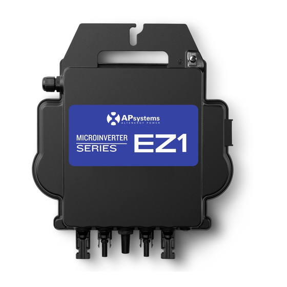
3. APsystems Microinverter EZ1 series Introduction Key Product Feature: One microinverter connects to two modules with independent MPPT Max output power reaching 600VA or 799VA for different models High Input current to adapter to large modules Maximum reliability, IP67 ... -
Page 9: Apsystems Microinverter System Installation
Allow a minimum of 1.5 cm (3/4’’) below and above the casing of the microinverter to allow proper air flow. The racking must be properly grounded as per local electrical code. 4.2.3 Step 3 - Connect APsystems Microinverters to the PV Modules Figure 3... -
Page 10: Step 4 - Connect The Apsystems Microinverter To Eu Power Cord
Make sure to not split positive and negative DC cables into two different input channels: microinverter will become damaged and warranty will not apply. 4.2.4 Step 4 - Connect the APsystems microinverter to EU power cord Insert the microinverter AC connector into the power cord connector. -
Page 11: Install And Use Ap Easypower
Remote Mode: Login account, users can realize remote monitoring and control of the device. In the absence of Wi-Fi, users can monitor and control the device in direct connection mode. Figure 7 APsystems Microinverter EZ1 series User manual... -
Page 12: Monitor & Control
By pressing “ alarm icon ” to check the alarm information if the device status is alarm. By pressing “ setting icon ” to set the device. The setting page is shown below. For Connection and monitoring operation mode, please refer to the AP EasyPower User Manual. APsystems Microinverter EZ1 series User manual... -
Page 13: Troubleshooting
APsystems Technical Support. 6.2 Trouble Shooting Guide Professional Users can also refer to our Troubleshooting Guide (https://emea.apsystems.com/resources/library/, section libraries)for more in depth guidelines on how to troubleshoot and fix PV installations powered by APsystems microinverters. 6.3 APsystems Technical Support The APsystems local Technical Support team is available to support professional installers in becoming familiar with our products and to troubleshoot installations when needed. -
Page 14: Replace A Microinverter
7. Replace a microinverter Follow the procedure to replace a failed APsystems Microinverter A. Disconnect the APsystems Microinverter from the PV Module, in the order shown below: 1. Disconnect the inverter from grid 2. Disconnect the PV module DC wire connectors from the microinverter. -
Page 15: Technical Data
①. Be sure to verify that the voltage and current specifications of your PV module are compatible with the range allowed on APsystems Microinverter. Please check the microinverter datasheet. ②. DC operating voltage range of the PV module must be within allowable input voltage range of the APsystems Microinverter. -
Page 16: Ez1 Series Microinverter Datasheet
Specifications subject to change without notice please ensure you are (2)The inverter may enter to power de-grade mode under poor ventilation and heat using the most recent update found at web : emea.APsystems.com dissipation installation environment. (3)The factory setting could be 600VA as default and raise to 800VA after intallation according to the regulation adjustment. -
Page 17: Ez1 Accessory
9. EZ1 Accessory 9.1 Dimensions Figure 9 APsystems Microinverter EZ1 series User manual... -
Page 18: Single Device
DC Male /Female Connector Cap DC Extension Cable AC T Connector (Optional) (Optional) (Optional) (Optional) (Optional) EZ1 EU Power Cord AC Connector(3C,17.5A,Female) DC Male /Female Connector Cap(MC4) 2m DC Extension Cable (MC4) AC T Connector(3C,17.5A) (1.5mm²,5m) APsystems Microinverter EZ1 series User manual...
Need help?
Do you have a question about the EZ1 Series and is the answer not in the manual?
Questions and answers