
Subscribe to Our Youtube Channel
Related Manuals for Mase Generators MPF 33-44


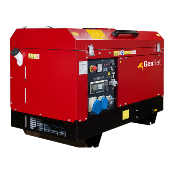
Summary of Contents for Mase Generators MPF 33-44
- Page 1 GRUPPO ELETTROGENO MANUALE DI USO E MANUTENZIONE GENSET USE AND MAINTENANCE MANUAL MPF 33 - 44 Rev.0 A.A. 23 - 05 - 11 cod.43054 Tipo modello N° matricola Codice...
-
Page 2: Table Of Contents
MPF 33-44 INDICE DEFINIZIONI USATE ..........4 Arresto ............22 Arresto d'emergenza ........22 INFORMAZIONI GENERALI....... 6 PROTEZIONI E SEGNALAZIONI ...... 22 Uso conforme ..........6 Rischi residui ........... 6 Protezione da cortocircuito e sovraccarico ..22 Simbologia sul gruppo elettrogeno ..... 7 Modulo protezione motore ...... - Page 3 47023 Cesena (FC) Italy Tel.+39-0547-354311 Fax.+39-0547-317555 Dati tecnici, informazioni,stesura dei testi ed allestimenti grafici: a cura dell’Ufficio Tecnico Mase Generators LA DITTA MASE GENERATORS SPA, SI RISERVA TUTTI I DIRITTI SUL PRESENTE MANUALE, NESSUNA RIPRODUZIONE TOTALE O PARZIALE E’ PERMESSA SENZA AUTORIZZAZIONE SCRITTA DELLA DITTA...
-
Page 4: Definizioni Usate
MPF 33-44 DEFINIZIONI USATE - I vocaboli usati sono quelli del linguaggio tecnico corrente e dove si è ritenuto necessario si riportano di seguito il significato - Gruppo elettrogeno E’ l’insieme di un motore a combustione interna a pistoni e un generatore di corrente alternata sincrono 2/4 poli autoeccitato, uniti tra loro per realizzare una centrale di autoproduzione di energia elettrica. - Page 5 MPF 33-44 - Connessione in cattivo stato Le parti attive non sono completamente ricoperte con un isolamento che possa essere rimosso solo mediante distruzione, le connessioni presentano una incertezza nel collegamento causata da un labile serraggio delle parti e da uno sviluppo di ossido fra le parti.
-
Page 6: Informazioni Generali
MPF 33-44 1 INFORMAZIONI GENERALI 1.1 U SO CONFORME Il gruppo elettrogeno è adatto a produrre autonomamente energia elettrica nei limiti di tensione e watt dichiarati dal costruttore. E’ vietato ogni altro uso al di fuori del campo di impiego già citato: la macchina è destinata ad un uso industriale. -
Page 7: Simbologia Sul Gruppo Elettrogeno
MPF 33-44 1.3 S IMBOLOGIA SUL GRUPPO ELETTROGENO cod. 41781 cod. 42119 cod. 42119 cod. 42351 STOP cod. 42346 cod. 42112 cod. 42348 cod. 42861 cod. 41777 cod. 41776 cod. 42118 cod. 42353 cod. 41776 cod. 42349 Cod.46223... -
Page 8: Significato Delle Etichette Di Sicurezza
MPF 33-44 1.4 Significato delle etichette di sicurezza • Queste etichette avvertono l’utente su eventuali pericoli che possono causare gravi lesioni. Leggere attentamente il significato e le precauzioni descritte nel presente manuale. • Se l’etichetta si stacca o diventa illeggibile, sostituirla con una nuova richiedendola ad un rivenditore autorizzato... - Page 9 MPF 33-44 Simboli di pericolo Significato - Pericolo di impigliamento e taglio: Presenza di parti rotanti, pulegge, cinghie, ventilatore. - Pericolo di ustioni: Superfici calde. - Pericolo di ustioni: Possibilità di espulsione acqua calda in pressione. Simboli di Obbligo Significato - Obbligo collegamento a terra del gruppo elettrogeno.
-
Page 10: Informazioni Generali Di Pericolo
MPF 33-44 1.5 I NFORMAZIONI GENERALI DI PERICOLO • Sia raccomanda la corretta conoscenza sia della modalità di arresto che di funzionamento di tutti i comandi. • Non lasciare che il gruppo elettrogeno venga utilizzato da personale non qualificato. • Anche se la macchina è protetta, evitare di sostare in prossimità del gruppo elettrogeno. -
Page 11: Pericolo Di Lesioni All'udito
MPF 33-44 1.5.3 P ’ ERICOLO DI LESIONI ALL UDITO • Non sostare per periodi prolungati senza cuffie di protezione, si possono avere riduzioni d’udito. Un esposizione prolungata al di sopra degli 85 dB(A) può provocare disturbi alla salute. Si consiglia in ogni caso l’utilizzo di appropriati sistemi di protezione (es. cuffie, tappi, ecc..). -
Page 12: Pericolo Causato Dall'avvio Del Motore
MPF 33-44 1.5.7 P ’ ERICOLO CAUSATO DALL AVVIO DEL MOTORE • Non lasciare parti smontate sul motore o nelle vicinanze, oppure attrezzi o quant'altro non facente parte dell'impianto. • Installare le protezioni necessarie per la sicurezza sulle parti di completamento impianto. -
Page 13: Documenti Di Riferimento
MPF 33-44 1.6 D 1.8 M OCUMENTI DI RIFERIMENTO ARCATURA Le istruzioni per l'uso fornite con ciascun gruppo La targa predisposta per i gruppi elettrogeni contiene elettrogeno sono costituite da una raccolta di documenti tutti i dati identificativi secondo quanto richiesto per la Marcatura CE, per i casi in cui è... -
Page 14: Caratteristiche Generali
MPF 33-44 2 CARATTERISTICHE GENERALI 12 Interruttore magnetotermico differenziale 13 Presa monofase CEE 16A 230V - 2P+T 14 Presa trifase CEE 16A 400V - 3P+T Il gruppo elettrogeno è stato progettato per l'impiego in campo 15 Presa trifase CEE 63A 400V - 3P+N+T industriale, utilizza motorizzazioni di alta affidabilità... -
Page 15: Tabella Caratteristiche Tecniche
MPF 33-44 2.4 T ABELLA CARATTERISTICHE TECNICHE MODELLO MPF 33 CARATTERISTICHE GENERALI L mm 1640 / 2403 DIMENSIONI W mm 770 / 1252 H mm 1076 / 1440 PESO 830 / 860 GRADO DI PROTEZIONE CLASSE D'ISOLAMENTO CAPACITA' SERBATOIO AUTONOMIA 3/4 DEL CARICO... -
Page 16: Emissione Sonora
MPF 33-44 2.5 E MISSIONE SONORA I valori riportati sono livelli di emissione e non necessa- te di lavoro, le altre sorgenti di rumore, quali il numero di riamente livelli operativi sicuri. Benché vi sia una corre- macchine e altri processi adiacenti, e la durata del lazione tra livelli di emissione e di esposizione, questa tempo di esposizione al rumore di un operatore. -
Page 17: Installazione
MPF 33-44 3 INSTALLAZIONE 3.1 C 3.3.1 T RITERI GENERALI D INSTALLAZIONE UBAZIONE DI SCARICO L’installazione di uno o più Gruppi elettrogeni deve Le tubazioni dovranno portare l’uscita del gas in zona dove essere progettata da tecnici specializzati ed abilitati alla non rechi danno o fastidio, lontano da porte, finestre o progettazione di questo tipo di impianti. -
Page 18: Collegamenti Elettrici
MPF 33-44 3.6 C OLLEGAMENTI ELETTRICI Non manomettere le protezioni attive, termici, L'esecuzione del collegamento elettrico, dovrà essere magnetotermici differenziali. eseguito esclusivamente da un installatore tecnico spe- • In caso di anomalie, non rimuovere il pannello per cializzato, seguendo le norme EN 60 204.1 (IEC 204.01). -
Page 19: Installazione All'esterno
MPF 33-44 3.7 I ’ NSTALLAZIONE ALL ESTERNO Per gruppi installati all’esterno si consiglia una posizione tale da permettere la massima protezione da agenti atmosferici, polvere, ecc. E' da evitare l’esposizione diretta ai raggi solari che provocano un riscaldamento anormale del complesso. -
Page 20: Installazione All'interno
MPF 33-44 3.8 I ’ NSTALLAZIONE ALL INTERNO Per una corretta installazione del gruppo in locale chiuso devono essere rispettate le regole di installazione elencate sotto: - Il locale deve essere adeguatamente dimensionato in modo da permettere il regolare funzionamento del gruppo nonché... -
Page 21: Utilizzo Del Generatore
MPF 33-44 4 UTILIZZO DEL GENERATORE 4.1 C ONTROLLI PRELIMINARI - Il rifornimento di carburante va eseguito sempre a motore spento e con selettore a chiave in posizione "0" Prima di iniziare qualsiasi procedura di avviamento è (STOP). estremamente importante "familiarizzare" con il gruppo - Non fumare e non usare fiamme libere durante l'ope- elettrogeno e i suoi comandi. -
Page 22: Utilizzo Del Gruppo Elettrogeno
MPF 33-44 4.7 A ’ RRESTO D EMERGENZA Per l’arresto di emergenza del gruppo in moto, agire sul “Pulsante Arresto di Emergenza” a fungo. Eliminate le cause che hanno determinato la necessità di un arresto di emergenza, per tornare in condizioni operative, occorre sbloccare il pulsante di arresto di emergenza. -
Page 23: Modulo Protezione Motore
MPF 33-44 5.2 M ODULO PROTEZIONE MOTORE Nel quadro elettrico è inserito un modulo di protezione motore per la protezione automatica del motore in caso si verifichi, durante il funzionamento normale, uno degli incon- venienti elencati di seguito. Preriscaldo "GLOW PLUG"... -
Page 24: Manutenzione
MPF 33-44 6 MANUTENZIONE 6.1 P REMESSA - Non disperdere nell'ambiente l'olio esausto in quanto prodotto inquinante. Qualsiasi intervento di manutenzione - Consegnare l'olio lubrificante esausto presso gli al gruppo elettrogeno va effettuato a motore spento, appositi Centri di Raccolta incaricati dello dopo averlo lasciato raffreddare a sufficienza. -
Page 25: Disareazione Impianto
MPF 33-44 6.4.1 D 6.5.1 D ISAREAZIONE IMPIANTO ISPOSITIVO DI SCARICO DELLA POLVERE La presenza di bolle d’aria, all’interno dell’impianto di alimen- - Svuotare il dispositivo di scarico della polvere (rif.4) tazione, è la causa del funzionamento irregolare del motore schiacciando con le dita nel senso delle due frecce i o l’incapacità... -
Page 26: Controllo Batteria
MPF 33-44 6.7 C ONTROLLO BATTERIA 6.9 T ABELLA INTERVENTI PROGRAMMATI La batteria (rif.1) necessita esclusivamente di un con- trollo periodico del livello dell'elettrolito e per un eventuale Controlli eseguibili sia dall'officina autorizzata che dal- rabbocco utilizzare solo acqua distillata. -
Page 27: Anomalie, Cause Rimedi
MPF 33-44 7 ANOMALIE, CAUSE RIMEDI Il gruppo elettrogeno, all'avviamento, non parte ed il motorino di avviamento non da alcun segnale. • Controllare che non sia intervenuto l'interruttore termico posto sul gruppo avviamento. Eseguire controllo collegamento batteria. Il motorino di avviamento gira ma il motore principale non si avvia. -
Page 28: Trasporto, Stoccaggio, Sollevamentoe Movimentazione
MPF 33-44 8 TRASPORTO, STOCCAGGIO, SOLLEVAMENTO E MOVIMENTAZIONE 8.1 T RASPORTO STOCCAGGIO Imballo: Viene fornito direttamente dalla ditta mase Il peso totale del gruppo elettrogeno imballato si trova al paragrafo 2.4 “Tabella caratteristiche tecniche”. E’ assolutamente vietato disperdere nell’ ambiente gli imballi. -
Page 29: Versione Con Carrello (Traino Lento)
MPF 33-44 8.3 V ERSIONE CON CARRELLO TRAINO LENTO È disponibile un carrello, completo di ruote e timone mobile per traino lento per la movimentazione. Su terreno in pendenza, al fine di evitare la marcia spontanea della macchina, utilizzare sempre tappi antirotolamento su ambedue le ruote (rif.1) . -
Page 30: Garanzia, Responsabilita
MPF 33-44 9 GARANZIA, RESPONSABILITA’ 9.1 G ARANZIA mase • I Gruppi elettrogeni , e tutti i suoi componenti sono garantiti privi di difetti, e sono coperti da garanzia per il periodo di 2 anni a partire dalla data di installazione. -
Page 31: Schema Elettrico
MPF 33 - 44 11 SCHEMI ELETTRICI 11.1 S CHEMA ELETTRICO Cod.48144 - 31... - Page 32 MPF 33-44 INDEX DEFINITIONS USED ..........4 USING THE GENERATOR ......21 GENERAL INFORMATIONS ......6 Preliminary checks ........21 Conform use ........... 6 Refuelling............21 Residual risks ..........6 Battery ............21 Symbols on the generator group ..... 7 Starting ............
- Page 33 Generators began as a company producing 500 Watt, light and compact portable generators. These generators made the Mase Generators name well known throughout the world. Mase Generators is a leader in high quality, reliable products, and innovative research performed by Research and Development Department.
- Page 34 MPF 33-44 DEFINITIONS USED - The terms used are current technical terms, and where considered necessary the meaning is described below - Generator An assembly of an internal combustion piston engine and an alternate current, synchronous, 2-4 pole, self-excited generator, joined together to create a station for self-production of electrical energy.
- Page 35 MPF 33-44 - Connection in bad state The live parts are not fully covered with insulation removable by destruction only, the connections are not secure because of unstable tightening of the parts and a development of oxide between the parts.
- Page 36 MPF 33-44 1 GENERAL INFORMATIONS 1.1 C ONFORM USE The generator is suitable for independent production of electrical energy within the voltage and wattage limits declared by the manufacturer. Any other use outside the already stated field of use is prohibited: the generator is intended for industrial use.
- Page 37 MPF 33-44 1.3 S YMBOLS ON THE GENERATOR GROUP cod. 41781 cod. 42119 cod. 42119 cod. 42351 STOP cod. 42346 cod. 42112 cod. 42348 cod. 42861 cod. 41777 cod. 41776 cod. 42118 cod. 42353 cod. 41776 cod. 42349 Cod.46223...
- Page 38 MPF 33-44 1.4 P OSITION OF SAFETY LABELS • These labels warn the user of any danger which may cause serious injury. Carefully read the meaning and the precautions described in this manual. • If the label detaches or becomes illegible, replace it with a new one which can be requested from an authorised mase dealer.
- Page 39 MPF 33-44 Danger Symbols Meaning - Danger of entanglement and cutting: Presence of rotating parts, pulleys, belts and fan. - Danger of burns: Hot surfaces. - Danger of burns: Possibility of pressurised hot water expulsion. Obligation Symbols Meaning - Obligation to connect the generator to earth.
- Page 40 MPF 33-44 1.5 G ENERAL DANGER INFORMATIONS • It is recommended to learn how to stop and operate all the controls. • Do not allow unqualified personnel to use the generator. • Even though the generator is protected, do not stand near it.
- Page 41 MPF 33-44 1.5.3 D ANGER OF HARM TO HEARING • Do not stand near the generator for long periods without protective earmuffs since hearing may be reduced. Prolonged exposure to noise above 85 dB(A) may cause health disorders. It is in any case recommended to use appropriate protection systems (e.g.
- Page 42 MPF 33-44 1.5.7 D ANGER CAUSED BY THE ENGINE STARTING • Do not leave disassembled parts, tools or anything else not forming part of the system on or near the engine. • Install the protections necessary for safety on the parts completing the system.
- Page 43 MPF 33-44 1.6 R 1.8 M EFERENCE DOCUMENTS ARKING The instructions for use provided with each generator are The generator identification plate carries all the made up of a collection of documents of which this manual identification data in accordance with the provisions for represents the General Part.
- Page 44 MPF 33-44 13 - Single-phase outlet, EC 16A 230V - 2P+GND 2 GENERAL CHARACTERISTICS 14 - Three-phase outlet, EC 16A 400V - 3P+GND 15 - Three-phase outlet, EC 63A 400V - 3P+N+GND The generators have been designed for use in the industrial field, using highly reliable 1500 rpm water-cooled diesel engines.
- Page 45 MPF 33-44 2.4 T ABLE OF TECHNICAL CHARACTERISTICS MODEL MPF 33 GENERAL CHARACTERISTICS L mm 1640 / 2403 DIMENSION W mm 770 / 1252 H mm 1076 / 1440 WEIGHT 830 / 860 DEGREE OF PROTECTION CLASS OF ISOLATION TANK CAPACITY...
- Page 46 MPF 33-44 2.5 N of the workforce are the characteristics of the workplace, OISE EMISSION other sources of noise, such as the number of machines The values listed are emission levels and not necessarily and other adjacent processes, and the time an operator is safe operating levels.
- Page 47 MPF 33-44 3 INSTALLATION 3.3.1 E XHAUST PIPE 3.1 G ENERAL INSTALLATION CRITERIA The exhaust pipe must convey the exhaust gas to a zone The installation of one or more Generating Sets must be where it will not cause damage or harm, and away from designed by specialised engineers qualified for the doors, windows and air intakes.
- Page 48 MPF 33-44 3.6 E LECTRICAL CONNECTION Do not tamper with the active protections, thermal The electrical connection must be carried out exclusively by switches and differential magnetothermal switches. a specialised technician according to EN 60 204.1 (IEC • In the event of malfunctioning, do not remove the 204.01) regulations...
- Page 49 MPF 33-44 3.7 O UTDOOR INSTALLATION For units in outdoor installations, it is advisable to ensure a position that provides maximum protection against atmospheric agents, powder, etc. Avoid direct exposure to sunlight that would otherwise cause abnormal heating of the system.
- Page 50 MPF 33-44 3.8 I NDOOR INSTALLATION Correct indoor installation of the system must observe the following installation requirements: The site must be adequately dimensioned in order to allow correct operation of the group as well as easy access for routine maintenance operations and eventual repairs. The figure shows the minimum recommended dimensions for clearance around the system and the height of the site.
- Page 51 MPF 33-44 4 USING THE GENERATOR 4.1 P RELIMINARY CHECKS - Refuelling must be carried out with the generator off Before beginning with any starting procedure, it is and the key selector in position "0" (STOP) extremely important to become «familiar» with the - Do not smoke and do not use open flames during generator and its controls.
- Page 52 MPF 33-44 4.7 E MERGENCY STOP For an emergency stop of the generator press the mushroom-head emergency stop button. Having removed the causes that determined the need for an emergency stop, release the emergency stop button in order to return to the operating conditions.
- Page 53 MPF 33-44 5.2 E NGINE ROTECTION ODULE An engine protection module is incorporated in the electric panel for automatic engine protection in the event that one of the problems listed below occur during operation. Preheating “GLOW PLUG” During the winter periods, when the environment tempe- rature is lower than 5°C, we recommend to perform a...
- Page 54 MPF 33-44 6 MAINTENANCE 6.1 P REAMBLE - Dispose of the used oil in an appropriate manner, since it is a polluting product. - Take the used engine oil to special collection Any maintenance operation on the generator must be centres for disposal.
- Page 55 MPF 33-44 6.4.1 S 6.5.1 D YSTEM BLEEDING UST EXHAUST DEVICE The presence of air bubbles in the fuel system is the - To empty the dust exhaust device (rif.4) pressing the cause of irregular functioning of the engine or the incapacity two lips with the fingers in the sense of the arrows.
- Page 56 MPF 33-44 6.7 B 6.9 S ATTERY CHECK CHEDULED MAINTENANCE TABLE The battery (rif.1) only needs to be checked periodically for The check indicated in this section can be carried out either electrolyte level and, if necessary, topped up with distilled by the workshop or by machine user.
- Page 57 MPF 33-44 7 ANOMALIES, CAUSES AND REMEDIES On starting, the generator does not run and the starter motor does not emit any signal. • Check that the thermal switch located on the start unit has not tripped. Check battery connection.
- Page 58 MPF 33-44 8 TRANSPORT, STORAGE, LIFTING AND HANDLING 8.1 T RANSPORT AND STORAGE mase Packaging: Supplied directly by The total weight of the packed generator is given in Paragraph 2.4 “Table of technical characteristics”. It is strictly prohibited to pollute the environment with the packaging Transport: During transport the generator (with or without packaging) must be protected against atmospheric agents, it must not be turned upside down and must be protected against knocks.
- Page 59 MPF 33-44 8.3 V ERSION WITH SLOW DRAWN TRAILER A trailer complete with wheels and mobile drawbar is available for movement. In order prevent the machine from rolling on sloping terrain, always use anti-rolling caps on both wheels (ref.1) .
- Page 60 MPF 33-44 9 GUARANTEE AND RESPONSIBILITY 9.1 G UARANTEE mase • The generators and all their components are guaranteed free of defects and are covered by the guarantee for a period of 2 year from the date of installation. • Not covered by the guarantee are: failed observance of the installation regulations, damage caused by natural...
- Page 61 MPF 33 - 44 11 WIRING DIAGRAMS 11.1 W IRING DIAGRAM Cod.48144 - 31...
- Page 62 Mase Generators S.p.a. • Via Tortona, 345 • 47522 Cesena (FC) ITALY • Tel. (+39) 0547.35.43.11 Fax (+39) 0547.31.75.55 • www.masegenerators.com • e-mail mase@masegenerators.com...
Need help?
Do you have a question about the MPF 33-44 and is the answer not in the manual?
Questions and answers