
Subscribe to Our Youtube Channel
Related Manuals for PIETRO FIORENTINI Staflux 187 H2


Summary of Contents for PIETRO FIORENTINI Staflux 187 H2
- Page 1 Staflux 187 H2 High pressure regulator Revision 00 - Edition 05/2022 USE, MAINTENANCE AND WARNING MANUAL...
- Page 2 HIGH PRESSURE REGULATOR INTRODUCTION REV. 00 Use, maintenance and warning manual...
-
Page 3: Introduction
It is of particular importance that the personnel responsible for the equipment be trained in its use, maintenance and ap- plication of the safety instructions and procedures indicated in this manual. Revision: 00 COPYRIGHT 2022 © PIETRO FIORENTINI S.P.A. HIGH PRESSURE REGULATOR INTRODUCTION REV. 00... - Page 4 HIGH PRESSURE REGULATOR INTRODUCTION REV. 00 Use, maintenance and warning manual...
-
Page 5: Revision History
1.1 - REVISION HISTORY Revision Date Revision contents index 05/2022 Tab. 1.1. HIGH PRESSURE REGULATOR INTRODUCTION REV. 00 Use, maintenance and warning manual... -
Page 6: Table Of Contents
CONTENTS 1 - INTRODUCTION ........................3 1.1 - REVISION HISTORY ..........................5 2 - GENERAL INFORMATION ....................11 2.1 - MANUFACTURER IDENTIFICATION ......................11 2.2 - IDENTIFICATION OF THE PRODUCT ...................... 11 2.3 - REGULATORY FRAMEWORK ......................... 11 2.4 - WARRANTY ............................11 2.5 - ADDRESSEES, SUPPLY AND STORAGE OF THE MANUAL .............. - Page 7 5.1 - SPECIFIC WARNINGS FOR TRANSPORT AND HANDLING ..............35 5.1.1 - PACKAGING AND FASTENERS USED FOR TRANSPORT ..............36 5.2 - PHYSICAL CHARACTERISTICS OF THE EQUIPMENT ................38 5.2.1 - STAFLUX 187 H2 ..........................38 5.3 - EQUIPMENT ANCHORING AND LIFTING METHOD................39 5.3.1 - FORKLIFT HANDLING METHOD ......................40 5.3.2 - CRANE HANDLING METHOD .......................42...
- Page 8 9.4.1 - TIGHTENING TORQUES STAFLUX 187 H2 ...................74 9.4.2 - REPLACING ELEMENTS SUBJECT TO WEAR AND ABRASION............77 9.4.3 - REGULATOR STAFLUX 187 H2 DN 1” ....................78 9.4.4 - MAINTENANCE PROCEDURE FOR THE PRESSURE GAUGE VALVE ...........82 9.4.5 - MAINTENANCE PROCEDURE FOR VS/FI SAFETY VALVE ..............84 10 - TROUBLESHOOTING......................
- Page 9 11 - UNINSTALLATION AND DISPOSAL ................. 91 11.1 - GENERAL SAFETY WARNINGS ......................91 11.2 - QUALIFICATION OF THE APPOINTED OPERATORS ................91 11.3 - UNINSTALLATION ........................... 91 11.4 - INFORMATION REQUIRED IN CASE OF RE-INSTALLATION ..............91 11.5 - DISPOSAL INFORMATION ........................92 12 - RECOMMENDED SPARE PARTS ..................
- Page 10 HIGH PRESSURE REGULATOR INTRODUCTION REV. 00 Use, maintenance and warning manual...
-
Page 11: General Information
PIETRO FIORENTINI S.P.A. with registered offices in Arcugnano (Italy) - Via E. Fermi, 8/10, declares under its sole respon- sibility that the equipment of the STAFLUX 187 H2 series described in this manual is designed, manufactured, tested and checked in compliance with the requirements of EN 334 standard on gas pressure regulators. -
Page 12: Addressees, Supply And Storage Of The Manual
Keep the manual near the equipment, in an accessible place known by all qualified technicians involved in using and running it. PIETRO FIORENTINI S.p.A. shall not be held liable for any damage to people, animals and property caused by failure to adhere to the warnings and operating procedures described in this manual. -
Page 13: Symbols Used In The Manual
2.6 - SYMBOLS USED IN THE MANUAL Symbol Definition Symbol used to identify important warnings for the safety of the operator and/or equipment. Symbol used to identify information of particular importance in the manual. The information may also concern the safety of the personnel involved in using the equipment. Referring to the instruction manual/booklet is mandatory. -
Page 14: Nameplates Applied
Removing nameplates and/or replacing them with other plates is strictly not allowed. Should the plates be unintentionally damaged or removed, the customer must notify PIETRO FIORENTINI S.p.A. The equipment and its accessories are provided with nameplates (from Id.1 to Id.8). -
Page 15: Glossary For Nameplates
2.7.1 - GLOSSARY FOR NAMEPLATES The terms and abbreviations used on the nameplates are described below: Term Description Accuracy class. Accuracy class of pressure boosting slam-shut valves. AG max “OPSO” (Over pressure shut off). Accuracy class of safety devices for pressure drop. AG min ”UPSO”(Under pressure shut off). - Page 16 Term Description Full setpoint range as a result of triggering caused by pressure decrease of the pressure switch Wdsu incorporated in the slam-shut valve. This range can be obtained by adjusting but not replacing the components. Tab. 2.6. HIGH PRESSURE REGULATOR GENERAL INFORMATION REV.
-
Page 17: Glossary Of Measurement Units
2.8 - GLOSSARY OF MEASUREMENT UNITS Type of measurement Unit of measurement Description Stm³/h Standard cubic metres per hour Volumetric flow rate Scfh Standard cubic feet per hour Unit of measurement in the CGS system Pounds per square inch Pressure “wc water column inch Pascal... -
Page 18: Qualified Professional Figures
2.9 - QUALIFIED PROFESSIONAL FIGURES Qualified operators in charge of using and managing the equipment throughout its technical service life: Professional figure Definition Qualified technician able to: • perform preventive/corrective maintenance operations on all mechanical parts of the Maintenance equipment subject to maintenance or repair; mechanical •... -
Page 19: Safety
3 - SAFETY 3.1 - GENERAL SAFETY INSTRUCTIONS WARNING! The equipment described in this manual is: • a device subjected to pressure in pressurised systems; • normally installed in systems carrying flammable gases (for example: natural gas or hydrogen). WARNING! If the gas used is a combustible gas, the installation area of the equipment is defined as a "dangerous area"... -
Page 20: Personal Protective Equipment
3.2 - PERSONAL PROTECTIVE EQUIPMENT Table 3.9 shows the personal protective equipment (PPE) and its description. An obligation is associated with each sym- bol. Personal protective equipment means any equipment intended to be worn by the worker in order to protect them against one or several risks that are likely to threaten their safety or health during work. -
Page 21: Residual Risks
3.3 - RESIDUAL RISKS In accordance with the requirements of PED 2014/68/EU, point 1.2 of Annex I, below is an assessment of the risks as- sociated with the equipment and an indication of the principles adopted for their prevention, according to the following classification: a) Elimination and/or reduction of the risk. - Page 22 3.3.1 - TABLE SHOWING RESIDUAL RISKS DUE TO PRESSURE Effect and Risk and Hazard Event and Cause Solution and Prevention Consequence a. Handling and installation with appropri- Pressurised gas • Deformation; ate devices to avoid localised stress. leakage. • Violent impact; •...
- Page 23 Effect and Risk and Hazard Event and Cause Solution and Prevention Consequence Pressurised • Deformation; gas leakage. a. With the exclusion of what is set out in • Cracking and slot Projection of • External loads bear- the project, the user must verify that no formation;...
-
Page 24: Table Of Residual Risks For Potentially Explosive Atmospheres
3.3.2 - TABLE OF RESIDUAL RISKS FOR POTENTIALLY EXPLOSIVE ATMOSPHERES Table 3.11 shows the conditions that can lead to the generation of a potentially explosive atmosphere. The table is valid for use with hydrogen with a density of no more than 0.0695; for different densities, the installation and environmental conditions must also be evaluated. - Page 25 Potentially Management measures Operating explosive Regulatory references included in the instructions conditions atmosphere for use and warning This event must be considered as a rare malfunction. Breakage of the All atmospheric pressure chambers The instructions for use indicate control head delimited on at least one side by a the need to meet the requirements diaphragm...
-
Page 26: Obligations And Prohibitions
3.4 - OBLIGATIONS AND PROHIBITIONS The following is a list of obligations and prohibitions to be observed for the safety of the operator. It is obligatory to: • carefully read and understand the instructions for use and warning; • check whether the downstream equipment is suitably sized according to the performance required of the regulator in the actual operating condition;... -
Page 27: Safety Pictograms
Depending on the operating conditions, use and configuration required, the equipment may generate noise other than that permitted by current legislation in the country of installation. For the value of the noise generated by the equipment and further information, contact PIETRO FIORENTINI S.p.A. ATTENTION! - Page 28 HIGH PRESSURE REGULATOR SAFETY REV. 00 Use, maintenance and warning manual...
-
Page 29: Description And Operation
4 - DESCRIPTION AND OPERATION 4.1 - GENERAL DESCRIPTION The equipment STAFLUX 187 H2 is a pressure regulator for high pressure which reduces the inlet gas pressure, keeping the downstream value stable even when the following varies: • inlet pressure value;... -
Page 30: Regulator Reaction Modes
4.1.1 - REGULATOR REACTION MODES The STAFLUX 187 H2 equipment is a direct-acting regulator with a “fail open” reaction (on-opening reaction), that is, it opens in the event of: • breakage of the main diaphragm • lack of power supply. - Page 31 Operating conditions Operating consequences Concluding outcome Downstream pressure (Pd) • Imbalance of forces Opening of the plug (1) until the equi- decreases due to an increase in • Decrease of pressure in the sub-dia- librium condition is restored the required flow rate phragm chamber (3) Downstream pressure (Pd) •...
-
Page 32: Intended Use
If no written approval is provided, use shall be considered improper. In the event of “improper use”, PIETRO FIORENTINI S.p.A. shall not be held liable for any damage caused to people or property, and any type of warranty on the equipment shall be deemed void. -
Page 33: Technical Features/Performance
The STAFLUX 187 H2 equipment is a medium and high pressure regulator. STAFLUX 187 H2 is a “top entry” type regulator that can be easily serviced and equipped with on-site accessories. The regulation system is balanced and guarantees a stable outlet pressure even when the inlet pressure varies. -
Page 34: Possible Configurations
4.5 - POSSIBLE CONFIGURATIONS NOTE! No configurations other than the standard configuration are envisaged for the equipment referred to in this document. HIGH PRESSURE REGULATOR DESCRIPTION AND OPERATION REV. 00 Use, maintenance and warning manual... -
Page 35: Transport And Handling
5 - TRANSPORT AND HANDLING 5.1 - SPECIFIC WARNINGS FOR TRANSPORT AND HANDLING NOTE! Transport and handling must be carried out by personnel: • qualified (specially trained); • who are familiar with accident prevention and workplace safety regulations; • authorised to use lifting equipment; •... -
Page 36: Packaging And Fasteners Used For Transport
PIETRO FIORENTINI S.p.A.. NOTE! PIETRO FIORENTINI S.p.A. shall not be liable for any damage to people or property caused by accidents due to failure to comply with the instructions provided in this manual. Below is a list of the types of packaging used: Ref. - Page 37 HIGH PRESSURE REGULATOR TRANSPORT AND HANDLING REV. 00 Use, maintenance and warning manual...
-
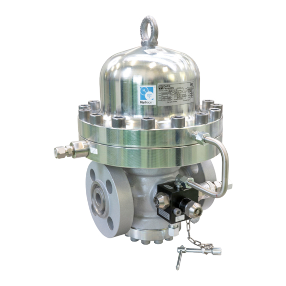
Page 38: Physical Characteristics Of The Equipment
5.2 - PHYSICAL CHARACTERISTICS OF THE EQUIPMENT 5.2.1 - STAFLUX 187 H2 Fig. 5.3. STAFLUX 187 H2 physical characteristics STAFLUX 187 H2 overall dimensions - CONNECTION WITH FLANGES Nominal diameter [mm] Size [inches] 1” 73.5 Tab. 5.19. Weight [kgf] DN 1”... -
Page 39: Equipment Anchoring And Lifting Method
5.3 - EQUIPMENT ANCHORING AND LIFTING METHOD HAZARD! Before moving the equipment, make sure that the capacity of the lifting equipment is suitable for the load. WARNING! Unloading, transport and handling activities must be carried out by operators qualified and specially trained: •... -
Page 40: Forklift Handling Method
5.3.1 - FORKLIFT HANDLING METHOD HAZARD! Prohibitions: • Do not transit under suspended loads; • Do not move the load overhead of the personnel operating in the site/plant area. WARNING! • Do not use forklifts to carry people; • Do not use forklifts to lift people. NOTE! Packaging must always be handled in a vertical position Proceed as follows:... - Page 41 Step Action Image Sollevare lentamente il carico di qualche decina di centimetri e veri carne la stabilità facendo attenzio- Inclinare il montante all’indietro (verso il posto guida) per avvantaggiare il momento ribaltante e Adeguare la velocità d ne che il baricentro del carico sia posizionato al centro delle forche di sollevamento. garantire una maggiore stabilità...
-
Page 42: Crane Handling Method
5.3.2 - CRANE HANDLING METHOD WARNING! CE-marked chains, ropes and eyebolts must be used. Do not use chains connected to each other by bolts. Always check that: • the safety catch of the hook returns to the initial position; • the ropes are in excellent condition and have an adequate section. -
Page 43: Packaging Removal
• do not install the equipment; • contact PIETRO FIORENTINI S.p.A. and specify the details provided on the equipment nameplate. 5.4.1 - PACKAGING DISPOSAL NOTE! Sort the various materials making up the packaging and dispose of them in compliance with the regula- tions in force in the country of installation. -
Page 44: Storage And Environmental Conditions
To replace the rubber parts of the equipment, please refer to chapter 9 “Maintenance and functional checks”. NOTE! PIETRO FIORENTINI S.p.A. recommends checking the condition of rubber parts in case of downtime or storage of more than 3 years. HIGH PRESSURE REGULATOR TRANSPORT AND HANDLING REV. -
Page 45: Installation
6 - INSTALLATION 6.1 - INSTALLATION PRE-REQUISITES 6.1.1 - ENVIRONMENTAL CONDITIONS ALLOWED WARNING! To safely use the equipment, adhere to the environmental conditions allowed and to the data provided on the nameplate of the regulator and any accessories (refer to paragraph 2.7 “Nameplates applied”). The installation site must be suitable for the safe use of the equipment. -
Page 46: Checks Before Installation
6.1.2 - CHECKS BEFORE INSTALLATION The equipment does not require any further safety device upstream to be protected against any overpressure with respect to its PS admissible pressure when, for the upstream reduction station, the maximum incidental downstream pressure is: MIPd ≤... -
Page 47: Specific Safety Instructions For The Installation Step
6.2 - SPECIFIC SAFETY INSTRUCTIONS FOR THE INSTALLATION STEP WARNING! Before proceeding with installation, make sure that the upstream and downstream valves installed on the line are closed. WARNING! Installation may also take place in areas where there is a risk of explosion, and this implies that all neces- sary prevention and protection measures must be taken. -
Page 48: General Information On Connections
6.3 - GENERAL INFORMATION ON CONNECTIONS The equipment must be installed in the line with the arrow on the body pointing in the gas flow direction. For installation in line as well as in a square pattern, the following must be on hand: Pos. -
Page 49: Regulator Installation Positions
NOTE! When used in gas pressure reduction stations, the device must be installed at least according to the re- quirements of standards UNI EN 12186:2014 or UNI EN 12279:2007. Equipment vents must be ducted in accordance with UNI EN 12186:2014 or UNI EN 12279:2007 or the standards in force at the place of installation of the equipment. -
Page 50: Installation Procedures
6.5 - INSTALLATION PROCEDURES 6.5.1 - EQUIPMENT INSTALLATION PROCEDURE To install the equipment in line and in a square pattern, proceed as follows: Step Action Place the equipment in the section of the line designated for it. Place the gaskets between the line flange and the regulator flange. Insert the bolts into the appropriate holes of the connecting flanges. - Page 51 To calculate the flow rate, use the following formula: 1 − 0,002 = 345,92 V = gas velocity in m/sec Q = gas flow rate Stm³/h DN = nominal diameter of the regulator in mm Pd = regulator outlet pressure in barg NOTE! All on-site pneumatic connections must have pipes with a minimum internal diameter of 8 mm To prevent the sensing line pipes from collecting impurities and condensation, it is necessary that:...
-
Page 52: Post-Installation And Pre-Commissioning Checks
If there is a sensing line, provide equipment connections as shown below: • 1 and 2 to the discharge outlet of the control head of the monitor, if any; • 3 and 4 to the pilot sensing lines; • 5 and 6 to the sensing lines of the accelerator of the slam-shut device, if any. NOTE! If there is a multiple sensing line, it is not recommended to place shut-off valves on sensing lines. -
Page 53: Commissioning/Maintenance Equipment
7 - COMMISSIONING/MAINTENANCE EQUIPMENT 7.1 - LIST OF EQUIPMENT Commissioning/maintenance equipment • Mechanical maintenance technician; • Electrical maintenance technician; Operator qualification • Installer; • User’s technician. WARNING! The PPE listed in this table is related to the risk associated with the equipment. PPE required For the PPE required to protect against risks associated with the workplace, installation or operating conditions, please refer to:... - Page 54 Ref. Equipment type Image T-handle hex socket wrench Phillips screwdriver Slotted screwdriver O-ring extraction tool Circlip pliers Fiorentini special key Fiorentini special key Tab. 7.30. HIGH PRESSURE REGULATOR REV. 00 COMMISSIONING AND MAINTENANCE EQUIPMENT Use, maintenance and warning manual...
-
Page 55: Equipment Needed For The Different Configurations
Ref. Reference to the equipment indicated in tab. 7.48 Type Type (size) or code of the equipment Tab. 7.31. STAFLUX 187 H2 Equipment Ref. Type 1” 6 - 7 - 14 - 15 - 19 - 24 - 27 - 41 Ø... - Page 56 HIGH PRESSURE REGULATOR REV. 00 COMMISSIONING AND MAINTENANCE EQUIPMENT Use, maintenance and warning manual...
-
Page 57: Commissioning
8 - COMMISSIONING 8.1 - GENERAL WARNINGS 8.1.1 - SAFETY REQUIREMENTS FOR COMMISSIONING HAZARD! During commissioning the risks associated with any discharges to the atmosphere of flammable or nox- ious gases must be evaluated. HAZARD! In case of installation on hydrogen or natural gas distribution networks, one should consider the risk of explosive mixtures (gas/air) forming inside the piping, if the line is not subjected to inertisation. -
Page 58: Preliminary Procedures For Commissioning
8.2 - PRELIMINARY PROCEDURES FOR COMMISSIONING HAZARD! Before commissioning the equipment, it must be ensured that any source of potential explosion has been eliminated if there is such a danger. WARNING! Before commissioning, you need to make sure that the characteristics of the equipment are suitable for the conditions of use. -
Page 59: Proper Commissioning Check
8.3 - PROPER COMMISSIONING CHECK Completely sprinkle the equipment with a foaming solution in order to check the tightness of the regulator’s external sur- faces and of the connections made during installation (or equivalent control system). 8.4 - CALIBRATION OF ANY ACCESSORIES AVVISO! To properly calibrate the equipment and all the accessories, refer to the accuracy class indicated on the nameplate (see paragraph 2.8). -
Page 60: Commissioning The Regulator
8.5 - COMMISSIONING THE REGULATOR In the application consisting of two pressure adjusting lines, it is advisable to commission one line at a time, starting with the line with the lowest set point. The set point value is mentioned on the test certificate enclosed with each piece of equipment. Fig. - Page 61 Step Action Open the air vent valve (6). NOTE! Check the pressure by referring to the pressure gauge (5) located downstream. Open very slowly the inlet shut-off valve (V1). Adjust the setting value of the VS/FI relief valve by means of the pressure gauge valve (7). Close the air vent valve (6).
-
Page 62: Working Pressure Adjustment
8.5.1 - WORKING PRESSURE ADJUSTMENT 8.5.1.1 - OUTLET PRESSURE REGULATION VIA PRESSURE GAUGE VALVE The pressure gauge valve allows the pressure inside the equipment head to be charged or discharged. To adjust the downstream pressure of the regulator via the pressure gauge valve connect inlet pressure connection pipe with a external source of inert gas or compressed air for instrument. - Page 63 Step Action Turn the adjustment screws to increase or decrease the calibration pressure: • to increase the calibration pressure: open the screw until the desired setting is reached and close it again when the desired setting value is reached • to decrease the calibration pressure: open the screw until the desired setting is reached and close it again when the desired setting value is reached Tab.
-
Page 64: Calibration Procedure For The Vs/Fi Relief Valve
8.5.1.2 - CALIBRATION PROCEDURE FOR THE VS/FI RELIEF VALVE The pressure gauge valve allows the pressure inside the equipment head to be charged or discharged. To adjust the downstream pressure of the regulator via the pressure gauge valve connect inlet pressure connection pipe with a external source of inert gas or compressed air for instrument. - Page 65 Step Action Loosen the ring nuts (5, 11). Increase the pressure in the bell chamber in order to increase the downstream pressure (Pd) until the desired cut-in pressure of the VS/FI relief valve is reached. AVVISO! Check the pressure by referring to the pressure gauge (fig. 8.25 rif. 5) located downstream. If the valve: •...
- Page 66 HIGH PRESSURE REGULATOR COMMISSIONING REV. 00 Use, maintenance and warning manual...
-
Page 67: Maintenance And Functional Checks
WARNING! In case of doubt, do not perform any work. Contact PIETRO FIORENTINI S.p.A. for the necessary clarifica- tions. The management and/or use of the equipment includes interventions that are necessary as a result of normal use such as: •... - Page 68 Before beginning disassembly of the equipment, make sure that: • the spare parts and parts used in replacements have adequate requirements to ensure the original performance of the equipment. Use recommended original spare parts; • the operator has the necessary equipment (see chapter 7 “Equipment for commissioning/maintenance”). NOTE! The recommended spare parts are unambiguously identified with tags indicating: •...
-
Page 69: Periodically Checking And Inspecting The Equipment For Proper Operation
9.2 - PERIODICALLY CHECKING AND INSPECTING THE EQUIPMENT FOR PROPER OPERATION Periodic checks and inspections Operator qualification Mechanical maintenance technician WARNING! The PPE listed in this table is related to the risk associated with the equipment. PPE required For the PPE required to protect against risks associated with the workplace, installation or operating conditions, please refer to: •... -
Page 70: Routine Maintenance
9.3 - ROUTINE MAINTENANCE 9.3.1 - GENERAL SAFETY WARNINGS HAZARD! • Put the equipment in a safe condition (close the downstream and then the upstream shut-off valve, drain the equipment completely and lastly drain the line); • Ensure that the pressure upstream and downstream of the equipment is “0”. NOTE! Before installing new sealing elements (o-rings, diaphragm, etc.), they must be checked for integrity. -
Page 71: Replacement Frequency For Components Subject To Wear
9.3.2 - REPLACEMENT FREQUENCY FOR COMPONENTS SUBJECT TO WEAR NOTE! The following provisions shall apply to equipment components only. The non-metallic parts of the equipment concerned are divided into the following two categories: Preventive maintenance work Covers parts subject to wear and/or abrasion, where: •... - Page 72 Minimum Category Part description Evaluation criterion replacement frequency Shut-off valves Yearly Lubricating parts Other equipment Yearly Filter elements Filters needed Tab. 9.42. HIGH PRESSURE REGULATOR MAINTENANCE AND FUNCTIONAL CHECKS REV. 00 Use, maintenance and warning manual...
-
Page 73: Routine Maintenance Procedures
9.4 - ROUTINE MAINTENANCE PROCEDURES Routine maintenance Operator qualification Mechanical maintenance technician WARNING! The PPE listed in this table is related to the risk associated with the equipment. PPE required For the PPE required to protect against risks associated with the workplace, installation or operating conditions, please refer to: •... -
Page 74: Tightening Torques Staflux 187 H2
9.4.1 - TIGHTENING TORQUES STAFLUX 187 H2 Fig. 9.14. Tightening torques STAFLUX 187 H2 HIGH PRESSURE REGULATOR MAINTENANCE AND FUNCTIONAL CHECKS REV. 00 Use, maintenance and warning manual... - Page 75 STAFLUX 187 H2 DN 1” Pos. Description Torque (nm) Torque (ft - lb) Screw Screw Screw Tab. 9.44. HIGH PRESSURE REGULATOR MAINTENANCE AND FUNCTIONAL CHECKS REV. 00 Use, maintenance and warning manual...
- Page 76 HIGH PRESSURE REGULATOR MAINTENANCE AND FUNCTIONAL CHECKS REV. 00 Use, maintenance and warning manual...
-
Page 77: Replacing Elements Subject To Wear And Abrasion
9.4.2 - REPLACING ELEMENTS SUBJECT TO WEAR AND ABRASION 9.4.2.1 - INITIAL OPERATIONS ATTENTION! Before carrying out any work, it is important to ensure that the line on which the regulator is installed has been shut off upstream and downstream, and discharged. ATTENTION! During assembly, make sure to tighten the screws as per the tables (tightening torques), according to the size for which maintenance is being carried out. -
Page 78: Regulator Staflux 187 H2 Dn 1
9.4.3 - REGULATOR STAFLUX 187 H2 DN 1” 32.6 32.5 Fig. 9.16. Regulator STAFLUX 187 H2 DN 1” HIGH PRESSURE REGULATOR MAINTENANCE AND FUNCTIONAL CHECKS REV. 00 Use, maintenance and warning manual... - Page 79 Step Action Unscrew and remove the screws (26) from the lower flange (4). Remove the lower flange (4). Remove the guide O-ring (42) and replace it, taking care to lubricate it with synthetic grease. AVVISO! Before inserting the replacement guide ring, clean the retaining slots with a cleaning solution. Unscrew and remove the screws (27) from the cover (3).
- Page 80 32.6 32.5 Regulator STAFLUX 187 H2 DN 1” HIGH PRESSURE REGULATOR MAINTENANCE AND FUNCTIONAL CHECKS REV. 00 Use, maintenance and warning manual...
- Page 81 Step Action Put the gasket support (18) in place. While keeping the stem (12) still, insert and fix the nut (17). Put the stem guide (10) together with guide O-ring (40) back on the flange (2). Put the support (11) together with stem (12), nut (17), support gasket (18), gasket (16) and the guide O-rings (35, 36, 41, 38).
-
Page 82: Maintenance Procedure For The Pressure Gauge Valve
9.4.4 - MAINTENANCE PROCEDURE FOR THE PRESSURE GAUGE VALVE Fig. 9.17. Pressure gauge valve HIGH PRESSURE REGULATOR MAINTENANCE AND FUNCTIONAL CHECKS REV. 00 Use, maintenance and warning manual... - Page 83 Step Action Unscrew and remove the cap (2). Unscrew and remove the shaft (3) from the cap (2). Remove the guide O-ring (10) and replace it, taking care to lubricate it with synthetic grease. AVVISO! Before inserting the replacement guide ring, clean the retaining slots with a cleaning solution. Unscrew and remove the nut (4).
-
Page 84: Maintenance Procedure For Vs/Fi Safety Valve
9.4.5 - MAINTENANCE PROCEDURE FOR VS/FI RELIEF VALVE GAS INLET Fig. 9.18. VS/FI Relief valve HIGH PRESSURE REGULATOR MAINTENANCE AND FUNCTIONAL CHECKS REV. 00 Use, maintenance and warning manual... - Page 85 Step Action Loosen ring nuts (5, 11). Unscrew the adjustment cap (2). Remove the guide O-ring (14) and replace it, taking care to lubricate it with synthetic grease. AVVISO! Before inserting the replacement guide ring, clean the retaining slots with a cleaning solution. Remove the spacers (6, 7) together with the spring (9).
- Page 86 HIGH PRESSURE REGULATOR MAINTENANCE AND FUNCTIONAL CHECKS REV. 00 Use, maintenance and warning manual...
-
Page 87: Troubleshooting
• qualified and authorised to carry out activities related to the equipment. WARNING! PIETRO FIORENTINI S.p.A. shall not be held liable for any damage to people and property due to services: • other than those described; • performed according to methods other than those specified;... -
Page 88: Operator Qualification Specification
10.2 - OPERATOR QUALIFICATION SPECIFICATION Commissioning • Mechanical maintenance technician; • Electrical maintenance technician; Operator qualification • Installer; • Name of the user. WARNING! The PPE listed in this table is related to the risk associated with the equipment. PPE required For the PPE required to protect against risks associated with the workplace, installation or operating conditions, please refer to: •... -
Page 89: Troubleshooting Tables
10.4 - TROUBLESHOOTING TABLES NOTE! Refer to chapter 9 “Maintenance and functional checks” for the pictures of the STAFLUX 187 H2 regulator and its accessories. 10.4.1 - STAFLUX 187 H2 TROUBLESHOOTING Failure Appliance Possible causes Service Valve seat (11) damaged... - Page 90 HIGH PRESSURE REGULATOR TROUBLESHOOTING REV. 00 Use, maintenance and warning manual...
-
Page 91: Uninstallation And Disposal
11 - UNINSTALLATION AND DISPOSAL 11.1 - GENERAL SAFETY WARNINGS HAZARD! Make sure that there are no potentially explosive ignition sources in the work area set up to uninstall and/ or dispose of the equipment. WARNING! Before proceeding with uninstallation and disposal, make the equipment safe by disconnecting it from any power supply. -
Page 92: Disposal Information
11.5 - DISPOSAL INFORMATION NOTE! Bear in mind that the laws in force in the country of installation must be complied with. Illegal or improper disposal involves the application of the penalties provided for by the legislation in force in the country of installation. NOTE! Proper disposal prevents damage to humans and the environment and promotes the reuse of precious raw materials. -
Page 93: Recommended Spare Parts
If spare parts not marked are used, PIETRO FIORENTINI S.p.A. their declared performance cannot be guaranteed. It is recommended to use original spare parts PIETRO FIORENTINI S.p.A. PIETRO FIORENTINI S.p.A. shall not be held liable for any damage caused by using non-original parts. 12.2 - HOW TO REQUEST SPARE PARTS NOTE! For specific information, please refer to the sales network of PIETRO FIORENTINI S.p.A. - Page 94 HIGH PRESSURE REGULATOR RECOMMENDED SPARE PARTS REV. 00 Use, maintenance and warning manual...
-
Page 95: Calibration Tables
13 - CALIBRATION TABLES 13.1 - VS/FI RELIEF VALVE CALIBRATION TABLE 302/A Pos. Spring item code Spring colour Min. 2700713 Green 2700750 Black 18.5 2700985 Brown 2701182 Blue d = Wire Diameter (mm) Lo = Spring Length (mm) De = External Diameter (mm) Tab.
Need help?
Do you have a question about the Staflux 187 H2 and is the answer not in the manual?
Questions and answers