Sign In
Upload
Manuals
Brands
Texas Instruments Manuals
Control Unit
ADS5296
Texas Instruments ADS5296 Manuals
Manuals and User Guides for Texas Instruments ADS5296. We have
1
Texas Instruments ADS5296 manual available for free PDF download: User Manual
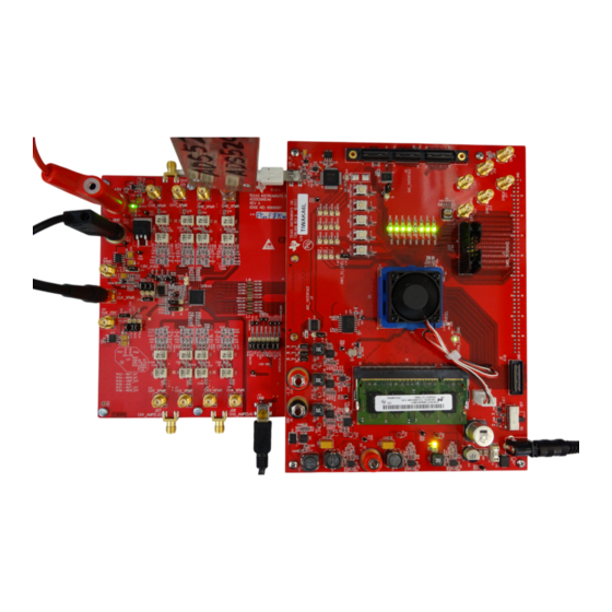
Texas Instruments ADS5296 User Manual (84 pages)
4-Channel 200-MSPS, and 8-Channel 80-MSPS, Analog-to-Digital Converter Evaluation Module
Brand:
Texas Instruments
| Category:
Control Unit
| Size: 14.73 MB
Table of Contents
Table of Contents
1
Quick View of Evaluation Setup
4
GUI Software Installation
5
TSW1400 EVM GUI Installation (High Speed Data Converter Pro (Hsdcpro))
5
ADS5296 EVM GUI Installation
11
ADS5296 GUI Install (D)
15
ADS5296 GUI Install (E)
16
ADS5296 GUI Install (F)
17
Hardware and EVM Setup for Testing ADS5296
18
External Connections
18
ADS5296 GUI Install (G)
18
ADS5296 EVM Header Configuration
19
TSW1400 and ADS5296 Setup
19
ADS5296 EVM Header Configuration
20
ADS5296 EVM 0-Ω Jumper Configuration
21
ADS5296 EVM Default Header Configuration
21
ADS5296 EVM Octal Non-Interleaving Mode Analog Input Smas
22
ADS5296 EVM Quad Interleaving Mode Analog Input Smas
23
Testing ADS5296 EVM
24
TSW1400 and ADS5296 GUI Setup
24
TSW1400 GUI Setup (A)
24
TSW1400 GUI Setup (B)
24
TSW1400 GUI Setup (C)
24
TSW1400 GUI Setup (D)
24
TSW1400 GUI Setup (E)
24
TSW1400 GUI Setup (F)
24
ADS5296 Plug-In GUI Setup (A)
27
ADS5296 Plug-In GUI Setup (B)
28
Capturing a RAMP Test Pattern
29
ADS5296 Plug-In GUI Setup (C)
29
ADS5296 GUI Setup for RAMP Test
30
Hsdcpro GUI Setup for RAMP Test
31
RAMP Capture
32
RAMP Capture by Channel
33
Capturing Sinusoidal Input in Octal Non-Interleaving Mode
34
Zoom on RAMP Capture
34
Jumper J35 and J38 Positions for Enabled XTAL (Default)
35
Jumper J35 and J38 Positions for Disabled XTAL
36
Octal Non-Interleaving Mode Hardware Setup
37
ADS5296 GUI Setup for Octal Non-Interleaving Mode
38
Hsdcpro GUI Setup for Octal Non-Interleaving Mode (B)
39
Capturing Sinusoidal Input in Quad Interleaving Mode
45
ADS5296 GUI in Detail
50
Read Me First Tab
52
Top Level Tab
53
Test Pattern Tab
57
PRBS Section Enabled
58
Digital Signal Processing Tab
59
TEST PATTERN MODES Section
59
Channel Averaging Info Button
60
Channel Filter Tab
61
INPUT/OUTPUT MAPPING with EN_INTERLEAVE
61
INPUT/OUTPUT MAPPING with EN_INTERLEAVE = 1
61
Dig_Filter
63
Channel 5 High Pass Filter Enabled
63
Channel 1 Digital Filter Enabled
64
Channel 1 Pre-Stored Digital Filter Enabled
64
Channel 1 Custom Digital Filter Enabled
65
Reset Channels on Channel Filter Tab
65
Save/Load Custom Filter Coeffs on Channel Filter Tab
66
View Filter Coeffs
66
ADS5296 EVM Schematics
67
ADS5296 Schematic, Sheet 1 of
67
ADS5296 Schematic, Sheet 2 of
68
ADS5296 Schematic, Sheet 3 of
69
ADS5296 Schematic, Sheet 4 of
70
ADS5296 Schematic, Sheet 5 of
71
ADS5296 Schematic, Sheet 6 of
72
ADS5296 Schematic, Sheet 7 of
73
ADS5296 Schematic, Sheet 8 of
74
ADS5296 Schematic, Sheet 9 of
75
ADS5296 EVM Bill of Materials
76
ADS5296 EVM Bill of Materials
77
ADS5296 EVM Layout
78
ADS5296 EVM Top Layer Assembly Drawing - Top View
78
ADS5296 EVM Bottom Layer Assembly Drawing - Bottom View
79
ADS5296 EVM Top Side
80
ADS5296 EVM Ground Plane
81
ADS5296 EVM Signal Plane
82
ADS5296 EVM Bottom Side
83
Advertisement
Advertisement
Related Products
Texas Instruments ADS54J64
Texas Instruments ADS5231 EVM
Texas Instruments ADS5232 EVM
Texas Instruments ADS5237 EVM
Texas Instruments ADS1131REF
Texas Instruments ADS7138-Q1
Texas Instruments ADS8353-Q1
Texas Instruments ADS8353Q1EVM-PDK
Texas Instruments ADS9227
Texas Instruments ADS9227EVM
Texas Instruments Categories
Motherboard
Control Unit
Microcontrollers
Computer Hardware
Calculator
More Texas Instruments Manuals
Login
Sign In
OR
Sign in with Facebook
Sign in with Google
Upload manual
Upload from disk
Upload from URL