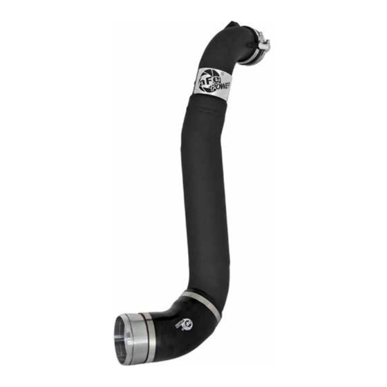
Summary of Contents for aFe Power 46-20299-B
- Page 1 FLOW engineering Instruction Manual P/N: 46-20299-B Make: Ford Model: F-150 Raptor Year: 2017-2020 Engine: V6-3.5L (tt) EcoBoost...
- Page 2 • Please read the entire instruction manual before proceeding. • Ensure all components listed are present. • If you are missing any of the components, call customer support at 951-493-7185. • Ensure you have all necessary tools before proceeding. • Do not attempt to work on your vehicle when the engine is hot. •...
- Page 3 aFepower.com Page 3...
- Page 4 REMOVAL Figure A Refer to Figure A for Steps 1-6 Step 1: Park vehicle on level ground and engage parking brake. Step 2: Remove intake Y-pipe by loosening the three clamps using a 7mm socket or nut driver and disconnecting the sensor. (Figure A). Step 3: Disconnect the vent tube by squeezing the retaining clip and pushing it through to release it, then gently pull it off the intercooler tube.
- Page 5 REMOVAL Figure B Refer to Figure B for Steps 7-12 Step 7: Under the vehicle you will need to remove the six bolts securing the skid plate to the truck. Step 8: Once the skid plate is removed disconnect the pressure relief valve tube on the driver side of the vehicle right above the intercooler tube connection by twisting it a ¼...
- Page 6 INSTALL Figure C Refer to Figure C for Steps 13-14 Step 13: Place the small silicone coupling over the small end of the aFe intercooler tube with one of the smaller supplied clamps and install the 1/8” NPT plug into the fitting. NOTE: Be sure to use thread sealant on the threads prior to instillation.
- Page 7 INSTALL Figure D Refer to Figure D for Steps 15-17 Step 15: Install the factory retaining clip into the groove on the outside of the supplied aluminum adaptor (Figure A). Step 16: Install the supplied O-ring into the groove on the inside the aluminum adaptor (Figure A). NOTE: Lube the O-rings for the adaptor and the sensor from Step 5 with a small amount of grease, prior to installation, to prevent the O-ring from tearing.
- Page 8 INSTALL Figure E Refer to Figure E for Steps 18-20 Step 18: Install the intercooler tube from the top of the vehicle. Step 19: Install the aluminum adaptor onto the intercooler and then onto the intercooler tube, be sure that the clip snaps all the way into the groove on the intercooler. Step 20: Up top, install the throttle body coupling onto the throttle body with the last clamp.
- Page 9 INSTALL Figure F Refer to Figure F for Steps 21-23 Step 21: Reinstall the relief valve tube from Step 8. Step 22: Ensure intercooler tube is not resting on any plastic or metal surfaces then tighten all clamps. Step 23: Reinstall factory skid plate. Page 9 aFepower.com...
- Page 10 Step 24: Up top, reconnect the vent tube onto the aFe intercooler tube and lock it with the retaining clip. Step 25: Reconnect the sensor from Step 4. Step 26: Reinstall intake y-pipe and the tighten clamps. Step 27: Reconnect the sensor in the intake tube. Install is now complete. Thank you for choosing aFe Power. Enjoy! Page 10...
- Page 11 Intercooler w/ Tube Rear Diff. Cover Cat-Back Exhaust System Side-Exit Exhaust System P/N: 46-20292-B P/N: 46-70152-WL (w/ Oil) P/N: 49-43045-B (Blk. Tips) P/N: 49-43091-B (Blk. Tips) 46-70152 (Blk, Mch) 49-43045-P (Pol. Tips) 49-43091-P (Pol. Tips) 46-70150 (RAW) SCORCHER GT Module Cold Air Intake System P/N: 77-43023 P/N: 51-73115 (PDS)
- Page 12 Page left blank intentionally. Page 12...
- Page 13 Page left blank intentionally. Page 13...
- Page 14 Page left blank intentionally. Page 14...
-
Page 15: Warranty
Warranty General Terms: • aFe warrants their products to be free from manufacturer’s defects due to workmanship and material. • This warranty applies only to the original purchaser of the product and is nontransferable. • Proof of purchase of the aFe product is required for all warranty claims. •... - Page 16 advanced FLOW engineering, inc. 252 Granite Street Corona, CA 92879 TEL: 951.493.7155 • TECH: 951.493.7185 E-Mail:Tech@aFepower.com P/N: 06-80924...


Need help?
Do you have a question about the 46-20299-B and is the answer not in the manual?
Questions and answers