
Subscribe to Our Youtube Channel
Related Manuals for NXP Semiconductors freescale MC9S08GW64


Summary of Contents for NXP Semiconductors freescale MC9S08GW64
- Page 1 Lab Tutorial for TWR-S08GW64 TOWER SYSTEM MC9S08GW64 LCD segment MCU for flow meters and energy metering applications...
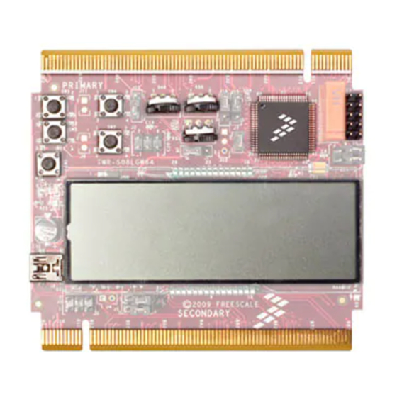
- Page 2 TOWER SYSTEM TOWER SYSTEM Get to Know the TWR-S08GW64 MC9S08GW64 Tamper Switch (SW4) Primary Connector User Switch (SW3) RS232 Port User Switch (SW5) Potentiometer to Control the Vrms Reset Switch Potentiometer to IRQ Switch Control Irms USB Connector LCD Glass Secondary Connector Figure 1: TWR-S08GW64...
- Page 3 Lab Tutorial for TWR-S08GW64 TOWER SYSTEM Introduction Freescale provides free lab diagnostic code to provide hands-on experience and demonstrate the capabilities of the MC9S08GW64 on TWR-S08GW64. Included: Lab 2: Lab 1: • LCD all segment ON for connectivity • Displays the current, voltage, energy check and power factor • LCD blink modes demonstration • Displays the clock, calendar and tampers registered • LCD charge pump and resistor bias...
- Page 4 TOWER SYSTEM Please follow the jumper 1 2 3 settings below before running Connect between 2 and 3 in J6 to get the Lab tutorial. power from the regulator. 1 2 3 1 2 3 1 2 3 Connect J7 to power up the MCU from the output of J6. 1 2 3 1 2 3 1 2 3 1 2 3 1 2 3 Connect between 2 and 3 in both J1 and...
- Page 5 1 2 3 1 2 3 J15 J16 Lab Tutorial for TWR-S08GW64 TOWER SYSTEM 1 2 3 J15 J16 Connect between 1 and 2 for both J15 Connect between 4 and 6 and between 3 and J16 to connect the output of QE8 and 5 for J14 to connect the GW64 serial to ADC1 and ADC2 for signal simulation data to RS232. input. J15 J16 Connect between 2 and 3 for J10 to connect Switch 4 as the tamper 1 input.
- Page 6 TOWER SYSTEM Step-by-Step Guide STEP STEP Open CodeWarrior and Install the GW64 the Project Service Pack 1. C omplete the setup instructions 1. Open the CodeWarrior window. in the Quick Start Guide. Be sure 2. Go to the “Help” menu. CodeWarrior v10.0 is installed. 3. S elect “Install New Software” in the 2. O pen CodeWarrior for drop down menu. microcontrollers. From the Windows 4.
- Page 7 Lab Tutorial for TWR-S08GW64 TOWER SYSTEM STEP Open the Source Code 2. E xpand “General” and select “CodeWarrior Classic Project Importer” as shown. Click “Next.” 1. I n the “File” menu go to “Import” as shown.
- Page 8 TOWER SYSTEM 3. B rowse to the folder where the code 4. T he project directory structure will be is stored and select the .mcp file and visible as shown. click “Finish.” In the CodeWarrior window, double click on MC9S08GW64.h in the Libs folder and paste the following line in the file: #pragma OPTION ADD S08CFv1Compatible “-BfaGapLimitBits4294967295”...
- Page 9 Lab Tutorial for TWR-S08GW64 TOWER SYSTEM 3. T ake the Serial Module and insert STEP Set Up the TWR- the PRIMARY connector side in the Primary Elevator, matching the “B” 9S08GW64 Module marking of the Elevator card and Basic steps for the Tower System the Serial Module in any of the three hardware installation remaining slots. For the LCD LAB, the following cards of 4. Take the Secondary Elevator card and the Tower System are required: fit it on the other side of the GW64 Controller and the Serial Module card,...
- Page 10 TOWER SYSTEM 1. Power up the Tower System by 2. C onnect the debugger for plugging the USB cable between the downloading the code from the PC by PC (USB Type-A Female connector) connecting the USB Cable from the and the Primary Elevator card PC (USB Type-A Female connector) connector J5 (Mini USB Type-B to the USB Multilink Interface (USB connector) and then switch ON the Type-B Female connector) and toggle switch (PWR SW) on the connect the other end of the USB Primary Elevator. Multilink Interface to the J2 of the GW64 Controller Card. Note: The red wire should match Pin 1 of J2.
- Page 11 Lab Tutorial for TWR-S08GW64 TOWER SYSTEM 3. C onfigure the HyperTerminal to use the 3. C onfigure the HyperTerminal with the DEMO9S08GW64 Lab as follows: following settings, as shown. 1. C onnect the serial cable between your PC and the serial module. 2. Open the HyperTerminal application and create a new connection on the COM port that connects to the UART on the board, as shown.
- Page 12 TOWER SYSTEM 2. S elect LCD_LAB-Standard-BDM_ STEP Start the P&E Toolkit PandE_Multilink_CyclonePro(1) as shown and click the “RUN” button. Application and Enter the Programmer/Debugger Steps to load the code Using CodeWarrior, compile and program the MC9S08GW64 microcontroller with the application by clicking on “RUN button drop down” as shown. 1. Click on Run Configuration.
- Page 13 Lab Tutorial for TWR-S08GW64 TOWER SYSTEM Lab 1: Demo • T he welcome message “GW64 DEMO” appears on the LCD. • By pressing switch “SW3,” the display scrolls between the main menus as shown: “GW64 DEMO” > “E METER” > “RTC DEMO” > “LCD DEMO” > “GW64 DEMO” • By pressing SW5, the user can access the sub menus of the main menus as follows: “ E METER” Keep pressing SW5 to scroll through the following: RMS current > RMS voltage > Active power >...
- Page 14 TOWER SYSTEM displayed. Then set the date using the SW3 SW5 POT 1 POT 2 POT 3 combination of SW3 and SW5. Hold (Tamper) for IRMS for IRMS for phase difference SW5 again for a few seconds to exit out of the date setting mode. • The time can be set in the same way that the date is set. You can further interact with the board in the following ways: • POT1: To change the value of Irms displayed • POT2: To change the value of Vrms...
- Page 15 Lab Tutorial for TWR-S08GW64 TOWER SYSTEM Lab 2: LCD 1. Type “help” to see the command help. The Lab 2 diagnostic takes commands through the HyperTerminal via the UART port, so make sure the UART cable is connected from board to the computer. Now the board is able to communicate to the DEMO9S08GW64 via the UART, as shown. 2. Type the commands and see the results on the board as shown.
- Page 16 TOWER SYSTEM TOWER SYSTEM Learn more at freescale.com/S08GW and freescale.com/Tower. Freescale, the Freescale logo and CodeWarrior are trademarks of Freescale Semiconductor, Inc., Reg. U.S. Pat. & Tm. Off. All other product or service names are the property of their respective owners. © 2010 Freescale Semiconductor, Inc. Doc Number: TWRS08GW64LBTUT / REV 0...
Need help?
Do you have a question about the freescale MC9S08GW64 and is the answer not in the manual?
Questions and answers