
Related Manuals for Rockwell Automation Allen-Bradley Ultra5000


Summary of Contents for Rockwell Automation Allen-Bradley Ultra5000
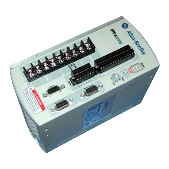
- Page 1 Ultra5000 Intelligent Positioning Drives Catalog Numbers (2098-IPD-005, -010, and -020) Installation Manual...
- Page 2 Reproduction of the contents of this copyrighted publication, in whole or part, without written permission of Rockwell Automation, is prohibited. Throughout this manual we use notes to make you aware of safety...
-
Page 3: Table Of Contents
Table of Contents Introduction ..........P-1 Preface Who Should Use this Manual . - Page 4 Table of Contents Wiring Your Ultra5000 ......... 2-16 Connecting Interface Cables .
- Page 5 Table of Contents Appendix C Chapter Objectives ..........C-1 Application Information Mechanical Resonance.
- Page 6 Table of Contents Publication 2098-IN001B-EN-P — July 2000...
-
Page 7: Preface
This manual describes the function and installation of the Ultra5000 products Purpose of this Manual and standard Rockwell Automation/Allen-Bradley motors recommended for use with the Ultra5000. The manual is intended for engineers or technicians directly involved in the installation, operation, and field maintenance of the Ultra5000. -
Page 8: Contents Of This Manual
Preface Refer to the following listing for the descriptive contents of this installation Contents of this Manual manual. Chapter Title Contents Preface Describes the purpose, background, and scope of this manual. Also specifies the audience for whom this manual is intended. Installing Your Ultra5000 Provides mounting information for the Ultra5000. -
Page 9: Product Receiving And Storage Responsibility
Preface You, the customer, are responsible for thoroughly inspecting the equipment Product Receiving and before accepting the shipment from the freight company. Check the item(s) Storage Responsibility you receive against your purchase order. If any items are obviously damaged, it is your responsibility to refuse delivery until the freight agent has noted the damage on the freight bill. - Page 10 Preface Publication 2098-IN001B-EN-P — July 2000...
-
Page 11: Installing Your Ultra5000
Chapter Installing Your Ultra5000 This chapter covers the following topics: Chapter Objectives • Complying with European Union directives • Before mounting your system • Bonding your system • Mounting your Ultra5000 drive The following information is a guideline for proper ATTENTION installation. -
Page 12: Low Voltage Directive
Installing Your Ultra5000 To meet CE requirements, the following additions are required: • You must run single-phase input wiring in a conduit that is grounded to the enclosure. • You must install a power line filter (Allen-Bradley catalog number 2090-UXLF-106, 2090-UXLF-110, 2090-UXLF-123 or equivalent based on system current) between the single-phase input line and the system module input. -
Page 13: Unpacking Modules
Installing Your Ultra5000 Unpacking Modules Each Ultra5000 ships with the following: • One Ultra5000 drive • One screwdriver • One instruction manual (publication 2098-IN001B-EN-P) • Two I/O connector plugs (14 and 28 pin) Remove all packing material, wedges, and braces from within and around the components. -
Page 14: Ventilation Requirements
Installing Your Ultra5000 Ventilation Requirements This section provides information to assist you in sizing your cabinet and locating your Ultra5000 drive(s) inside the cabinet. Figure 1.1 Minimum Clearance Requirements 50.8 mm (2.00 in.) Clearance for Airflow and Installation Allow 12.7 mm (0.5 in.) Allow 12.7 mm (0.5 in.) side clearance side clearance... -
Page 15: Transformer Sizing
Installing Your Ultra5000 Transformer Sizing The Ultra5000 does not require isolation transformers. A transformer may be required, however, to match the voltage requirements of the controller to the available service. To size a transformer, the power output (KVA) of each axis must be known. -
Page 16: Bonding Your System
Installing Your Ultra5000 Bonding is the practice of connecting metal chassis, assemblies, frames, shields Bonding Your System and enclosures to reduce the effects of electromagnetic interference (EMI). Bonding Modules Unless specified, most paints are not conductive, and they act as insulators. To achieve a good bond between modules and the subpanel, surfaces need to be paint-free or plated. -
Page 17: Bonding Multiple Subpanels
Installing Your Ultra5000 Bonding Multiple Subpanels Bonding multiple subpanels creates a common low impedance exit path for the high frequency energy inside the cabinet. Subpanels that are not bonded together may not share a common low impedance path. This difference in impedance may affect networks and other devices that span multiple panels. -
Page 18: Mounting Your Ultra5000 Drive
Installing Your Ultra5000 The procedures in this section assume you have prepared your panel and Mounting Your Ultra5000 understand how to bond your system. For installation instructions regarding Drive other equipment and accessories, refer to the instructions that came with each of the accessories for their specific requirements. -
Page 19: Connecting Your Ultra5000
Chapter Connecting Your Ultra5000 This chapter describes how to make wiring and cable connections for your Chapter Objectives Ultra5000. This chapter includes: • Understanding Ultra5000 connectors • Understanding Ultra5000 I/O specifications • Understanding encoder feedback specifications • Understanding serial interfaces •... -
Page 20: Front Panel Connections
Connecting Your Ultra5000 Front Panel Connections The following table provides a brief description of the Ultra5000 front panel connectors and describes the connector type. Designator Description Connector CN1A User Input/Output 28-Pin, 3.5mm, double-row, plugable spring clamp CN1B User Input/Output 14-Pin, 3.5mm, double-row, plugable spring clamp Motor Encoder 15-Pin, high-density D-shell CN3A... -
Page 21: I/O Connectors
Connecting Your Ultra5000 I/O Connectors CN1A (28-pin) and CN1B (14-pin) are plugable, double-row, spring clamp connectors with 3.5mm spacing and are included with your Ultra5000. The following table provides the signal description and pin-outs for the CN1A I/O connector. Signal Description CN1A Signal... -
Page 22: Motor Encoder Connector
Connecting Your Ultra5000 Motor Encoder Connector CN2 is a 15-pin high-density D-shell connector used for connection to the motor encoder. The following table provides the signal description and pin-outs for the CN2 motor encoder connector. Signal Description Signal Description Motor Encoder +Limit +Limit Channel A+... -
Page 23: Understanding Ultra5000 I/O Specifications
Connecting Your Ultra5000 A description of the Ultra5000 input/output specifications is provided on the Understanding Ultra5000 following pages. I/O Specifications Digital Inputs There are 16 general purpose digital inputs to use as needed. They are not connected in hardware to perform a particular function. Configure your digital inputs (as a group) as active IMPORTANT high (current sinking) or active low (current... -
Page 24: Digital Outputs
Connecting Your Ultra5000 The following table provides a description of the digital input specifications. Parameter Description Minimum Maximum ON State Voltage, Voltage applied to the input, with 10.8.V 26.4V Active High respect to IOCOM, to guarantee an ON Configuration state. ON State Voltage, Voltage applied to the input, with -26.4 V... - Page 25 Connecting Your Ultra5000 Figure 2.4 Transistor Output Hardware Configuration The following table provides a description of the digital (transistor) output specifications. Parameter Description Minimum Maximum ON State Current flow when the output transistor is ON — 50 mA Current OFF State Current flow when the output transistor is OFF —...
-
Page 26: Analog Inputs
Connecting Your Ultra5000 Analog Inputs There are two single-ended general purpose analog inputs to use as needed. A 12-bit sampling A/D converter generates the digital representation of the analog inputs. The following table provides a description of the analog input specifications. -
Page 27: Understanding Encoder Feedback Specifications
Connecting Your Ultra5000 The Ultra5000 offers two motor feedback interfaces. A description of the Understanding Encoder Ultra5000 encoder feedback specifications is provided starting below. Feedback Specifications Encoder Interface The Ultra5000 main encoder feedback connector is CN2. The motor encoder interface circuitry features include: •... -
Page 28: Auxiliary Encoder Interface
2-10 Connecting Your Ultra5000 The following table provides a description of the motor encoder interface specifications. Parameter Description Minimum Maximum AM, BM, and IM Input voltage difference between the + input and the - input that is +1.0 V +12.0 V ON State Input Voltage detected as an ON state. -
Page 29: Understanding Serial Interfaces
Connecting Your Ultra5000 2-11 The following table provides a description of the auxiliary encoder interface specifications. Parameter Description Minimum Maximum ON State Input Voltage Input voltage difference between the + input and the - input that is +1.0 V +12.0 V detected as an ON state. -
Page 30: Understanding Basic Wiring Requirements
2-12 Connecting Your Ultra5000 This section contains basic wiring information for the Ultra5000. Understanding Basic Wiring Requirements Plan the installation of your system so that you can ATTENTION perform all cutting, drilling, tapping, and welding with the system removed from the enclosure. Because the system is of the open type construction, be careful to keep any metal debris from falling into it. -
Page 31: Routing High And Low Voltage Cables
Connecting Your Ultra5000 2-13 Routing High and Low Voltage Cables Be aware that when you connect and route power and signal wiring on a machine or system, radiated noise from nearby relays (relay coils should have surge suppressors), transformers, and other electronic drives can be induced into motor or encoder feedback, communications, or other sensitive, low voltage signals. -
Page 32: Grounding Your Ultra5000
2-14 Connecting Your Ultra5000 We recommend that all equipment and components of a machine or process Grounding Your Ultra5000 system have a common earth ground point connected to their chassis. A grounded system provides a safety ground path for short circuit protection. Grounding your modules and panels minimizes shock hazards to personnel and damage to equipment caused by short circuits, transient overvoltages, and accidental connection of energized conductors to the equipment chassis. -
Page 33: Grounding Multiple Subpanels
Connecting Your Ultra5000 2-15 Grounding Multiple Subpanels To ground multiple subpanels, refer to the figure below. Figure 2.10 Subpanels Connected to a Single Ground Point Always follow NEC and applicable local codes Ground grid or power distribution ground EMC Motor Ground Termination For F-Series, H-Series, and N-Series motors the factory supplied power cables are shielded. -
Page 34: Wiring Your Ultra5000
2-16 Connecting Your Ultra5000 Figure 2.11 Motor Cable EMC Shield Connection Ultra5000 Motor Cable Jacket Clamp Shield Motor Cable Jacket Y-Series motors have a short pigtail cable which connects to the motor, but is not shielded. These motor power cables have a 152.4 mm (6.0 in.) shield termination wire with a ring lug that connects to the closest earth ground. -
Page 35: Connecting Interface Cables
Connecting Your Ultra5000 2-17 The following sections provide information and procedures on how to wire your Ultra5000. Connecting Interface Cables Connect all interface cables as shown in the table below. This cable: Plugs into this connector: 28-pin, Digital I/O CN1A 14-pin, Auxiliary encoder/analog I/O CN1B 15-pin, Motor encoder feedback 9-pin, Main serial port... -
Page 36: Wiring Power Connections
2-18 Connecting Your Ultra5000 Wiring Power Connections The Ultra5000 requires single phase AC power, 100 to 240 VAC. The input power may be optionally isolated through a transformer. Field wiring must be copper, with 75°C (194°F) minimum rating. The phasing of L1 and L2/N is arbitrary. - Page 37 Connecting Your Ultra5000 2-19 2. Check for continuity in the motor leads (wires marked U, V, and W). Verify that the resistance reading from each wire to earth ground is above 500k ohms. If your resistance reading is: Then: Above 500k ohms Go to main step 3.
- Page 38 2-20 Connecting Your Ultra5000 5. Tighten each screw with a torque of 1.25 Nm (11 lb-in.). 6. Gently pull on each wire to make sure it does not come out of its terminal. Re-insert and tighten any loose wires. If your motor is: Then: F-Series, H-Series, or N-Series Go to Connecting F-Series, H-Series,...
- Page 39 Connecting Your Ultra5000 2-21 Figure 2.15 Ultra5000 Power Wiring Diagram Publication 2098-IN001B-EN-P — July 2000...
- Page 40 2-22 Connecting Your Ultra5000 Publication 2098-IN001B-EN-P — July 2000...
-
Page 41: Commissioning Your Ultra5000
Chapter Commissioning Your Ultra5000 This chapter provides you with information to power up and start your Chapter Objectives Ultra5000. This chapter includes: • General startup precautions • Understanding communication switch settings • Applying power to your system • Configuring your Ultra5000 Before you begin these procedures, be sure to read and understand the information in the previous chapters of this manual. -
Page 42: Understanding Communication Switch Settings
Commissioning Your Ultra5000 The Ultra5000 communication address selector switches (MSD and LSD) Understanding allow setting a unique address for each Ultra5000 connected on a serial Communication Switch network. The switches allow setting addresses 0-99. Refer to Figure 2.2 for the Settings switch locations. -
Page 43: Configuring Your Ultra5000
Commissioning Your Ultra5000 3. Set the communication address switches as shown in the example table below. For the location of the address switches, refer to Figure 2.2. For example, if Set the MSD Set the LSD you have: switch to: switch to: 1 drive 2 drives... - Page 44 Commissioning Your Ultra5000 3. Click on the Stop Scanning button when your drive is detected or wait for the scanning to time out. 4. Look for the Ultra5k icon under the On-Line Drives tree. The Ultra5k icon indicates that your drive is detected. If your Ultra5000 drive: Then: Is detected and listed under the On-Line...
-
Page 45: Maintaining Your Ultra5000
Chapter Maintaining Your Ultra5000 This chapter covers the following topics: Chapter Objectives • Maintaining the drive • Troubleshooting The Ultra5000 Drive is designed to function with a minimum of maintenance. Maintaining the Drive DC bus capacitors may retain hazardous voltages after ATTENTION input power has been removed, but will normally discharge in several seconds. -
Page 46: Troubleshooting
Maintaining Your Ultra5000 The normal state of the 7-segment LED is to actively cycle its segments and Troubleshooting show an illuminated decimal point that indicates +5 volts. Refer to the table below to identify problems, potential causes, and appropriate actions to take to resolve the problems. - Page 47 Maintaining Your Ultra5000 Error Problem or Possible Cause(s) Action/Solution Code Symptom Low AC line/AC power input. Verify voltage level of the incoming AC power. Undervoltage 100V AC minimum for safe Ultra5000 operation. Check AC power source for glitches or line drop (below 90V AC).
- Page 48 Maintaining Your Ultra5000 Publication 2098-IN001B-EN-P — July 2000...
-
Page 49: Specifications And Dimensions
Appendix Specifications and Dimensions This chapter covers: Chapter Objectives • Ultra5000 specifications • Dimensions This section lists the specifications for the Ultra5000. Ultra5000 Specifications General Power Specifications The table below lists general power specifications and requirements. Specification Description IPD-005 IPD-010 IPD-020 AC Input 100-240 Vac... -
Page 50: Physical And Environmental
Specifications and Dimensions Physical and Environmental The table below lists physical and environmental specifications and requirements. Specification Description IPD-005 1.77 Kg (3.9 lbs) IPD-010 2.06 Kg (4.55 lbs) IPD-020 2.05 Kg (4.51 lbs) Operating Temperature 0 C to 55 C (32 F to 131 Storage Temperature C to 70... -
Page 51: User Programming
Specifications and Dimensions User Programming The table below lists physical and programming specifications. Specification Description Language Compiled ANSI C with Library of Motion Functions Programming Environment Full-featured Color Syntax Editor and C Compiler Integrated with Ultraware Operating System Real-time, multi-tasking, field upgradable flash User Program Memory 512 Kbytes Flash Memory, 100,000 Write Cycles... -
Page 52: Inputs And Outputs
Specifications and Dimensions Inputs and Outputs The table below lists I/O specifications. Specification Description General Purpose Digital Inputs 16 Optically Isolated 12-24 Volt Inputs Inputs/Outputs - Software Selectable as a Group to be Active High, Sinking/Sourcing Selection Current Sinking or Active Low, Current Sourcing General Purpose Digital Outputs 7 Optically Isolated 12-24 Volt Outputs - 50 Milliamperes Maximum... -
Page 53: Auxiliary Feedback
Specifications and Dimensions Auxiliary Feedback The table below lists auxiliary feedback specifications. Specification Description Operation Auxiliary Feedback Input Input Modes A quad B Input Type Line Receiver Maximum Input Frequency 2.5 MHz (Encoder Lines) Connectors The table below lists connector specifications. Specification Description Digital I/O Connector CN1A 28 Position Plugable Spring Clamp Terminal Block... -
Page 54: Dimensions
Specifications and Dimensions The following diagrams show the dimensions and mounting hole locations for Dimensions the 2098-IPD-005, -010, and -020. Figure A.1 Ultra5000 500W Mounting Diagram 83.82 mm (3.30 in.) 131.83 mm 43.18 mm 20.32 mm 5.19 in. 1.70 in. .80 in. - Page 55 Specifications and Dimensions Figure A.2 Ultra5000 1 kW & 2 kW Mounting Diagram 63.82 mm (2.51 in.) 43.18 mm 20.32 mm 131.83 mm (1.70 in.) (0.80 in.) (5.19 in.) 205.23 mm 184.91 mm 193.55 mm (8.08 in.) (7.62 in.) (7.28 in.) 144.53 mm (5.89 in.) 114.30 mm...
- Page 56 Specifications and Dimensions Publication 2098-IN001B-EN-P — July 2000...
-
Page 57: Options And Accessories
Appendix Options and Accessories This appendix provides the Ultra5000 options and accessory catalog numbers. Chapter Objectives This appendix covers catalog numbers for the: • Ultra5000 family • Ultra5000 accessories • Motor power cables • Motor feedback cables • Interface cables Contact your local Allen-Bradley sales office for additional information. -
Page 58: External Shunt Kit
Options and Accessories Ultra5000 Accessories External Shunt Kit Only the Active Shunt can be used with the Ultra5000. Use the following table to identify your External Shunt. Description Catalog Number Active Shunt Module (300W) 2090-UCSR-A300 Ferrites are used at both ends of the DC Bus wires for CE radiated emissions compliance. -
Page 59: Mating Connector Kits
Options and Accessories Mating Connector Kits The Ultra5000 has two serial connectors, one motor feedback connector, two I/O connectors and one terminal block for power connections. Connectors are D-shell type except for the terminal block connector and the I/O connectors. The I/O connectors are plugable connectors and are not available in a connector kit. -
Page 60: Motor Power Cables
Options and Accessories Use the following table to identify motor power cables for your F, H, MP, N, Motor Power Cables and Y-Series motors. Length of cable xx is in meters (01, 03, 09, 15, and 30). Description Catalog Number H-2000/3000 Series Motor Power Cable, 2090-UXNPA-H16S up to 2 kW Ultra3000/5000, (non flex, 16 AWG, straight angle) -
Page 61: Interface Cables
Options and Accessories Use the following table to identify controller cables for your Interface Cables Ultra5000. Length of cable xx is in meters (01, 03, 09, and 15). Description Catalog Number Interface Cable to Ultra3000/5000 (Computer Connection) 2090-UXPC-D09xx Publication 2098-IN001B-EN-P — July 2000... - Page 62 Options and Accessories Publication 2098-IN001B-EN-P — July 2000...
-
Page 63: Application Information
Appendix Application Information The following information is considered application specific and does not Chapter Objectives apply to all installations. This appendix covers the following topics: • Mechanical resonance • Using an emergency stop contactor • Grounding for Ultra5000 CE requirements •... -
Page 64: Backlash
Application Information Backlash Backlash between the motor and load effectively unloads the motor over a small angle. Within this small angle, the increased gain can result in oscillations. Some backlash may be unavoidable, especially with gear reduction. If backlash is present, the inertia match between the load and motor must be properly sized for good servo performance (load inertia should roughly equal motor inertia). - Page 65 Application Information Shield and ground cable connection methods are shown in Figure C.1. Implementation of safety circuits and risk assessment is the ATTENTION responsibility of the machine builder. Please reference international standards EN1050 and EN954 estimation and safety performance categories. For more information refer to Understanding the Machinery Directive (publication SHB-900).
-
Page 66: Grounding For Ultra5000 Ce Requirements
Application Information Refer to the figure below for Ultra5000 CE requirements. Grounding for Ultra5000 CE Requirements Figure C.2 Ultra5000 CE Requirements Enclosure Ground Conduit to Enclosure Single-Phase User-Supplied Mains with Discrete I/O Filter Ground User-Supplied Conduit Clamp Power Source Unfiltered Conductors Filtered Conductors Single-Phase... -
Page 67: Building Your Own Cables
Application Information This section provides information to assist you in building your own cables. Building Your Own Cables Allen-Bradley power and feedback cables are available and recommended for robust system integrity to EMI. Refer to Appendix B for cable catalog number information. - Page 68 Application Information Figure C.3 T T T T o o o o r r r r r r r r o o o o i i i i d d d d E E E E n n n n c c c c od od od ode e e e r r r r S S S S h h h h i i i i e e e e l l l l d d d d i i i i ng ng ng ng M M M M e e e e t t t t ho ho ho hod d d d f f f f o o o o r r r r B B B B r r r r u u u u s s s s h h h h l l l l e e e e ss ss ss ss S S S S e e e e r r r r v v v v o o o o M M M M o o o o t t t t o o o o r r r r s s s s Ultra5000 Brushless Motor...
- Page 69 Index breakout boards B-3 external shunt kit B-2 A/D converter 2-8 interface cables B-5 mating connector kits B-3 Coils suppressed with RC filters C-5 motor feedback cables B-4 Current motor power cables B-4 input A-1 Ultra5000 family B-1 Frequency, input A-1 Power 2-18 filter requirements C-4 Voltage, input A-1...
- Page 70 Index Documentation Emergency Stop Contactor C-2 Related P-2 IPM Short, see Troubleshooting IPM Thermal Protection Fault, see Troubleshooting motor ground termination, F, H, N-series motors 2-15 low voltage directive 1-2 motor ground termination, Y-series motors 2-16 Emergency stop contactor C-2 Maintenance 4-1 EMI (ElectroMagnetic Interference) Cleaning 4-1...
- Page 71 Index Applying Power 3-2 Power Output dissipation A-2 Continuous A-1 Losses A-2 Peak A-1 Output Shock A-2 Continuous A-1 Storage Temperature A-2 Peak A-1 user programming A-3 Wiring Diagram 2-21 Vibration A-2 Power Supply Protection 2-18 weight, Ultra5000 A-2 Precautions specifications and dimensions A-1 General Startup 3-1 dimensions A-6...
- Page 72 Index Connecting I/F Cables 2-17 I/O Connections 2-17 Vibration A-2 Power Connections 2-18 procedure 2-18 Wiring Diagram 2-21 Wiring 2-16 Publication 2098-IN001B-EN-P — July 2000...
- Page 73 www.ab.com/motion For more information refer to our web site: Publication 2098-IN001B-EN-P — July 2000 PN 0013-1079-001-01 Supersedes Publication 2098-IN001A-EN-P — June 2000 Copyright 2000 Rockwell International Corporation. Printed in USA.
Need help?
Do you have a question about the Allen-Bradley Ultra5000 and is the answer not in the manual?
Questions and answers