Sign In
Upload
Manuals
Brands
Rockwell Automation Manuals
DC Drives
Allen-Bradley Ultra5000
Rockwell Automation Allen-Bradley Ultra5000 Manuals
Manuals and User Guides for Rockwell Automation Allen-Bradley Ultra5000. We have
2
Rockwell Automation Allen-Bradley Ultra5000 manuals available for free PDF download: Installation Manual
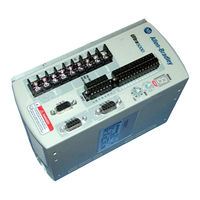
Rockwell Automation Allen-Bradley Ultra5000 Installation Manual (160 pages)
Intelligent Positioning Drives
Brand:
Rockwell Automation
| Category:
Control Systems
| Size: 5.8 MB
Table of Contents
Table of Contents
3
Contents of this Manual
9
Preface
9
Purpose of this Manual
9
Who Should Use this Manual
9
Related Documentation
11
Conventions Used in this Manual
12
Product Receiving and Storage Responsibility
12
Allen-Bradley Support
13
Local Product Support
13
Technical Product Assistance
13
Comments Regarding this Manual
13
Introduction
9
Appendix A Objectives
15
Complying with European Union Directives
15
Chapter 1 Chapter Objectives
15
Installing Your Ultra5000
15
EMC Directive
16
Low Voltage Directive
16
Before Mounting Your System
17
How to Store Your Ultra5000 before Installation
17
How to Unpack the System
18
Minimum Mounting Requirements
19
Ventilation Requirements
20
Sizing an Enclosure
21
Transformer Sizing
21
Data
21
Fuse Sizing
23
General Power Specifications
23
Bonding Your System
24
Bonding Modules
24
Bonding Multiple Subpanels
25
Mounting Your Ultra5000 Drive
26
Chapter 2
27
Chapter Objectives
27
Ultra5000 Connector
27
Understanding Ultra5000 Controller Functions
28
Ultra5000 Block Diagram
28
Understanding Ultra5000 Connectors
29
230V Ultra5000 Front Panel Connections
30
Kw, and 2 Kw Ultra5000 (2098-IPD-005, -010, and -020)
30
I/O Connectors
31
Motor Encoder Connector
32
Serial Port Connectors
33
Terminal Block
33
Kw Ultra5000 (2098-IPD-030)
34
Terminal Blocks
35
Kw, and 15 Kw Ultra5000 (2098-IPD-075, and -150)
36
I/O Connectors
37
Motor Encoder Connector
37
Serial Port Connectors
37
Terminal Blocks
37
230V Ultra5000 with Devicenet Front Panel Connections
39
Kw, and 2 Kw Ultra5000 with Devicenet (2098-IPD-005-DN, -010-DN, and -020-DN)
39
I/O Connectors
40
Motor Encoder Connector
40
Serial Port Connectors
40
Devicenet Connector
40
Kw, 7.5 Kw, and 15 Kw Ultra5000 (2098-IPD-005-DN, -010-DN, and -020-DN)
41
460V Ultra5000 Front Panel Connections
42
I/O Connectors
43
Motor Encoder Connector
43
Serial Port Connectors
43
Terminal Blocks
43
Understanding Ultra5000 I/O Specifications
45
Digital I/O Power Supply
45
Digital Inputs
46
Digital Outputs
48
Analog Inputs
49
Analog Outputs
50
Understanding Motor Encoder Feedback Specifications
51
AM, BM, and IM Inputs
51
Hall Inputs
53
Thermostat Input
53
Limit and - Limit Inputs
54
Encoder Phasing
55
Motor Encoder Connection Diagram
57
Unbuffered Motor Encoder Outputs
57
Buffered Motor Encoder Outputs
57
Understanding Auxiliary Encoder Feedback Specifications
58
Auxiliary Encoder Interface
58
Understanding the Serial Interface
60
Default Serial Interface Settings
60
Connecting Your Ultra5000
61
Powering the Digital I/O
61
Accessing the Internal Digital I/O Power Supply
62
Understanding Basic Wiring Requirements
64
Building Your Own Cables
64
Routing High and Low Voltage Cables
65
Grounding Your Ultra5000
66
Grounding Your System to the Subpanel
66
Grounding Multiple Subpanels
67
Motor Power Cable Shield Termination
67
Wiring Your Ultra5000
69
Connecting Interface Cables
69
Wiring I/O Connections
69
Connecting to a Devicenet Network
70
Connecting Your Devicenet Cable
71
Assigning Your Ultra5000 Devicenet Address
72
Wiring Power Connections
74
Chapter 3
61
Chapter Objectives
61
Chapter 4
81
Chapter Objectives
81
Commissioning Your Ultra5000
81
General Startup Precautions
81
Understanding Communication Switch Settings
82
Applying Power to Your System
83
Configuring Your Ultra5000
84
Chapter 5
87
Chapter Objectives
87
Maintaining the Drive
87
Periodic Maintenance
87
Cleaning the Drive
87
Inspecting the Cables
88
Maintaining Your Ultra5000
87
General Troubleshooting
88
Error Codes
88
Troubleshooting for Devicenet Drives
92
Devicenet Module Status LED
92
Devicenet Network Status LED
93
Node Problems
94
Device Failure - LED Status Check
94
Scanner Problems
95
Power Supply Problems
95
Cable Installation and Design Problems
96
Adjusting the Physical Network Configuration
96
2098-IPD-005-XX, -010-XX, and -020-XX
97
2098-IPD-030-XX, -075-XX, and -150-XX
98
2098-IPD-HV030-XX, -HV050-XX, -HV100-XX, -HV150-XX
99
Physical and Environmental
100
Power Dissipation
101
User Programming
102
Control
102
Inputs and Outputs
103
Communications
103
Motor Feedback
104
Auxiliary Feedback
104
Connectors
104
Dimensions
105
Appendix B
113
Interconnect Diagrams
113
Objectives
113
Ultra5000 and Motor Cable Diagrams
113
Ultra5000 Drive and Motor Cable Combinations
113
Ultra5000 to Motor Interconnect Diagrams
115
Ultra5000 Power Wiring Diagrams
127
Using an Emergency Stop Contactor
132
Grounding for Ultra5000 CE Requirements
134
Ultra5000 Shunt Module Information
135
300 Watt Active Shunt Module
135
900 Watt Passive Shunt Module
136
2090 Passive Shunt Module
136
Appendix C
136
Ultra5000 Drives
136
AC Line Filters
137
Ultraware Software
137
External Shunt Kits
140
300 Watt Active Shunt Ferrites
141
2090 Series Passive Shunts
141
Cables
142
Motor Power Cables
142
Motor Feedback Cables
143
MP-Series Motor Brake Cable
144
Ultra5000 Interface Cables
144
Mating Connector Kits
145
Appendix D
147
Applicable Drives
147
Mandatory Neutral Connection of Isolation Transformer
147
Adding a Safety Ground to the Isolation Transformer
149
Objectives
147
Wiring Three Phase Power to a
147
Three Phase Line Filtering Requirements for EMC
149
Voiding of CE Compliance
150
Advertisement
Rockwell Automation Allen-Bradley Ultra5000 Installation Manual (73 pages)
Intelligent Positioning Drives
Brand:
Rockwell Automation
| Category:
DC Drives
| Size: 1.27 MB
Table of Contents
Table of Contents
3
Preface
7
Introduction
7
Who Should Use this Manual
7
Purpose of this Manual
7
Contents of this Manual
8
Related Documentation
8
Conventions Used in this Manual
8
Product Receiving and Storage Responsibility
9
Allen-Bradley Support
9
Local Product Support
9
Technical Product Assistance
9
Installing Your Ultra5000
11
Chapter Objectives
11
Complying with European Union Directives
11
EMC Directive
11
Low Voltage Directive
12
Before Mounting Your System
12
Storing Your Ultra5000 before Installation
12
Unpacking Modules
13
System Mounting Requirements
13
Ventilation Requirements
14
Transformer Sizing
15
Bonding Your System
16
Bonding Modules
16
Bonding Multiple Subpanels
17
Mounting Your Ultra5000 Drive
18
Connecting Your Ultra5000
19
Chapter Objectives
19
Understanding Ultra5000 Connectors
19
Ultra5000 Block Diagram
19
Front Panel Connections
20
I/O Connectors
21
Motor Encoder Connector
22
Serial Port Connectors
22
Understanding Ultra5000 I/O Specifications
23
Digital Inputs
23
Digital Outputs
24
Analog Inputs
26
Analog Outputs
26
Understanding Encoder Feedback Specifications
27
Encoder Interface
27
Auxiliary Encoder Interface
28
Understanding Serial Interfaces
29
Understanding Basic Wiring Requirements
30
Routing High and Low Voltage Cables
31
Grounding Your Ultra5000
32
Grounding Your System to the Subpanel
32
Grounding Multiple Subpanels
33
EMC Motor Ground Termination
33
Wiring Your Ultra5000
34
Connecting Interface Cables
35
Wiring I/O Connections
35
Wiring Power Connections
36
Commissioning Your Ultra5000
41
Chapter Objectives
41
General Startup Precautions
41
Understanding Communication Switch Settings
42
Applying Power to Your System
42
Configuring Your Ultra5000
43
Maintaining Your Ultra5000
45
Chapter Objectives
45
Maintaining the Drive
45
Periodic Maintenance
45
Troubleshooting
46
Error Codes
46
Specifications and Dimensions
49
Chapter Objectives
49
Ultra5000 Specifications
49
General Power Specifications
49
Physical and Environmental
50
Power Dissipation
50
User Programming
51
Controller
51
Inputs and Outputs
52
Communications
52
Motor Feedback
52
Auxiliary Feedback
53
Connectors
53
Dimensions
54
Options and Accessories
57
Chapter Objectives
57
Ultra5000 Family
57
Option Cards
57
Ultra5000 Accessories
57
External Shunt Kit
58
AC Line Filters
58
Mating Connector Kits
59
Break out Board, Cables, and Kits
59
Motor Power Cables
60
Motor Feedback Cables
60
Interface Cables
61
Application Information
63
Chapter Objectives
63
Mechanical Resonance
63
Backlash
64
Using an Emergency Stop Contactor
64
Grounding for Ultra5000 CE Requirements
66
Building Your Own Cables
67
Persistent EMI Problems
67
Advertisement
Related Products
Rockwell Automation Allen-Bradley 1204-TFA1, Allen-Bradley 1204-TFB2
Rockwell Automation Allen-Bradley PowerFlex 6000
Rockwell Automation Allen-Bradley PowerFlex Active Front End Series
Rockwell Automation Allen-Bradley PowerFlex AFE
Rockwell Automation Allen-Bradley PowerFlex 755TL Series
Rockwell Automation Allen-Bradley PowerFlex 755TR Series
Rockwell Automation Allen-Bradley PowerFlex 755TM Series
Rockwell Automation Allen-Bradley PowerFlex 755
Rockwell Automation Allen-Bradley IMPACT 1336 Series
Rockwell Automation Allen-Bradley PowerFlex 700 Series
Rockwell Automation Categories
Controller
Control Unit
Power Supply
DC Drives
Industrial Equipment
More Rockwell Automation Manuals
Login
Sign In
OR
Sign in with Facebook
Sign in with Google
Upload manual
Upload from disk
Upload from URL