Sign In
Upload
Download
Table of Contents
Contents
Add to my manuals
Delete from my manuals
Share
URL of this page:
HTML Link:
Bookmark this page
Add
Manual will be automatically added to "My Manuals"
Print this page
×
Bookmark added
×
Added to my manuals
Manuals
Brands
FAAC Manuals
Door Opening System
DAAB MT
User instructions
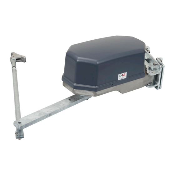
FAAC DAAB MT User Instructions
Drive unit
Hide thumbs
1
Table Of Contents
2
3
4
5
6
7
8
9
10
11
12
13
14
15
16
17
18
19
20
21
22
23
24
25
26
27
28
29
30
page
of
30
Go
/
30
Contents
Table of Contents
Bookmarks
Table of Contents
Table of Contents
EU Declaration of Incorporation
Safety
General
Packing, Transport and Unpacking
Introduction
Intended Use
Machine Marking
Manufacturer
Drive Unit MA2/MK2
Function Description
Design and Function
Dimensions
Technical Specification
Electric Motors
Gears
Installation and Commissioning
General Installation
Side Installation
Mounting Plate
Drive Arm
Gate Mounting and Link Arm
Top Mounting
Bracket & Mounting Plate
Drive Arm
Gate Mounting
Link Arm
Top Mounting with Limited Lateral Space
Bracket & Mounting Plate
Drive Arm
Gate Mounting
Mounting Plate for the Swing Arm Bracket
Link Arm
Wing Mounting
Bracket & Mounting Plate
Drive Arm
Installing the Drive Unit
Drive Unit MT
Function Description
Design and Function
Dimensions
Technical Specification
Electric Motors
Gears
Installation and Commissioning
General Installation
Side Installation
Mounting Plate
Drive Arm
Gate Mounting and Link Arm
Top Mounting
Bracket & Mounting Plate
Drive Arm
Gate Mounting
Link Arm
Top Mounting with Limited Lateral Space
Bracket & Mounting Plate
Drive Arm
Gate Mounting
Mounting Plate for the Swing Arm Bracket
Link Arm
Adjusting the Drive Unit
Disengagement
Quick Release
Release Handle
Electrical Connection
General
Engaging the Electric Motor
Limit Positions
Maintenance and Service
General
Lubrication
Oil Filled Gearbox
Open Gearbox
Spare Parts
Fault Search
In the Event of a Blockage
In the Event of a Collision
The Motor Is Running but the Gate Is Not Moving
Advertisement
Quick Links
Download this manual
USER INSTRUCTIONS
DAAB DRIVE UNIT MT/MK2/MA2/M10
Issue 1
FAAC Nordic AB
BOX 125, SE-284 22 PERSTORP SWEDEN TEL. +46 435 77 95 00 FAX. +46 435 77 95 29
www.faac.se
Table of
Contents
Previous
Page
Next
Page
1
2
3
4
5
Advertisement
Table of Contents
Need help?
Do you have a question about the DAAB MT and is the answer not in the manual?
Ask a question
Questions and answers
Related Manuals for FAAC DAAB MT
Door Opening System FAAC DOMOSWING battery Quick Start Manual
(7 pages)
Door Opening System FAAC DAAB M10 User Instructions
Drive unit (30 pages)
Door Opening System FAAC 412 Manual
Automation system (27 pages)
Door Opening System FAAC 392 Translation Of The Original Instructions
(24 pages)
Door Opening System FAAC A1400 AIR RDT Manual
(118 pages)
Door Opening System FAAC A140 AIR Series Manual
(70 pages)
Door Opening System FAAC A100 Compact Manual
(61 pages)
Door Opening System FAAC A1000 User Manual
(116 pages)
Door Opening System FAAC 950N Manual
Swing door operator (31 pages)
Door Opening System FAAC A1400 AIR Manual
(130 pages)
Door Opening System FAAC A951 Manual
(66 pages)
Door Opening System FAAC 750 Instruction Manual
(14 pages)
Door Opening System FAAC 950N2 Quick Start Manual
(4 pages)
Door Opening System FAAC A952 Quick Start Manual
(6 pages)
Door Opening System FAAC A952 Manual
(94 pages)
Door Opening System FAAC A140 AIR-T Series Manual
(76 pages)
This manual is also suitable for:
Daab mk2
Daab ma2
Daab m10
Table of Contents
Print
Rename the bookmark
Delete bookmark?
Delete from my manuals?
Login
Sign In
OR
Sign in with Facebook
Sign in with Google
Upload manual
Upload from disk
Upload from URL


Need help?
Do you have a question about the DAAB MT and is the answer not in the manual?
Questions and answers