Table of Contents
Advertisement
Advertisement
Table of Contents

Related Manuals for FAAC A100 Compact


Summary of Contents for FAAC A100 Compact
- Page 1 A100 Compact EN16005...
- Page 3 : Description : Linear sliding door to 1 or 2 leaf Model : A100 Compact the essential requirements of the following EC directive (including all applicable amendments) • 2006/42/EC Machinery Directive have been applied and fulfilled, and that the relevant technical documentation is compiled in accordance with part B of Annex VII of the above mentioned Machinery Directive.
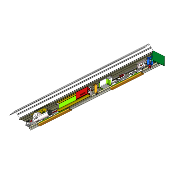
- Page 4 Closing housings (fig. 1 ref. sliding doors. This is the aluminium profile enabling closure of the automated The FAAC series A100 COMPACT automated systems are supplied system. The side panels (fig.1 ref. ) completely close the completely assembled, wired and tested in the configuration system.
- Page 5 DOOR FRAME ACCESSORIES To facilitate the door profile to adapt to the carriages and to enable correct finish of the installation, FAAC offers the following series of articles: Pair of sliding blocks (fig. 12-13 ref. Supplied as a pair, they can be secured on a wall (or on the fixed leaf) or directly on the floor.
- Page 6 KEY TO PROFILES SUPPORT PROFILE HOUSING PROFILE LEAF FITTING PROFILE LOWER GUIDE PROFILE GRIPPER FOR GLASS LEAF LOWER SLIDING BLOCK FOR GLASS LEAF SEAL FOR COVER OF CABLE ROUTING COMPARTMENT...
- Page 7 A100 COMPACT 43.6 HA = (LH + 3) ± 7,5mm HA = Leaf height LH = height off the floor, level with lower housing side The calculation of leaf height refers to the articulated sliding block. If using the fixed sliding block, refer to the specific instructions fig.
- Page 8 A100 COMPACT glass leaf 43.6 25.8 HA = (LH - 18,5) ± 7,5mm HA = Leaf height LH = height off the floor, level with lower housing side fig. 4...
- Page 9 A100 COMPACT Right Opening Single Leaf 1500 1892 1700 2092 1900 2292 1075 1000 2100 2492 1175 1100 2300 2692 1275 1200 2500 2892 1375 1300 2700 1059 1025 3092 1475 1400 2900 1159 1125 3292 1575 1500 3100 1259...
- Page 10 A100 COMPACT Left Opening Single Leaf 1500 1892 1700 2092 1900 2292 1075 1000 2100 2492 1175 1100 2300 2692 1275 1200 2500 2892 1375 1300 2700 1059 1025 3092 1475 1400 2900 1159 1125 3292 1575 1500 3100 1259...
- Page 11 A100 COMPACT Double Leaf 1700 2742 1300 1900 2942 1400 1000 2100 3142 1500 1100 2300 3342 1600 1200 2500 3542 1700 1300 2700 3742 1800 1400 2900 3942 1900 1500 3100 4142 2000 1600 3300 4342 2100 1700 3500...
- Page 12 INSTALLATION OF ASSEMBLED AUTOMATED SYSTEM PREPARING THE SUPPORT PROFILE 1.1A SUPPORT PROFILE - SECURING ON WALL The support profile is used to secure the automated system to a Define the exact height position of the support profile, considering load bearing structure in metal or masonry , free of any significant the dimensions of fig.3 and - for doors with glass leaves - in deformation.
- Page 13 INSTALLING THE LOWER SLIDING BLOCKS The lower sliding blocks are designed for securing to a wall (or fixed leaf) or to the floor. Assemble the sliding blocks, referring to the dimensions in figures 12 and 13. On-wall securing (or on fixed leaf): •...
- Page 14 4.3A ADJUSTING THE COUNTER-THRUST WHEEL The carriages have a counter-thrust wheel which prevents them from coming out of their seat. The wheel must be adjusted so that it does not press on the support profile, to thus avoid increased friction. Counter-thrust wheel adjustment procedure: •...
- Page 15 6A ADJUSTING THE CLOSING MECHANICAL STOPS (DOUBLE LEAF) The automatic door is supplied with the closing mechanical stops installed on the mid-point of the support profile. If the door centre requires adjustment, proceed as follows: • Check if the mechanical stops are at the centre of the profile.
- Page 16 ADJUSTING THE BELT FASTENING ON CARRIAGES The automated system is supplied with the belt fastened to the carriages by the fastening fittings (Fig. 22 ref. ) It is usually unnecessary to modify this fastening, but, if it is necessary to adjust finely, proceed as follows: •...
- Page 17 ADJUSTING BELT TENSION Make sure that the belt is not too loose or too taut. Belt tensioning procedure: • Loosen the nut (Fig. 23 ref. • Turn the screw and bolt (Fig. 23 ref. ) to tighten or loosen the belt. •...
- Page 18 INSTALLING THE CLOSING HOUSING • Lay the closing housing on the spacers you had previously mounted, as shown in Fig. 26 • To keep the housing open, lift it (Fig. 26 ref. ) and push it If you are using the internal release, in order to close (Fig.26 ref.
- Page 19 If there is no play, proceed as follows: MOTOR LOCK •Loosen the two screws (fig. 28 ref. ) which connect the belt fit- The motor locking device guarantees that the leaves are locked ting to the drive carriage (on both carriages for double leaves). when closed.
- Page 20 START-UP OF THE AUTOMATED SYSTEM • Manually check correct sliding of the leaves and of all the moving elements. • Carry out/check the electrical connections on the control board of the power cables coming from the power supply unit, from the motor, and from all accessories, consulting the instructions of the control board.
- Page 21 ASSEMBLY OF IN-KIT AUTOMATED SYSTEMS This section describes the assembly of the in-kit automated systems. After you have prepared the necessary profiles, we advise you to assemble and install at the same time. PREPARING THE SUPPORT PROFILE Support profiles are available in two sizes: 4300 mm or 6100 mm.
- Page 22 1.3B POSITIONING OF THE LIMIT SWITCH. Fit four plates on the ends of the support profile (fig.32), two for the central stops and two for the side stops. fig. 32 Install the mechanical stops as shown in Fig. 33, using the supplied screws.
- Page 23 PREPARING THE LEAVES INSTALLING THE LOWER SLIDING BLOCKS Refer to chapter 2A of the assembled automated system Refer to chapter 3A of the assembled automated system installation. installation. ADJUSTING THE LEAVES ADJUSTING THE MECHANICAL STOPS Refer to chapter 4A of the assembled automated system Refer to chapter 5A and 6A of the assembled automated system installation.
- Page 24 ADJUSTING THE BELT FASTENING ADJUSTING BELT TENSION Refer to chapter 7A of the assembled automated system Refer to chapter 8A of the assembled automated system installation. installation. 10B INSTALLING THE CABLE RACEWAYS Install by pressure the cable raceways in the seat of the support profile as shown in Fig.
- Page 25 For electrical connection of the motor locking device, consult 13B INSTALLING THE MOTOR LOCK the section on the control board in these instructions. If it is necessary to install the external release device, use the Install the motor lock, using the supplied screws as shown in Fig. 37 key-operated push-buttons.
- Page 26 13.3B MICROSWITCH FOR SUPERVISION OF MOTOR LOCKING DEVICE 16B INSTALLING THE CLOSING HOUSING This accessory makes it possible to verify correct operation of Cut the housing profile to the same length as the support profile, except for 2mm to facilitate closing the motor lock and, if it stays locked while open, signals an error housing blocking with side panels.
- Page 27 E100 - E140 CONTROL BOARD POWER SUPPLY POWER...
- Page 28 Connection terminal J7 Connection of safety detector XV1 o XDT1 The XV1 o XDT1 sensor is a monitored opening and closing safety detector, conforming to the EN16005 standard. Below are the connections of 2 sensors on J7 connector automatic door board: XV1 o XDT1 Green 12-24 V...
- Page 29 Connection terminal J4 For extra-European countries where the EN16005 standard is not in force, it is possible to continue using photocells and traditional sensors. Warning : photocells are not permitted as a safety device in the countries of the European community where the EN16005 standard is in force Specifically, photocells are considered as auxiliary devices, com- plementary to safety.
- Page 30 SETUP The following parameters are checked and adjusted during the Setup cycle: • measurement of masses and friction, setting of speeds, plus optimal acceleration and deceleration; • acquisition of open and closed door positions; • self-setting of the anti-crushing system at opening/closing according to selected speeds.
- Page 31 DESCRIPTION OF TERMINALS TERMINAL BOARD J7 TERMINAL BOARD J7 I-DET (NO contact default) I-DET Internal sensor input. E-DET By using SD-Keeper with Display (Accessory), you can modify the polarity of the contact to N.C. EMERG1 E-DET (NO contact default) EMERG2 External sensor input.
- Page 32 Connection terminal J7 For extra-European countries where the EN16005 standard is not in force, it is possible to continue using photocells and traditional sensors. Warning : photocells are not permitted as a safety device in the countries of the European community where the EN16005 standard is in force Specifically, photocells are considered as auxiliary devices, com- plementary to safety.
- Page 33 DIP-SWITCH PROGRAMMING START-UP Set the DS1 dip-switch as follows: The first time the door is powered, the control board automatically executes a setup procedure and loads all the standard N° DIP-SWITCH configuration settings. Button photocell 1 Button photocell 1 active disabled Button photocell 2 Button photocell 2...
- Page 34 SPEED CHANGES There are 10 speed adjustment levels for opening and closing. Level 10 refers to the maximum speed permitted by door weight, whereas level 1 refers to the corresponding minimum speed. The OPENING and CLOSING speeds can be adjusted directly on the board (entering programming).
- Page 35 DESCRIPTION AND USE OF ENERGY SAVING 1) Function description: An automated system that can operate in “Energy Saving” mode. Thanks to this operating mode the system is able to recognize the pedestrian direction (approaching, leaving or side transit) and, as a consequence, to limit false opening operations and reduce opening/closing times.
- Page 36 LOW ENERGY The EN16005 standard in force in European Community countries provides for the use of monitored devices or machine opera- tion in LOW ENERGY mode. The LOW ENERGY mode provides for a limitation of the maximum kinetic energy of the leaf and forces. Table 1 provides an indication of the maximum speed settable on the electronic board based on the mass of the leaf.
- Page 37 PROGRAMMING THE E100-E140 BOARD PROGRAMMING THE E100 - E140 BOARD rev.4.5 Display Function Function Default Disactivation & Pause time Important : Parameter to disactivate the pause time and set the pause time in the “automatic” operating mode. With pause time “NO” you can activate Adjustable from NO, to disactivate the pause time, it can the “Energy Saving“...
- Page 38 PROGRAMMING THE E100 - E140 BOARD rev.4.5 Display Function Function Default Opening force Opening force Sets the force of the door during opening in the event Sets the force of the door during opening in the event of an obstacle for the time tF. of an obstacle for the time tF.
- Page 39 SD-KEEPER PROGRAMMING UNIT The SD-Keeper is used for selecting operational functions, and for SD-Keeper can be disabled by a combination of keys (see the controlling and programming sliding automatic doors. special LOCK function) or by internally fitting a jumper by means It is divided into two parts: a fixed part used for selecting the of a switch (fig.62 ref.
- Page 40 ³ ³ MANUAL TWO-WAY · · ONE WAY PARTIAL OPENING » » TOTAL OPENING AUTOMATIC ¿ ¿ DOOR OPEN ³ ³ ´ ´ ¿ ¿ · · » » ´ ´ NIGHT fig. 64 OPERATING FUNCTIONS SPECIAL FUNCTIONS Selection is performed by pressing the keys on the fixed part of Setup the programmer - the function is indicated by the relevant LED lighting up.
- Page 41 To access programming while the standard view is shown on the display, press any of keys Programming is subdivided into main menus (see box) split into subjects. TIME After selecting the menu with keys , to access it press DATA Each menu is, in turn, subdivided into sub-menus at different parameter setting levels.
- Page 42 BATTERY BATTERY KIT Important : After having fitted the battery kit, you need to enable it using the SD Keeper programming unit in order to make it operating. BAT. OPERATION STANDARD NO STANDARD LAST OPERAT. OPENING CLOSING The night battery function NIGHT BATT.
- Page 43 incorrect code PASSWORD PASSWORD PASSWORD PASSWORD ADVANCED MENU 0000 0000 0000 0000 correct code OPERATION CLOSING SPEED PARAMETERS OPENING SPEED OPENING: CLOSING: DECEL. WIDTH 2 CM 2 CM SPEED: DECEL. SPEED SPEED: MEDIUM SPEED: HIGH EXIT IN/OUT SETUP VARIOUS CHANGE PASSWORD EXIT...
- Page 44 incorrect code PASSWORD PASSWORD PASSWORD PASSWORD ADVANCED MENU 0000 0000 0000 0000 correct code OPERATION PARAMETERS SPEED: EMERG 1 OPEN IN/OUT SETUP STANDARD MEMORY SPEED: WITH CLOSE NO STANDARD MEMORY STOP SPEED: OPEN EMERG 2 STANDARD MEMORY SPEED: WITH CLOSE NO STANDARD MEMORY STOP...
- Page 45 incorrect code PASSWORD PASSWORD PASSWORD PASSWORD ADVANCED MENU 0000 0000 0000 0000 correct code OPERATION PARAMETERS IN/OUT SETUP restores standard STANDARD VARIOUS STAND SETUP parameters NO STANDARD INTERLOCK MASTER NO MEMORY WITH MEMORY SLAVE ASTIC O FF S TA DARD NDAR EXIT CHANGE...
- Page 46 00:00 00:00 00:00 00:00 00:00 CLOCK 00/00/00 00/00/00 00/00/00 00/00/00 00/00/00 00:00 00:00 00:00 00:00 00:00 00:00 00/00/00 00/00/00 00/00/00 00/00/00 00/00/00 00/00/00 TIMER TIME BAND: 1 TIME BAND: 1 TIMER TIME BAND: 1 TIME BAND: 1 TIME BAND: 1 ALL DAYS FUN: 0 00:00 FUN: 0 00:00...
- Page 47 Opening: Standard LANGUAGE If an obstacle is detected during opening, the door stops for one Selects the language for showing the messages on the display. second and then re-closes. SETUP Opening: No Standard If an obstacle is detected for 3 consecutive times at opening, 2.1 Partial opening the door stops in closed position, and causes an alarm signal on the control board and on SD-Keeper (alarm No.8 - obstacle...
- Page 48 ADVANCED MENU Motor lock not installed. PASSWORD 4.2 Night Lock To access the advanced menu, insert the 4-digit password Standard (default 0000). In the “night” operational function, with discharged batteries, the motor lock keeps the leaves locked. OPERATION PARAMETERS No Standard 1.1 Closing speed Not available in the automated system Sets door speed for closing.
- Page 49 (*) The “interlock” function cannot be selected but is automatically Normally open input. set on the OUT1 output when the interlock is activated (see Various/Interlock). Normally closed input. Normally open output. 2.3 Photocells Normally closed output. WARNING: VARIOUS TO SET PARAMETERS OF MENU 2.3 PHOTOCELLS, 3.1 Stand Setup USE THE DISPLAY ONLY.
- Page 50 TIMER PROGRAMMING EXAMPLE- CHANGE PASSWORD We wish to program a door operating at the following times: Sets the new password for accessing the advanced menu (4 • from MONDAY to FRIDAY: digits). - from 8 a.m. in AUTOMATIC TWO-WAY TOTAL - from 6 p.m.
- Page 51 INTERLOCK WARNING: For the interlock configuration with sensors or keys adhere to the EN16005 standard using monitored sensors or using the LOW ENERGY mode. Interlock with internal sensors Interlock with push-buttons This application is recommended if the doors are so near to one This application is recommended when the distance between the two doors is sufficient to avoid interference in the detection another that the two internal sensors cannot be used;...
- Page 52 ACCESSORIES MOTOR LOCK ANTI-PANIC BY BREAK-OUT Motor lock installation procedure: This accessory enables the leaves to be opened by pressure; to • cut out mains power supply; install it, refer to the specific instructions. If installing the anti-panic by break-out facility, a sensor or •...
- Page 53 ACCESSORIES MOTOR LOCK ANTI-PANIC BY BREAK-OUT Motor lock installation procedure: This accessory enables the leaves to be opened by pressure; to • cut out mains power supply; install it, refer to the specific instructions. If installing the anti-panic by break-out facility, a sensor or •...
- Page 54 DIAGNOSTICS GUIDE ³ ³ The following is a list of the specified alarms plus the relevant ´ ´ explanation/solution. · · » » ¿ ¿ SD-Keeper+Display shows the alarm number and description on the Diagnostics menu. Only the SD-Keeper shows the type of alarm by a combination ²...
- Page 55 Check the following: Sensor monitoring This signal is generated only if the •sensor 2 connections test 2 failed on sensor monitoring function is active. •is sensor 2 in good condition and efficient? input P2 Sensor monitoring Check the following: This signal is generated only if the test 1 failed on •sensor 1 connections sensor monitoring function is active.
- Page 56 TROUBLESHOOTING The following will help you identify and solve some particular states. STATE SUGGESTION SD-KEEPER off •no mains power supplied and the control board is battery-powered in NIGHT operating function, and in energy saving statues. •connection to the control board is interrupted: check the connection cables and wiring between SD- Keeper and the control board •control board not operating correctly;...
- Page 57 SDK-LIGHT SDK-Light is used to select the operational functions of FAAC sliding or swing-leaf automatic doors and to display their status. The active LED corresponds to the selected operational function. LOCK - SD-KEEPER 2x0.5 mm max 50m + SD-KEEPER It is very important to respect the polarity as shown in the figure ³...
- Page 58 SPECIAL FUNCTIONS SETUP 5 sec, ³ ³ LOCK / UNLOCK 5 sec, · · RESET » » Setup ¿ ¿ Setup is the door initialisation function during which parameters are self-learned. To activate, simultaneously press keys ³ and for 5 sec. Reset ´...
- Page 60 +33 4 72218700 tel. +1 904 4488952 tel. +971 42146733 www.faac.fr www.faacusa.com www.faac.ae FAAC FRANCE - AGENCE PARIS FAAC INTERNATIONAL INC Massy - Paris, France Fullerton, California - U.S.A. tel. +33 1 69191620 tel. +1 714 446 9800 www.faac.fr www.faacusa.com...
Need help?
Do you have a question about the A100 Compact and is the answer not in the manual?
Questions and answers