Table of Contents
Advertisement
Quick Links
Foundation Fieldbus Linking Device
Catalog Numbers 1757-FFLD2, 1757-FFLD4
Topic
About the Fieldbus Linking Device
OUNDATION
The F
network to H1 networks. It accepts either High-speed Ethernet (HSE) or
EtherNet/IP messages and converts them to the H1 protocol. By supporting
H1, HSE, and EtherNet/IP protocols, the linking device is capable of
providing bridging capability of Rockwell Automation products and
OUNDATION
F
Fieldbus products on the Ethernet network to products on H1
links.
Fieldbus Linking Device bridges from the Ethernet
Installation Instructions
Page
2
3
4
5
6
7
11
14
18
21
26
Advertisement
Table of Contents

Related Manuals for Rockwell Automation Allen-Bradley 1757-FFLD2


Summary of Contents for Rockwell Automation Allen-Bradley 1757-FFLD2
-
Page 1: Table Of Contents
EtherNet/IP messages and converts them to the H1 protocol. By supporting H1, HSE, and EtherNet/IP protocols, the linking device is capable of providing bridging capability of Rockwell Automation products and OUNDATION Fieldbus products on the Ethernet network to products on H1... -
Page 2: Important User Information
In no event will Rockwell Automation, Inc. be responsible or liable for indirect or consequential damages resulting from the use or application of this equipment. -
Page 3: Environment And Enclosure
Foundation Fieldbus Linking Device 3 Environment and Enclosure This equipment is intended for use in a Pollution Degree 2 industrial ATTENTION environment, in overvoltage Category II applications (as defined in IEC 60664-1), at altitudes up to 2000 m (6562 ft) without derating. This equipment is considered Group 1, Class A industrial equipment according to IEC/CISPR 11. -
Page 4: North American Hazardous Location Approval
4 Foundation Fieldbus Linking Device North American Hazardous Location Approval The following information applies when Informations sur l’utilisation de cet operating this equipment in hazardous équipement en environnements dangereux. locations. Products marked "CL I, DIV 2, GP A, B, C, D" are suitable for Les produits marqués "CL I, DIV 2, GP A, B, C, D"... -
Page 5: European Hazardous Location Approval
Foundation Fieldbus Linking Device 5 European Hazardous Location Approval European Zone 2 Certification (The following applies when the product bears the Ex or EEx marking.) This equipment is intended for use in potentially explosive atmospheres as defined by European Union Directive 94/9/EC. Intertek certifies that this equipment has been found to comply with the Essential Health and Safety Requirements relating to the design and construction of Category 3 equipment intended for use in potentially explosive atmospheres, given in Annex II to this Directive. -
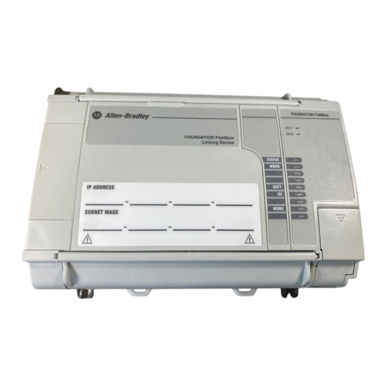
Page 6: Parts Illustration Of The Fieldbus Linking Device
Parts Illustration of the Fieldbus Linking Device The sample illustration shows the parts that comprise the 1757-FFLD linking OUNDATION device, which links Rockwell Automation products and F Fieldbus products on the Ethernet network to products on H1 links. 31989-M Feature... -
Page 7: Install The Linking Device
Foundation Fieldbus Linking Device 7 Before You Begin The following software is compatible with this revision of the linking device: • RSFieldbus software, version 2.03 or later • RSLogix 5000 programming software, version 16.03 or later • RSLinx Classic software, version 2.52 or later •... - Page 8 8 Foundation Fieldbus Linking Device Product Dimensions Dimension Measurement Height (A) 138 mm (5.43 in.) Width (B) 168 mm (6.62 in.) Depth (C) 87 mm (3.43 in.) 43481 Mount on a DIN Rail The linking device DIN-rail latch locks in the open position so that the linking device can be easily attached to or removed from the DIN rail.
- Page 9 Foundation Fieldbus Linking Device 9 3. While pressing the linking device down against the top of the rail, snap the bottom of the linking device into position. Top Slot Middle of DIN DIN Rail 43482 Dimension Height 138 mm (5.43 in.) 69 mm (2.715 in.) 69 mm (2.715 in.) DIN latch closed, 76.1 mm (3 in.) DIN latch open Mount on a Panel...
- Page 10 10 Foundation Fieldbus Linking Device 2. Use the following figures to mount the linking device to a panel by using #8 or M4 screws tightened to 1.1…1.8 N•m (10…16 lb•in). All dimensions are in mm (in.). (6.62) DIN Rail Center Line (5.19) (4.813) 43580...
-
Page 11: Wire The Linking Device
For further details, see: OUNDATION • the F Fieldbus specifications at http://www.fieldbus.org, publication AG-140 • the Fieldbus Solutions for Rockwell Automation’s Integrated Architecture User Manual, publication 1757-UM006, for a condensed overview of fieldbus wiring considerations. Publication 1757-IN021E-EN-P - August 2009... - Page 12 12 Foundation Fieldbus Linking Device Ethernet Connection If you connect or disconnect the communication cable with power applied to WARNING this module or any device on the network, an electrical arc can occur. This could cause an explosion in hazardous location installations. Be sure that power is removed or the area is nonhazardous before proceeding Connect your Ethernet cable to the Ethernet port on the underside of the linking device.
- Page 13 Foundation Fieldbus Linking Device 13 3. Complete step 1 step 2 for all H1 cables. 4. Insert the RTB into the corresponding socket. H1 Terminal Block Layout (catalog number 1757-FFLD4 shown) H1-1 H1-2 H1-3 H1-4 Power and Grounding You must use a power conditioner between your fieldbus power supply and IMPORTANT the devices on the fieldbus network.
-
Page 14: Configure The Linking Device
The following instructions describe how to configure and set up network parameters for your linking device. Assign an IP Address The Rockwell Automation BOOTP/DHCP Server (BOOTP) is a standalone program that combines the functionality of standard BOOTP software with DHCP software. The linking device is shipped with DHCP enabled. - Page 15 Foundation Fieldbus Linking Device 15 3. Double-click the request. A New Entry dialog box opens. 4. Type the IP address for the linking device. 5. Click OK. The device is added to the Relation List at the bottom of the BOOTP/DHCP Server window.
- Page 16 16 Foundation Fieldbus Linking Device 7. To enable DHCP for the linking device, select the device and click Enable DHCP. Save the Relation List You can save the Relation List for later use. Do these steps to save the Relation List. 1.
- Page 17 Foundation Fieldbus Linking Device 17 Set the Linking Device’s Network Parameters 1. Open RSLinx software and click the RSWho icon. 2. Browse to the linking device under the Ethernet/IP driver. 3. Right-click the linking device and choose Module Configuration to set network parameters.
-
Page 18: Troubleshoot The Linking Device
18 Foundation Fieldbus Linking Device 4. Click the Port Configuration tab to view or change parameters. 5. When you finish making changes, click Apply and then OK. Troubleshoot the Linking Device The following instructions describe how to maintain your linking device. Reset the Linking Device You can reset the linking device with the: •... - Page 19 Foundation Fieldbus Linking Device 19 Reset Configuration The Reset Configuration removes power from the battery, clearing all downloaded fieldbus configurations. The linking device retains its network configuration and web page password information through this reset. Do these steps to reset configuration. 1.
- Page 20 WDOG Normal operation. (watchdog) Flashing red Software fault. Contact Rockwell Automation Technical Support. BATT Normal operation. (battery) Flashing red Jumper is missing (or not seated on the two rightmost pins), or the battery is low or dead.
-
Page 21: Specifications
IP address with another device on your network. If the BATT status indicator remains on after the jumper is replaced, and power has been returned to the linking device, contact Rockwell Automation Technical Support. Specifications 1757-FFLD2, 1757-FFLD4 - Technical Specifications... - Page 22 22 Foundation Fieldbus Linking Device 1757-FFLD2, 1757-FFLD4 - Technical Specifications Attribute Value 2 - on Fieldbus ports Wiring category 3 - on power ports 2 - on Ethernet ports Terminal block torque specifications 0.34 N•m (3 lb•in) on power and Fieldbus wire connections Wire size DC power connection...
- Page 23 Foundation Fieldbus Linking Device 23 1757-FFLD2, 1757-FFLD4 - Environmental Specifications Attribute Value Operating temperature 0…60 °C (32…140 °F) IEC 60068-2-1 (Test Ad, Operating Cold) IEC 60068-2-2 (Test Bd, Operating Dry Heat) IEC 60068-2-14 (Test Nb, Operating Thermal Shock) Nonoperating temperature -40…85 °C (-40…185 °F) IEC 60068-2-1 (Test Ab, Unpackaged Nonoperating Cold)
- Page 24 24 Foundation Fieldbus Linking Device 1757-FFLD2, 1757-FFLD4 - Environmental Specifications Attribute Value Radiated RF immunity 1V/m with 1 kHz sine-wave 80% AM from 2000…2700 MHz IEC 61000-4-3 10V/m with 1 kHz sine-wave 80% AM from 80…2000 MHz 10V/m with 200 Hz 50% Pulse 100% AM at 900 MHz and 1890 MHz EFT/B immunity ±2 kV at 5 kHz on power ports...
- Page 25 Foundation Fieldbus Linking Device 25 1757-FFLD2, 1757-FFLD4 - Certifications Value Certification European Union 2004/108/EC EMC Directive, compliant with: • EN 61326-1; Meas./Control/Lab., Industrial Requirements • EN 61000-6-2; Industrial Immunity • EN 61000-6-4; Industrial Emissions • EN 61131-2; Programmable Controllers (Clause 8, Zone A & B) C-Tick Australian Radiocommunications Act, compliant with:...
-
Page 26: Additional Resources
26 Foundation Fieldbus Linking Device Additional Resources These documents contain additional information concerning related Rockwell Automation products. Resource Description Fieldbus Wiring and Installation Provides information on how to wire, power, OUNDATION Application Guide publication at and configure network components. http://www.fieldbus.org, publication AG-140 Fieldbus Intrinsic Safe Systems... - Page 27 Foundation Fieldbus Linking Device 27 Notes: Publication 1757-IN021E-EN-P - August 2009...
- Page 28 New Product Satisfaction Return Rockwell Automation tests all of its products to ensure that they are fully operational when shipped from the manufacturing facility. However, if your product is not functioning and needs to be returned, follow these procedures.
Need help?
Do you have a question about the Allen-Bradley 1757-FFLD2 and is the answer not in the manual?
Questions and answers