Ampac ZoneSense PLUS Operation & Programming Manual
Fire alarm control panel
Hide thumbs
Also See for ZoneSense PLUS:
- Installation & commissioning (51 pages) ,
- Installation, commissioning & operation (50 pages) ,
- Installation & commissioning (28 pages)

Subscribe to Our Youtube Channel
Related Manuals for Ampac ZoneSense PLUS


Summary of Contents for Ampac ZoneSense PLUS
- Page 1 Fire detection and evacuation solutions that save lives. ZoneSense PLUS Fire Alarm Control Panel EN54 2 & 4 1997 Operation & Programming MAN 2374-11...
- Page 2 MAN 2374 -11 Responding to an Alarm 1. Indicators FIRE ZONE ZONE 1 ZONE 2 SEVEN FIRE FAULT/DISABLED/TEST Common Fire Indicator Zone Fire Indicator First Zone in Alarm. (Steady) (Steady) (Displayed) 2. To Disable External Sounder and / or Sound Evacuation DISABLED ALARMS ...
-
Page 3: Table Of Contents
MAN 2374 -11 Contents Introduction ........................... 5 Purpose........................5 Scope ......................... 5 References ......................... 5 Controls – Front Panel Controls, Indicators & Testing .............. 7 System Controls and Indicators ................... 7 Levels of Access ......................7 Passwords ........................7 System Controls ......................8 Indicators –... - Page 4 MAN 2374 -11 6.3.10 Display ......................27 6.3.11 Zone Labels....................28 6.3.12 EOL (END OF LINE) ..................28 6.3.13 Zone S/C ..................... 28 Appendix A: EN54 Menu Structure ..................29 Status ........................29 Faults ........................30 Test .......................... 30 Disable ........................31 System ........................
-
Page 5: Introduction
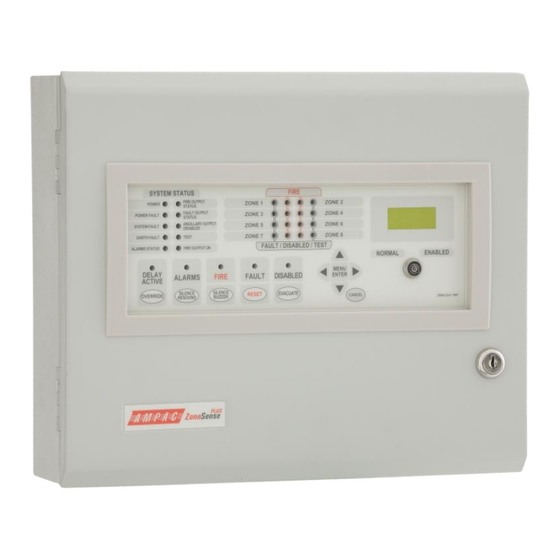
This manual is an instructional tool for the programming / reprogramming and operation of the ZoneSense PLUS Fire Alarm Control Panel (FACP). Using 3 levels of access the ZoneSense PLUS Fire Alarm Control Panel (FACP) is controlled and programmed this through the keypad on the front panel. - Page 6 MAN 2374 -11 Figure 1: Examples of the ABS (BX1) and Metal (BX10) Cabinets...
-
Page 7: Controls - Front Panel Controls, Indicators & Testing
Passwords for level 3 are a fixed 4 digit number (pre-commissioning factory set to 3333). The metal cabinet version of ZoneSense PLUS with an outer front door but no control enable key switch fitted has a link across the key switch terminals. -
Page 8: System Controls
ENABLED Controls, Normal – Enabled (Key Switch) A key switch for controlling system access between levels 1 and 2. All Control Enable key switches fitted to EN54 panels are keyed alike. This key is unique to Ampac. DELAY ACTIVE OVERRIDE Delay Override Used to turn Off the delays to outputs programmed in to the panel. - Page 9 MAN 2374 -11 For the purposes of this explanation the following indicators perform these functions; MENU ENTER Enter or Menu is used to update the program once the MENU control settings have been set and to access the various menus ENTER and sub-menus.
-
Page 10: Indicators - Front Panel
MAN 2374 -11 3 Indicators – Front Panel All indicators are visible at access level one. If flashing indicators are used the on / off periods are >0.25 seconds and the flash frequencies are not less than: 1Hz for Alarm indications 0.2Hz for fault indications. -
Page 11: Common Indicators
MAN 2374 -11 3.2 Common Indicators There are five indicators within the control area of the front panel. DELAY ACTIVE OVERRIDE Delay Active / Override – Amber When one or more zones are programmed with delay this indicator shall be “On” (steady) with the panel in the normal state or with a zone on the panel in alarm which is not programmed with Delay. -
Page 12: Liquid Crystal Display
Alarm, Fault and Isolate information is accessed through the Main Menu. When the FACP is in its normal state a default screen will be displayed. Examples of possible LCD Displays AMPAC F 1/1 AMPAC F 1/2... -
Page 13: Level 1 Access
MAN 2374 -11 4 Level 1 Access Is a read only menu that allows the operator to; ➢ Interrogate the panel to determine the state of selected outputs; STATUS ➢ View any faults that may be present on the FACP. FAULTS ... -
Page 14: Sounders
MAN 2374 -11 4.1.2 Sounders Press Enter then Move Left or Move Right to select the required Sounder (1 – 8). OR press Move right to access Voltage. The LCD readout will indicate if the Sounder is; SOUNDER 8 SOUNDER 2 SOUNDER 7... -
Page 15: Faults
MAN 2374 -11 4.2 Faults Pressing Enter will display all faults in a sequential order. If there is more than one fault on the system the operator can scroll through each fault by using the Move Left and Right keys. -
Page 16: Level 2 Access
MAN 2374 -11 5 Level 2 Access At this level the operator is expected to have under gone training so as to be able to; ➢ Test crucial elements of the system and; TEST ➢ Disable dedicated facilities that may be in fault. DISABLE ... -
Page 17: Walk Test
MAN 2374 -11 5.1.2 Walk Test IMPORTANT: The Brigade, Agent Release and any other system specific signalling should be DISABLED prior to initiating this test. A Walk Test, sets the Zone to Non latching and allows the technician to test detectors and MCP’s on that Zone. -
Page 18: Disables
MAN 2374 -11 5.2 Disables To display the number of Disables press Enter to access the menus then Move Left or Move Right to select the required menu. The number of Disable will be displayed. Zone Outputs Relay Sounder Zones 1 to 8 are Relays 1 to 8 are... -
Page 19: Level 3 Access Programming
MAN 2374 -11 6 Level 3 Access Programming Level 3 is a technical level that allows a technician to; ➢ Initialise the FACP so it is capable of recognising how the system is constructed; and SYSTEM ➢ Program how it will present information as well as how it will react to a change of state of an input and / or output. -
Page 20: System
MAN 2374 -11 6.2 System After entering the Level 3 Password and moving to the SYSTEM menu press Enter and the; 1. Zone DISABLED LED’s will illuminate; Common DISABLED LED will flash; and the LCD will display; BUZZER SYSTEM DISABLED SYSTEM DISABLED And then BUZZER... -
Page 21: Mimic
MAN 2374 -11 6.2.2 Mimic This tells the FACP how many Zone Mimic Indicator Boards are on the system hence how many to look for. Set the number by using the Move Down and / or Move Up keys to increment to the desired number (maximum of 8). -
Page 22: Zones
MAN 2374 -11 6.3.1 Zones Press Enter and the Zones Menu will be displayed on the LCD screen. Pressing Enter again will access the Zones sub menu where first the Move Right and Move Left keys are used to select ... -
Page 23: Clock
MAN 2374 -11 6.3.3 Clock To set the day and time press Enter and the day will be highlighted. Use the Move Up or Move Down keys to step through the days of the week, then the Move Right key to access the ... -
Page 24: Relays
MAN 2374 -11 6.3.5 Relays Press Enter then use the Move Right and / or Move Left keys to select a relay that will be operated by the selected functions in the sub - menu . Press Enter to access the sub – menu then ... -
Page 25: Fire Fan
MAN 2374 -11 6.3.6 Fire Fan The sub menu consists off; Alarm Inhibit Function For: Alarm Inhibit FAN 2 Press Enter then use the Move Right and / or Move Left keys to select the Fire Fan that will be controlled by the selected functions in the sub - menu . -
Page 26: Agent
MAN 2374 -11 6.3.7 Agent If Yes was selected in the SYSTEM menu the Sub – Menu seen below will be available. Press Enter to access the sub-menu. The sub-menu consists off; Release Press Sw Auto Delay Man Delay No LCP’s Solenoid Pyrogen Metron... -
Page 27: Sounders
Move Up and the Move Down keys to move through the alphabet. A maximum of 16 characters are available for this message. AMPAC < INFO > Press Enter to update each Program and Cancel to back out of the Menu. -
Page 28: Zone Labels
MAN 2374 -11 6.3.11 Zone Labels To name the Zones press Enter then the Move Right and / or the Move Left keys to select a Zone. Press Enter and use the Move left and / or Move Right keys to move the cursor through ... -
Page 29: Appendix A: En54 Menu Structure
MAN 2374 -11 7 Appendix A: EN54 Menu Structure 7.1 Status PRESS THESE KEYS LEGEND: PRESS CANCEL AT MENU PRESS ENTER TO SET YES / NO, OFF / ON, CANCEL ANY TIME TO BACK ENTER STATUS OFF NORMAL OUT OF THE MENU MENU ENTER PRESS: MOVE FORWARD... -
Page 30: Faults
MAN 2374 -11 7.2 Faults PRESS CANCEL AT ANY TIME TO BACK MENU CANCEL LEGEND: PRESS ENTER TO GO TO MENU OUT OF THE MENU OR STOP TEST ENTER FAULTS MENU ENTER PRESS TO VIEW DETAILS OF EACH FAULT MENU CANCEL ENTER FAULTS... -
Page 31: Disable
MAN 2374 -11 7.4 Disable MENU CANCEL PRESS CANCEL AT ANY TIME TO BACK OUT OF THE MENU LEGEND: PRESS ENTER TO ACCESS MENU ENTER DISABLE MENU ENTER PRESS MOVE FORWARD / BACKWARD THROUGH THE MENU MENU CANCEL ENTER PRESS TO MAKE ACTIVE PRESS TO DISABLE ZONE 2 ZONE 1... -
Page 32: System
MAN 2374 -11 7.5 System ENTER ALARM RESOUND MENU MENU MENU SYSTEM BUZZER PASSWORD ENTER ENTER ENTER YES / NO YES / NO FACTORY DEFAULT EXAMPLE PASSWORD IS 3333 SET RESOUND TO YES THEN MOVE TO ALARM EXAMPLE OF Y E S EARTH MON SETTING YES / NO... -
Page 33: Program
MAN 2374 -11 7.6 Program Note: Any Zone may be allocated to be a trigger zone. Select the Zone (1 to 8 ) to initiate the release of the agent. PROGRAM If zones have already been allocated to change the zone first remove the allocation of the current zone and press ENTER to update the program then, reallocate the new zone and MENU... -
Page 34: Appendix B: Simple Example Wiring Diagram Of A Basic Facp
MAN 2374 -11 8 Appendix B: Simple Example Wiring Diagram of a Basic FACP... -
Page 35: Appendix C: En54 Abs Inner Front Panel Configuration Labelling
MAN 2374 -11 9 Appendix C: EN54 ABS Inner Front Panel Configuration Labelling WARN SOUNDER SOUNDER SOUNDER SOUNDER SOUNDER SOUNDER SOUNDER SOUNDER ZONE CONFIGURATION BELL ALARM B ALARM 1 B ALARM 2 RELAY 1 RELAY 2 RELAY 3 RELAY 4 RELAY 5 RELAY 6 RELAY 7 RELAY 8 FAN 1 FAN 2 FAN 3... - Page 36 MAN 2374 -11 UNCONTROLLED DOCUMENT NOTE: Due to AMPAC’s commitment to continuous improvement specifications may change without notice...
Need help?
Do you have a question about the ZoneSense PLUS and is the answer not in the manual?
Questions and answers