Ampac ZoneSense PLUS Installation, Commissioning & Operation
Fire alarm control panel
Hide thumbs
Also See for ZoneSense PLUS:
- Installation & commissioning (51 pages) ,
- Installation, commissioning & operation (50 pages) ,
- Operation & programming manual (36 pages)

Related Manuals for Ampac ZoneSense PLUS


Summary of Contents for Ampac ZoneSense PLUS
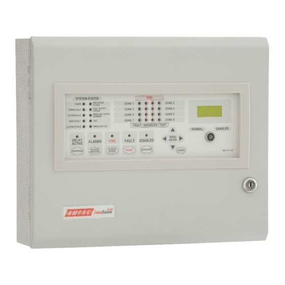
- Page 1 Fire detection and evacuation solutions that save lives. ZoneSense PLUS Fire Alarm Control Panel EN54 2 & 4 1997 Installation, Commissioning & Operation Add On’s MAN 2512-5...
-
Page 2: Table Of Contents
MAN 2512-5 Contents About This Manual ........................ 3 Introduction ....................... 3 General Requirements ....................3 References ......................... 3 Symbols ........................3 PCB Removal / Replacement ..................4 Wiring to the Main Card BRD25MCB ..................5 Communications ......................5 Adding Control and Monitoring Facilities ................6 Internal Communications Connector (RS485) ............. -
Page 3: About This Manual
This manual is an instructional tool for the installation and commissioning, of add on ancillary cards, modules and boards that can be fitted to the ZoneSense PLUS Fire Alarm Control Panel (FACP) and should be read in conjunction with the main Installation and Commissioning Manual. -
Page 4: Pcb Removal / Replacement
MAN 2512-5 PCB Removal / Replacement If the PCB’s have to be removed the following precautions should be observed; 1. Removing the door will provide better access to the boards and ensure the hinges are not accidentally stressed. 2. Personal anti- static procedures must be followed. 3. -
Page 5: Wiring To The Main Card Brd25Mcb
MAN 2512-5 Wiring to the Main Card BRD25MCB Communications External Communications Terminals (RS485) TB2 1, 2 & 3 The RS 485 output drives the remote cards and mimics up to a distance of 1.2km from the panel itself. The external cabling (2x2 shielded pair plus power) is wired to TB2 +, - and earth. ... -
Page 6: Adding Control And Monitoring Facilities
MAN 2512-5 Adding Control and Monitoring Facilities A combination of one of each type of board / card, but not all of them, can be mounted on the back pan or the front panel of the FACP to provide additional features to a standard panel. All board inputs or outputs are programmable to any combination of zones. -
Page 7: Installation And Wiring Of Add-On Cards And Boards
Address Setting and Terminating the Communication Bus Address Setting (SW1) Except for the LED Mimics in ZoneSense PLUS FACP’s there can only be one (1) Board / Card of each type so the address on each board is set to 1. - Page 8 MAN 2512-5 Terminating the Communication Bus LK1 is the EOL Link and must be inserted on the last board on each communications bus. If not, a communications fault can occur. Front Panel Front Panel INSERT RS485 ( Link 1 in Table below ) Card 1 Card 2 BUS 1 ( B1 )
-
Page 9: Input Board Brd25Sipb
TB 2 – 9 Taking note of the Common 0v terminals connect the voltage free contacts as shown below. Note: only the first 8 are functionally programmable in ZoneSense PLUS There can only be 1 Input Board so the address on each board is set to 1. -
Page 10: Relay Board Brd25Ewrb
MAN 2512-5 Relay Board BRD25EWRB Relay Board (Internal) BRD25EWRB -A The Relay Board has provision for 8 X 1 Amp voltage free change over contacts for control or monitoring purposes. Communication and control cabling is the same as all other internal boards. Quiescent Current: 2.4mA O/P 1 O/P 2... -
Page 11: Fire Fan Module Brd25Fcb
MAN 2512-5 Fire Fan Module BRD25FCB The Fire Fan Module has four ( 4 ) separate fan controls each having an On, Auto and Off function switch and a set of three (3) monitoring LED’s. The LED’s indicate the status of the equipment eg. Run, Fault or Stop. -
Page 12: Fan Termination Board
MAN 2512-5 Fan Termination Board The Fan Termination Board interfaces between the Fire Fan Module and the plant/equipment it controls via the 24 volt 250mA Start, Stop, current limited, relay outputs and monitor inputs. Programmable monitoring of the field equipment is achieved using 0 volts as an input level to indicate run, fault and stop conditions of that equipment. -
Page 13: General Indicator Card Brd25Gib-A
MAN 2512-5 General Indicator Card BRD25GIB-A Note: The Cards BRD25GIB –A, B, C and D all have a common PCB. What sets them apart from each other is not only the function they perform but how the componentry is loaded onto the card to perform that function. -
Page 14: Switch And Indicator Card Brd25Gib-B
MAN 2512-5 Switch and Indicator Card BRD25GIB-B This Card can effectively perform 2 different functions. Firstly the indicators monitor the first 8 inputs of the 16 Way Input Termination Board while secondly the switches can be programmed to manually operate a specific relay in the system. Quiescent Current: 3.6mA Card &... -
Page 15: Led Annunciator Master (Lam) Brd25Gib-E
MAN 2512-5 LED Annunciator Master (LAM) BRD25GIB-E The LAM provides remote stand alone FACP status, Alarm and Fault / Isolate Indication of 8 zones. Two push buttons, Lamp Test and Silence Buzzer, provide for local testing of the indicators and buzzer while the buzzer duplicates that at the FACP. - Page 16 MAN 2512-5 Indicators There are twenty four active indicators on the front panel of the LAM. Flashing indicators are used, the on / off periods are not less than 0.25 seconds and the flash frequencies are not less than: 1Hz for alarm indications ( 0.5 second on, 0.5 second off ) 0.5Hz for fault indications ( 1 second on and 1 second off ) FIRE Red The common Alarm indicator will be flashing when an alarm condition is...
- Page 17 MAN 2512-5 equipment. A fault can be no mains, high charger voltage, no charger voltage, low battery voltage or missing (or damaged) battery. FAULT / DISABLED FIRE Zone Indicators There are two indicators for each of the eight zones. Zone Fire– Red (x8) Each indicator will show if the individual zone it represents is in the fire condition (flashing at the alarm rate and then steady when the acknowledge control has been operated at the FACP).
-
Page 18: Sounder Board Brd25Sopb-A
MAN 2512-5 Sounder Board BRD25SOPB-A The Sounder Board expands the number of sounders that can be used on an FACP to 8. Each solid state output is rated at 24VDC / 500mA. and requires a 10K End of Line (EOL) resistor regardless whether or not a sounder is wired to the circuit. -
Page 19: Appendix A: Adding To The System Menu & Programming
MAN 2512-5 Appendix A: Adding to the System Menu & Programming In this example 1 Input Board, 1 Relay Board and 1 Sounder Board will be added to the system. The Display and Zone Labels will then be edited. Step 1: Go to the SYSTEM MENU and then follow the procedure as set out below. - Page 20 MAN 2512-5 Step 2 LEGEND: PROGRAM MENU ENTER MENU ENTER CANCEL PRESS CANCEL AT ANY TIME TO BACK OUT OF THE MENU CANCEL ZONES MENU PRESS ENTER TO GO TO SUB MENU, SET MENU OR UPDATE PROGRAM ENTER PRESS MOVE FORWARD / BACKWARD THROUGH THE MENU PRESS MOVE FORWARD THROUGH THE MENU CLOCK MCP ZONE...
-
Page 21: Appendix B:status And Programming Screens
MAN 2512-5 Appendix B:Status and Programming Screens The following shows all the screens that are possible in the FACP and how to navigate through them. I f a screen is not available it means that option has not been installed or is not available to the model in use. -
Page 22: Level 3 System Programming
MAN 2512-5 Level 3 System Programming ENT ER MENU ALARM RESOUND MENU MENU SYSTEM BUZZER ENTER PASSWORD ENTER ENTER YES / NO YES / NO FACTORY DEFAULT EXAMPLE PASSWORD IS 3333 SET RESOUND TO YES THEN MOVE TO ALARM EXAMPLE OF Y E S EARTH MON SETTING... -
Page 23: Level 3 Programming Menu
MAN 2512-5 Level 3 Programming Menu PROGRAM MENU ENTER SELECT DOUBLE MENU Z ONES NON LATCH AGENT T1 AGENT T2 ZONE 1 - 8 KNOCK ENTER NORMAL 1 TO 8 LEGEND: MENU PRESS ACF TO ISOLATE CIRCUITS EXTERNAL TO FACP SELECT SELECT ASSIGN MCP... - Page 24 MAN 2512-5 UNCONTROLLED DOCUMENT NOTE: Due to AMPAC’s commitment to continuous improvement specifications may change without notice.
Need help?
Do you have a question about the ZoneSense PLUS and is the answer not in the manual?
Questions and answers