Table of Contents
Advertisement
Quick Links
Advertisement
Table of Contents

Related Manuals for IBM 8038


Summary of Contents for IBM 8038
- Page 1 BladeCenter HS23E Type 8038 and 8039 Installation and User's Guide...
- Page 3 BladeCenter HS23E Type 8038 and 8039 Installation and User's Guide...
- Page 4 Before using this information and the product it supports, read the general information in “Notices” on page 77, the Warranty Information document, and the IBM Safety Information and the Environmental Notices and User Guide documents on the IBM Documentation CD.
-
Page 5: Table Of Contents
. 63 Instructions for IBM Business Partners . . 18 Configuring the LAN over USB interface How to send DSA data to IBM . . 19 manually . . 64 Removing the blade server from the BladeCenter unit . - Page 6 Index ....85 d'Industrie Canada . . 81 Australia and New Zealand Class A statement . 81 European Union EMC Directive conformance statement . . 81 BladeCenter HS23E Type 8038 and 8039: Installation and User's Guide...
-
Page 7: Safety
Ennen kuin asennat tämän tuotteen, lue turvaohjeet kohdasta Safety Information. Avant d'installer ce produit, lisez les consignes de sécurité. Vor der Installation dieses Produkts die Sicherheitshinweise lesen. Prima di installare questo prodotto, leggere le Informazioni sulla Sicurezza. © Copyright IBM Corp. 2012, 2013... -
Page 8: Safety Statements
Safety Information document. For example, if a caution statement is labeled “Statement 1,” translations for that caution statement are in the Safety Information document under “Statement 1.” BladeCenter HS23E Type 8038 and 8039: Installation and User's Guide... - Page 9 Be sure to read all caution and danger statements in this documentation before you perform the procedures. Read any additional safety information that comes with your system or optional device before you install the device. Statement 1 DANGER Electrical current from power, telephone, and communication cables is hazardous.
- Page 10 Note the following. Laser radiation when open. Do not stare into the beam, do not view directly with optical instruments, and avoid direct exposure to the beam. Statement 4 viii BladeCenter HS23E Type 8038 and 8039: Installation and User's Guide...
- Page 11 ≥ 18 kg (39.7 lb) ≥ 32 kg (70.5 lb) ≥ 55 kg (121.2 lb) CAUTION: Use safe practices when lifting. Statement 8 CAUTION: Never remove the cover on a power supply or any part that has the following label attached. Hazardous voltage, current, and energy levels are present inside any component that has this label attached.
- Page 12 The device also might have more than one power cord. To remove all electrical current from the device, ensure that all power cords are disconnected from the power source. BladeCenter HS23E Type 8038 and 8039: Installation and User's Guide...
- Page 13 Rack Safety Information, Statement 2 DANGER v Always lower the leveling pads on the rack cabinet. v Always install stabilizer brackets on the rack cabinet. v Always install servers and optional devices starting from the bottom of the rack cabinet. v Always install the heaviest devices in the bottom of the rack cabinet.
- Page 14 BladeCenter HS23E Type 8038 and 8039: Installation and User's Guide...
-
Page 15: Chapter 1. Introduction
Chapter 1. Introduction The IBM BladeCenter HS23E Type 8038 and 8039 blade server is compatible with ® IBM BladeCenter units. This high density, high performance, single-wide blade server is ideally suited for medium and large businesses. The IBM BladeCenter HS23E blade server supports up to two multi-core Intel Xeon microprocessors and... - Page 16 A set of blank labels for your blade server comes with the BladeCenter unit. When you install the blade server in the BladeCenter unit, write identifying information BladeCenter HS23E Type 8038 and 8039: Installation and User's Guide...
-
Page 17: Related Documentation
Integrated Management Module II User's Guide This document explains how to use the functions of the IMM2 that is installed in an IBM server. The IMM2 works with IBM UEFI firmware to provide ® systems-management capability for System x servers and blade servers. -
Page 18: The Ibm Documentation Cd
The IBM Documentation CD contains documentation for your blade server in Portable Document Format (PDF) and includes the IBM Documentation Browser to help you find information quickly. You can run the IBM Documentation CD on any computer that meets the hardware and software requirements. Hardware and software requirements Use this information to determine the minimum hardware and software requirements for the blade server. -
Page 19: Notices And Statements In This Document
The caution and danger statements in this document are also in the multilingual Safety Information document, which is on the IBM Documentation CD. Each statement is numbered for reference to the corresponding statement in the Safety Information document. -
Page 20: What Your Blade Server Offers
Integrated Management Module II (IMM2) The integrated management module II (IMM2) combines service processor functions, video controller, the remote presence, and blue-screen capture features in a single chip. The IMM2 provides advanced service-processor control, BladeCenter HS23E Type 8038 and 8039: Installation and User's Guide... - Page 21 By using industry standards, IBM Systems Director supports multiple operating systems and virtualization technologies for IBM and non-IBM x86 platforms. For more information, see “IBM Systems Director” on page 9.
-
Page 22: Reliability, Availability, And Serviceability Features
Customer support center 24 hours per day, 7 days a week 1. Service availability will vary by country. Response time will vary depending on the number and nature of incoming calls. BladeCenter HS23E Type 8038 and 8039: Installation and User's Guide... -
Page 23: Ibm Systems Director
A set of common tasks that are included with IBM Systems Director provides many of the core capabilities that are required for basic management, which means instant out-of-the-box business value. -
Page 24: Major Components Of The Blade Server
Updating installed plug-ins to add new features and functions to the base capabilities v Managing the life cycles of virtual resources For more information about IBM Systems Director, see the documentation at http://publib.boulder.ibm.com/infocenter/eserver/v1r2/topic/diricinfo_all/ diricinfoparent.html or http://www.ibm.com/servers/eserver/xseries/ systems_management/, which presents an overview of IBM Systems Management and IBM Systems Director. -
Page 25: Chapter 2. Power, Controls, And Indicators
Advanced-Management-Module Web interface or through IBM Director Console. For more information about the Advanced-Management-Module Web interface, see ® http://www.ibm.com/systems/management/. For more information about IBM ® Director, see the documentation on the IBM Director CD that comes with the © Copyright IBM Corp. 2012, 2013... - Page 26 If there is no response when you press the KVM select button, you can use the Advanced-Management-Module web interface to determine whether local control has been disabled on the blade server. See http://www.ibm.com/systems/ management/ for more information. Notes: BladeCenter HS23E Type 8038 and 8039: Installation and User's Guide...
- Page 27 1. The operating system in the blade server must provide USB support for the blade server to recognize and use the keyboard and mouse, even if the keyboard and mouse have PS/2-style connectors. 2. If you install a supported Microsoft Windows operating system on the blade server while it is not the current owner of the keyboard, video, and mouse, a delay of up to 1 minute occurs the first time that you switch the keyboard, video, and mouse to the blade server.
-
Page 28: Turning On The Blade Server
The management module can turn off the blade server through the Advanced-Management-Module web interface. For additional information, see the IBM BladeCenter Management Module User's Guide or go to http://www.ibm.com/systems/management/ for more information. BladeCenter HS23E Type 8038 and 8039: Installation and User's Guide... -
Page 29: Blade Server Connectors
Blade server connectors Use this information to locate blade server system-board components and connectors for optional devices. The following illustration shows the system-board components, including connectors for user-installable optional devices, in the blade server. BladeCenter GPU expansion unit LED The following illustration identifies the fault LED on the front of the BladeCenter GPU expansion (BGE) unit. - Page 30 BladeCenter HS23E Type 8038 and 8039: Installation and User's Guide...
-
Page 31: Chapter 3. Installing Options
To ensure proper cooling, do not operate the BladeCenter unit without a blade server, expansion unit, or blade filler installed in each blade-server bay. See the documentation for your BladeCenter unit for additional information. © Copyright IBM Corp. 2012, 2013... -
Page 32: Handling Static-Sensitive Devices
IBM Business Partners must also complete the following steps: 1. Before you configure a server for a customer, complete the Solution Assurance checklist at http://w3.ibm.com/support/assure/assur30i.nsf/webindex/ sa294/. BladeCenter HS23E Type 8038 and 8039: Installation and User's Guide... -
Page 33: How To Send Dsa Data To Ibm
3. Shut down and restart the server multiple times to ensure that the server is correctly configured and functions correctly with the newly installed devices. 4. Save the DSA log as a file and send it to IBM. For information about transferring data and logs, see http://publib.boulder.ibm.com/infocenter/ toolsctr/v1r0/index.jsp?topic=/dsa/dsa_main.html. -
Page 34: Removing The Blade Server Cover
5. Place either a blade filler or another blade server in the blade server bay within 1 minute. Removing the blade server cover Use these instructions to open the blade server cover. The following illustration shows how to open the cover on the blade server. BladeCenter HS23E Type 8038 and 8039: Installation and User's Guide... -
Page 35: Installing An Optional Expansion Unit
To open the blade server cover, complete the following steps: 1. Before you begin, read “Safety” on page v and “Installation guidelines” on page 17. 2. If the blade server is installed in a BladeCenter unit, remove it (see “Removing the blade server from the BladeCenter unit”... - Page 36 10. Follow the instructions provided with the expansion unit to install an option in the expansion unit. 11. If you have other devices to install or remove, do so now; otherwise, go to “Completing the installation” on page 43. BladeCenter HS23E Type 8038 and 8039: Installation and User's Guide...
-
Page 37: Removing An Optional Expansion Unit
Removing an optional expansion unit Use these instructions to remove the optional expansion unit from the blade server. To remove an optional expansion unit, complete the following steps: 1. Before you begin, read “Safety” on page v and “Installation guidelines” on page 17. -
Page 38: Removing A Hot-Swap Storage Drive
Use this information to remove a hot-swap storage drive. The blade server has two hot-swap storage bays for installing or removing hot-swap storage devices. To remove a hot-swap hard disk drive or drive filler, complete the following steps. BladeCenter HS23E Type 8038 and 8039: Installation and User's Guide... -
Page 39: Installing A Memory Module
CPU throttling may occur within the BladeCenter E's ambient air temperature specification range if these limitations are not followed as below: v DIMM: – IBM option part number 90Y3221 (CRU part number 90Y3223) - 16 GB 4R x 4 1066 MHz VLP RDIMM 1.35V. v Limitation: –... - Page 40 For rank sparing mode memory installation order on a blade server with quad-rank DIMMs, see Table 3. The following tables show the order that single-rank or dual-rank DIMMs are installed to use rank sparing mode: BladeCenter HS23E Type 8038 and 8039: Installation and User's Guide...
- Page 41 Table 4. Rank sparing mode DIMM installation sequence for single-rank or dual-rank DIMMs (one microprocessor) DIMM pair DIMM connector First 5, 6 Second 3, 4 Third 1, 2 Table 5. Rank sparing mode DIMM installation sequence for single-rank or dual-rank DIMMs (two microprocessors) DIMM pair DIMM connector...
- Page 42 Make sure that the small tabs on the retaining clips are in the notches on the DIMM. If there is a gap between the DIMM and the retaining clips, the DIMM has not been correctly installed. Press the DIMM firmly into the BladeCenter HS23E Type 8038 and 8039: Installation and User's Guide...
-
Page 43: Removing A Memory Module
connector, and then press the retaining clips toward the DIMM until the tabs are fully seated. When the DIMM is correctly installed, the retaining clips are parallel to the sides of the DIMM. 11. If the DIMM access door is open, use your fingers to close it. 12. -
Page 44: Installing A Microprocessor And Heat Sink
2 filler shows that microprocessor socket 2 is not supported. The following illustration shows how to install a microprocessor and heat sink in the blade server. BladeCenter HS23E Type 8038 and 8039: Installation and User's Guide... - Page 45 Attention: 1. Do not use any tools or sharp objects to lift the release levers on the microprocessor socket. Doing so might result in permanent damage to the system board. 2. Do not touch the contacts in the microprocessor socket. Touching these contacts might result in permanent damage to the system board.
- Page 46 Twist the handle on the microprocessor tool counterclockwise to insert the microprocessor into the socket. The microprocessor is keyed to ensure that the microprocessor is installed correctly. The microprocessor rests flush on the socket only if properly installed. BladeCenter HS23E Type 8038 and 8039: Installation and User's Guide...
- Page 47 Attention: v Do not press the microprocessor into the socket. v Do not touch exposed pins of the microprocessor socket. v Make sure that the microprocessor is oriented and aligned correctly in the socket before you try to close the microprocessor retainer. v Do not touch the thermal grease on the bottom of the heat sink or on top of the microprocessor.
-
Page 48: Thermal Grease
15. If you have other devices to install or remove, do so now; otherwise, go to “Completing the installation” on page 43. Thermal grease Use this information to determine the guidelines for using thermal grease on a heat sink and processor. BladeCenter HS23E Type 8038 and 8039: Installation and User's Guide... - Page 49 The thermal grease must be replaced whenever the heat sink has been removed from the top of the microprocessor and is going to be reused or when debris is found in the grease. To replace damaged or contaminated thermal grease on the microprocessor and heat sink, complete the following steps: 1.
-
Page 50: Installing A Usb Flash Key
(see “Installing a CIOv-form-factor expansion card” on page 40). 13. If you have other devices to install or remove, do so now; otherwise, go to “Completing the installation” on page 43. BladeCenter HS23E Type 8038 and 8039: Installation and User's Guide... -
Page 51: I/O Expansion Cards
(CFFh) expansion cards and the other connector supports vertical-combination-I/O (CIOv) expansion cards. See http://www.ibm.com/systems/info/x86servers/serverproven/compat/us/ for a list of available I/O expansion cards for your blade server. Make sure that the BladeCenter unit and the I/O modules to which the I/O expansion card is mapped support the network-interface type of the I/O expansion card. -
Page 52: Installing A Horizontal-Compact-Form-Factor Expansion Card
4. Remove the blade server cover (see “Removing the blade server cover” on page 20). 5. If an optional expansion unit is installed, remove the expansion unit (see “Removing an optional expansion unit” on page 23). BladeCenter HS23E Type 8038 and 8039: Installation and User's Guide... -
Page 53: Removing A Ciov-Form-Factor Expansion Card
6. Locate the blade server expansion connector (see “Blade server connectors” on page 15). 7. If a cover is installed on the expansion connector, remove it by using your fingers to lift the cover from the expansion connector. 8. Touch the static-protective package that contains the expansion card to any unpainted metal surface on the BladeCenter unit or any unpainted metal surface on any other grounded rack component;... -
Page 54: Installing A Ciov-Form-Factor Expansion Card
System Settings and Devices and I/O Ports. To install a CIOv expansion card, complete the following steps: 1. Before you begin, read “Safety” on page v and “Installation guidelines” on page 17. BladeCenter HS23E Type 8038 and 8039: Installation and User's Guide... -
Page 55: Removing A Storage Interface Card
2. If the blade server is installed in a BladeCenter unit, remove it (see “Removing the blade server from the BladeCenter unit” on page 19 for instructions). 3. Carefully lay the blade server on a flat, static-protective surface. 4. Remove the blade server cover (see “Removing the blade server cover” on page 20). -
Page 56: Installing A Storage Interface Card
ServeRAID H1135 controller into the CIOv expansion connector of the blade server. The illustrations and installation instructions are similar for other CIOv storage interface cards. BladeCenter HS23E Type 8038 and 8039: Installation and User's Guide... -
Page 57: Completing The Installation
To install a storage interface card, complete the following steps: 1. Before you begin, read “Safety” on page v and “Installation guidelines” on page 17. 2. If the blade server is installed in a BladeCenter unit, remove it (see “Removing the blade server from the BladeCenter unit”... -
Page 58: Installing The Blade Server Cover
Before you close the cover, make sure that all components are installed and seated correctly and that you have not left loose tools or parts inside the blade server. BladeCenter HS23E Type 8038 and 8039: Installation and User's Guide... -
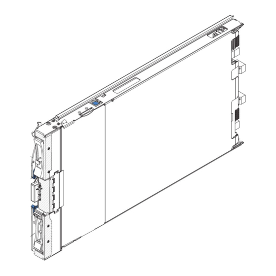
Page 59: Installing The Blade Server In A Bladecenter Unit
5. Pivot the cover to the closed position, as shown in the illustration, until it clicks into place. Press down the cover to make sure the cover is installed securely. Installing the blade server in a BladeCenter unit Use these instructions to install the blade server in a BladeCenter unit. The following illustration shows how to install a blade server into a BladeCenter unit. - Page 60 Setup utility and install the blade server operating system. See “Updating the blade server configuration” on page 47 and Chapter 5, “Installing the operating system,” on page 67 for details. BladeCenter HS23E Type 8038 and 8039: Installation and User's Guide...
-
Page 61: Updating The Blade Server Configuration
If you have changed the configuration of the blade server or if you are installing a different blade server from the one that you removed, you must configure the blade server through the Setup utility, and you might have to install the blade server operating system. - Page 62 BladeCenter HS23E Type 8038 and 8039: Installation and User's Guide...
-
Page 63: Copyright Ibm Corp. 2012, 2013
59 for more information. v IBM FastSetup IBM FastSetup is a no-cost software tool that helps simplify the maintenance and deployment of selected IBM BladeCenter chassis, servers, and components. The intuitive graphical interface initializes all phases of server setup, including discovery, update, and configuration. -
Page 64: Using The Setup Utility
KVM select button on the blade server (see “Blade server controls and LEDs” on page 11 for information). v If you are managing the blade server from a remote location, see the IBM BladeCenter Management Module User's Guide, IBM BladeCenter Management Module Command-Line Interface Reference Guide, or IBM BladeCenter Serial over LAN Setup Guide for information and instructions. - Page 65 Note: Before you configure a UEFI-compatible device, you should update the firmware for your blade server. See “Updating firmware and device drivers” on page 57 for information about how to update the firmware for your blade server. To configure a UEFI-compatible expansion adapter, complete the following steps: 1.
- Page 66 Select this choice to view or enable the POST watchdog timer. v POST Watchdog Timer Value Select this choice to view or set the POST loader watchdog timer value in minutes. v Reboot System on NMI BladeCenter HS23E Type 8038 and 8039: Installation and User's Guide...
- Page 67 Select this choice to enable or disable restarting the system whenever a nonmaskable interrupt (NMI) occurs. Enable is the default. v Halt on Severe Error Select this choice to enable or disable the system from booting into OS, displaying the POST event viewer whenever a severe error was detected. Disable is the default.
-
Page 68: Using Passwords
The ServerGuide program detects the blade server model and optional hardware devices that are installed and uses that information during setup to configure the hardware. The ServerGuide program BladeCenter HS23E Type 8038 and 8039: Installation and User's Guide... -
Page 69: Serverguide Features
When you use the ServerGuide Setup and Installation CD, you do not need setup diskettes. You can use the CD to configure any supported IBM blade server model. The setup program provides a list of tasks that are required to set up the blade server. -
Page 70: Typical Operating-System Installation
To use the Setup utility to configure the boot protocol to boot from a non-UEFI legacy network device for all PXE boot attempts, complete the following steps: 1. Turn on the server (see “Turning on the blade server” on page 14). BladeCenter HS23E Type 8038 and 8039: Installation and User's Guide... -
Page 71: Updating Firmware And Device Drivers
Updating firmware and device drivers IBM periodically makes UEFI code, service processor (IMM) firmware, diagnostic firmware updates, and device driver updates available for the blade server. Provisioning is the set of actions you take to update the firmware and device drivers, and install the operating system. -
Page 72: Configuring Uefi Compatible Devices
® updates from UpdateXpress System Packs, which contain Windows and Linux firmware updates. Typically, use IBM ToolsCenter Bootable Media Creator for the initial set up of a blade server. For more information about the IBM Bootable Media Creator, see http://www.ibm.com/support/entry/portal/docdisplay?lndocid=TOOL-BOMC... -
Page 73: Creating An Array Using The Serveraid H1135 Configuration Utility
However, you must install a device driver to enable the blade server operating system to address the Ethernet controller. For device drivers and information about configuring the Ethernet controller, go to http://www.ibm.com/ supportportal/ . Creating an array using the ServeRAID H1135 configuration utility Use these instructions to create an array using the ServeRAID H1135 configuration utility. -
Page 74: Starting The Lsi Configuration Utility Program
Creating a RAID array of hard disk drives Use this information to create a RAID array of hard disk drives. To create a RAID array of hard disk drives, complete the following steps: BladeCenter HS23E Type 8038 and 8039: Installation and User's Guide... -
Page 75: Creating An Array Using The Serveraid C105 Configuration Utility
6. Press C to create the disk array. 7. Select Apply changes and exit menu to create the array. Note: For more information, see the Installation and User's Guide for ServeRAID H1135 at http://www-947.ibm.com/support/entry/portal/ docdisplay?lndocid=MIGR-5088601&brandind=5000008. Creating an array using the ServeRAID C105 configuration utility Use these instructions to create a software RAID array of hard disk drives. -
Page 76: Setting Option Rom Execution Order
Because the IMM might obtain a random IP address for the LAN over USB interface, the IBM Advanced Settings Utility (ASU) and firmware flash utilities, DSA, and the IBM Director Agent use the Service Location Protocol (SLP) to discover the IMM IP address. These tools perform an SLP multicast discovery on the LAN over USB interface. -
Page 77: Potential Conflicts With The Lan Over Usb Interface
Potential conflicts with the LAN over USB interface In some situations, the IMM LAN over USB interface can conflict with certain network configurations, applications, or both. For example, Open MPI attempts to use all of the available network interfaces on a server. -
Page 78: Configuring The Lan Over Usb Interface Manually
When you install Windows, there will be an unknown RNDIS device in the device manager. IBM provides a Windows INF file that identifies this device. The signed version of the INF is included in all of the Windows versions of the IMM, UEFI, and DSA update packages. - Page 79 Network Adapters. 11. Open a command prompt, type ipconfig, and press Enter. The local area connection for the IBM USB RNDIS appears with an IP address in the range of 169.254.xxx.xxx with a subnet mask set to 255.255.0.0.
- Page 80 BladeCenter HS23E Type 8038 and 8039: Installation and User's Guide...
-
Page 81: Chapter 5. Installing The Operating System
Use this information if you are using RDM to install the blade server operating system. You can use RDM to install a supported operating system on a blade server. Follow the instructions in the documentation that comes with RDM to install a supported operating system. © Copyright IBM Corp. 2012, 2013... -
Page 82: Downloading Installation Instructions
Note: To determine whether an RDM supports an operating system, see http://www.ibm.com/systems/management/ . Downloading installation instructions Use these instructions to download the operating-system installation instructions. To download operating-system installation instructions, go to http:// www.ibm.com/supportportal/ . BladeCenter HS23E Type 8038 and 8039: Installation and User's Guide... -
Page 83: Chapter 6. Solving Problems
BladeCenter unit, and then restart the blade server. If the blade server does not start after you have performed the preceding actions, see the Problem Determination and Service Guide for your blade server on the IBM Documentation CD. Diagnostic tools overview Use this overview to locate specific diagnostic tools to diagnose and solve hardware-related problems. -
Page 84: Serverguide Problems
(UEFI) configuration The diagnostic programs create a merged log that includes events from all collected logs. The information is collected into a file that you can send to IBM service and support. Additionally, you can view the information locally through a generated text report file. - Page 85 Symptom Suggested action The ServerGuide program will Make sure that the operating-system CD is supported by the ServerGuide not start the operating-system program. See the ServerGuide Setup and Installation CD label for a list of supported operating-system versions. The operating system cannot be Make sure that the operating system is supported on the blade server.
- Page 86 BladeCenter HS23E Type 8038 and 8039: Installation and User's Guide...
-
Page 87: Appendix. Getting Help And Technical Assistance
Appendix. Getting help and technical assistance If you need help, service, or technical assistance or just want more information about IBM products, you will find a wide variety of sources available from IBM to assist you. Use this information to obtain additional information about IBM and IBM products, determine what to do if you experience a problem with your IBM system or optional device, and determine whom to call for service, if it is necessary. -
Page 88: Using The Documentation
The troubleshooting information or the diagnostic programs might tell you that you need additional or updated device drivers or other software. IBM maintains pages on the World Wide Web where you can get the latest technical information and download device drivers and updates. -
Page 89: Software Service And Support
Software service and support Through IBM Support Line, you can get telephone assistance, for a fee, with usage, configuration, and software problems with your IBM products. For information about which products are supported by Support Line in your country or region, see http://www.ibm.com/services/supline/products. - Page 90 BladeCenter HS23E Type 8038 and 8039: Installation and User's Guide...
-
Page 91: Notices
Consult your local IBM representative for information on the products and services currently available in your area. Any reference to an IBM product, program, or service is not intended to state or imply that only that IBM product, program, or service may be used. Any functionally equivalent product, program, or service that does not infringe any IBM intellectual property right may be used instead. -
Page 92: Important Notes
“total bytes written” (TBW). A device that has exceeded this limit might fail to respond to system-generated commands or might be incapable of being written to. IBM is not responsible for replacement of a device that has exceeded its maximum guaranteed number of program/erase cycles, as documented in the Official Published Specifications for the device. -
Page 93: Particulate Contamination
IBM makes no representations or warranties with respect to non-IBM products. Support (if any) for the non-IBM products is provided by the third party, not IBM. Some software might differ from its retail version (if available) and might not include user manuals or all program functionality. -
Page 94: Documentation Format
In the request, be sure to include the publication part number and title. When you send information to IBM, you grant IBM a nonexclusive right to use or distribute the information in any way it believes appropriate without incurring any obligation to you. -
Page 95: Industry Canada Class A Emission Compliance Statement
Properly shielded and grounded cables and connectors must be used in order to meet FCC emission limits. IBM is not responsible for any radio or television interference caused by using other than recommended cables and connectors or by unauthorized changes or modifications to this equipment. -
Page 96: Germany Class A Statement
Klasse A ein. Um dieses sicherzustellen, sind die Geräte wie in den Handbüchern beschrieben zu installieren und zu betreiben. Des Weiteren dürfen auch nur von der IBM empfohlene Kabel angeschlossen werden. IBM übernimmt keine Verantwortung für die Einhaltung der Schutzanforderungen, wenn das Produkt ohne Zustimmung der IBM verändert bzw. -
Page 97: Japan Vcci Class A Statement
Japan VCCI Class A statement This is a Class A product based on the standard of the Voluntary Control Council for Interference (VCCI). If this equipment is used in a domestic environment, radio interference may occur, in which case the user may be required to take corrective actions. -
Page 98: Taiwan Class A Compliance Statement
Taiwan Class A compliance statement BladeCenter HS23E Type 8038 and 8039: Installation and User's Guide... -
Page 99: Index
I/O expansion card 37, 38 option, SAS 24 SAS hard disk drive 24 installing 38 DSA, sending data to IBM 74 how to send DSA data to IBM 19 removing 37 completing the blade server installation 43 components illustrated 10... - Page 100 Linux driver 65 modules 25 manual configuration of 64 safety v settings 62 safety statements v, vi Windows driver 64 LAN over USB Linux driver 65 BladeCenter HS23E Type 8038 and 8039: Installation and User's Guide...
- Page 101 50 Light path diagnostics 69 SCSI 24 Problem isolation tables 69 sending diagnostic data to IBM 74 turning off the blade server 14 sending DSA data to IBM 19 turning on the blade server 14 Serial Attached SCSI (SAS)
- Page 102 BladeCenter HS23E Type 8038 and 8039: Installation and User's Guide...
- Page 104 Part Number: 46W8182 Printed in USA (1P) P/N: 46W8182...
Need help?
Do you have a question about the 8038 and is the answer not in the manual?
Questions and answers