Table of Contents
Advertisement
Quick Links
Advertisement
Table of Contents

Related Manuals for Danfoss CS10


Summary of Contents for Danfoss CS10
- Page 1 Technical Information PLUS+1® CS10 Wireless Gateway www.danfoss.com...
- Page 2 Technical Information PLUS+1® CS10 Wireless Gateway Revision history Table of revisions Date Changed November 2020 Removed some redundancy 0102 October 2020 First edition 0101 © Danfoss | November 2020 BC356772124151en-000102...
-
Page 3: Table Of Contents
User liability and safety statements OEM responsibility................................... 5 Overview CS10 Wireless gateway...................................6 Default settings....................................6 Specification WiFi..................................6 Document purpose..................................6 Abbreviations.....................................6 Configuration Connecting wirelessly to CS10..............................7 Overview......................................7 Station mode......................................8 Access point..................................... 11 CAN........................................13 M2M........................................14 LEDs........................................15 Programming Nonfunctional specifications..............................16 ®... -
Page 4: Technical Information (Ti)
GUIDE Software User Manual Operation Guide AQ152886483724 ® Comprehensive technical literature is online at www.danfoss.com Technical Information (TI) A TI is comprehensive information for engineering and service personnel to reference. Module product Data Sheet (DS) A module product DS contains summarized information and parameters that are unique to an individual PLUS+1 ®... -
Page 5: User Liability And Safety Statements
User liability and safety statements OEM responsibility The OEM of a machine or vehicle in which Danfoss products are installed has the full responsibility for all consequences that might occur. Danfoss has no responsibility for any consequences, direct or indirect, caused by failures or malfunctions. -
Page 6: Overview
The WiFi functionality offers the possibility to configure and operate wireless networks. There are two operation modes: “Access point” and “Station mode”. In Access point mode other devices connect to the CS10 device; In Station mode the CS10 device is able to connect to a wireless network providing gateway. Document purpose The main purpose of this document is to provide electrical, mechanical, and configuration details of the CS10 Wireless Gateway. -
Page 7: Configuration
M2M functionality there are two connection options: 1. In the peer to peer mode the CS10 must be configured as an access point. A connection to the CS10 needs to be established using the WiFi menu in the operating system of the Service Tool hosting device. -
Page 8: Station Mode
5. Select the appropriate Country code. 6. If DHCP mode is set to "DHCP diabled" adjust the following settings: • IP address and Network mask for the identification of the CS10 device, • Gateway address and Gateway metric for identifying the AP to connect to, •... - Page 9 PLUS+1® CS10 Wireless Gateway Configuration On the WiFi Connection page, client status shows the connection status of the CS10 device. Enable/Disable activates/deactivates the WiFi unit of the device, the actual status is indicated by the LED WiFi enabled. When using the Connect button the device tries to connect to the access point defined in the WiFi Connection.
- Page 10 Technical Information PLUS+1® CS10 Wireless Gateway Configuration 10 | © Danfoss | November 2020 BC356772124151en-000102...
-
Page 11: Access Point
Technical Information PLUS+1® CS10 Wireless Gateway Configuration Access point 1. Go to the WiFi Configuration page and set “Access point” as Operation mode 2. If Autoenable is set the automatically enable itself when the device is powered 3. Select SSID and Password for identifying the network 4. - Page 12 Technical Information PLUS+1® CS10 Wireless Gateway Configuration On the WiFi Connection page, the status of the configured access point is shown in the section AP status. Enable/Disable activates/deactivates the Access point unit of the device manually, the actual status is indicated by the LED AP enabled.
-
Page 13: Can
Technical Information PLUS+1® CS10 Wireless Gateway Configuration The CAN section provides the possibility to setup a set of messages to be received. The desired baudrate for the CAN unit needs to be set in the field Baudrate. When the baudrate has changed this setting activates after the next power cycle or by using the DeviceRestart button on the Overview page. -
Page 14: M2M
PLUS+1® CS10 Wireless Gateway Configuration The M2M Bridge establishes a connection that transmits CAN messages between CS10 devices using an existing WiFi-connection between them. The two devices can be connected peer to peer where one device is configured as an Access point, and the other one is configured to station mode (DHCP must be disabled). -
Page 15: Leds
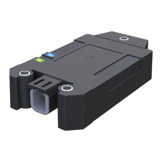
Status. Using the Reset button applies a set of default parameters. LEDs There are four LEDs on every CS10 module: one blue, one white, one green, and one red. These are under application software control of the primary processor. ©... -
Page 16: Programming
Programming Nonfunctional specifications PLUS+1 compliance development ® Applicable company software development standards must be adhered to. At time of initial development Danfoss Power Solutions SW PDP v5.00 (70036901v5.00) is the adopted standard. 16 | © Danfoss | November 2020 BC356772124151en-000102... -
Page 17: Product Ratings
Technical Information PLUS+1® CS10 Wireless Gateway Product ratings Environmental testing criteria Specifications – 30°C to 70°C Operating temperature (ambient) – 40°C to 85°C Storage temperature IP rating (with mating connector attached) IP 67 Caution With DEUTSCH DTM06-6S or equivalent mating connector attached... -
Page 18: Power
Product ratings Power Module supply voltage/maximum current ratings CS10 modules are designed to operate with a nominal 6 to 36 Vdc power supply. The modules will survive with full functionality if the supply voltage remains below 36 Vdc. Specifications Description... -
Page 19: Product Installation And Start-Up
CAN High CAN Shield / Pairing Hot plugging Machine power should be off when connecting CS10 modules to mating connectors. Mounting Care must be taken to insure that the module connector is positioned so that moisture drains away from the connector. -
Page 20: Grounding
Technical Information PLUS+1® CS10 Wireless Gateway Product installation and start-up Grounding Proper operation of any electronic control system requires that all control modules including displays, microcontrollers and expansion modules be connected to a common ground. A dedicated ground wire of appropriate size connected to the machine battery is recommended. -
Page 21: Machine Wiring Guidelines
Technical Information PLUS+1® CS10 Wireless Gateway Product installation and start-up Machine wiring guidelines Warning Unintended movement of the machine or mechanism may cause injury to the technician or bystanders. Improperly protected power input lines against over current conditions may cause damage to the hardware. - Page 22 Phone: +86 21 2080 6201 Danfoss can accept no responsibility for possible errors in catalogues, brochures and other printed material. Danfoss reserves the right to alter its products without notice. This also applies to products already on order provided that such alterations can be made without subsequent changes being necessary in specifications already agreed.
Need help?
Do you have a question about the CS10 and is the answer not in the manual?
Questions and answers