Table of Contents
Advertisement
Advertisement
Table of Contents

Related Manuals for Danfoss AKA 245


Summary of Contents for Danfoss AKA 245
- Page 1 Gateway AKA 245 REFRIGERATION AND Manual AIR CONDITIONING...
-
Page 2: Table Of Contents
Repeat routines for alarm handling ........................37 Data collection takes up this much room .....................38 Terminology ................................39 Menu survey AKA 245 ............................40 Validity This manual is from August 2004, and applies to AKA 245 with software version 6.0x. Manual RS8DT102 © Danfoss 09/2004 AKA 245... -
Page 3: System Survey
System survey Principle Gateway types AKA 245 is a system component to be used in conjunction with controllers in the ADAP-KOOL® series of controls for refrigerating systems. When the gateway is used it is possible to build complex control systems with alarm moni toring and data logging into decentralised refrigerating plant. -
Page 4: Technical Data
(address 125) receives an alarm message of status 1 from a controller). When you use the alarm routing function it is possible to select D02 active or inactive within specifi ed periods of time (cf. section “AKA Alarm Table”). Manual RS8DT102 © Danfoss 09/2004 AKA 245... -
Page 5: Data
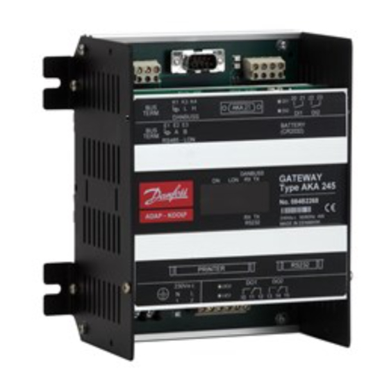
The housing can be screwed into place by means of the screw brackets, or it may be mounted on a DIN rail. When the housing is mounted on a DIN rail, the screw brackets must be broken off . AKA 245 Manual RS8DT102 © Danfoss 09/2004... -
Page 6: Function Overview
9 pol - 9 pol 084B2094 PC and Gateway 9 pol - 25 pol 084B2096 PC and Lantronix MSS 9 pol - 25 pol 084B2098 Lantronix MSS server and Gateway (see fi g. page 10 and 11) Manual RS8DT102 © Danfoss 09/2004 AKA 245... -
Page 7: Connections
Connections Supply voltage 230 V a.c. Max. fuse 10 A AKA 245 must always be provided with earth connection. This is to guarantee safety for persons and noise immunity. DANBUSS Data communication cable Terminals Screen In general, the data communication is connected from controller to controller, so that L is connected to L, and H is connected to H. -
Page 8: Lon
The on/off input DI1 is connected to a pushbutton switch (pulse pressure with spring return). When you push the switch, a signal is sent that the printer is ready and that the paper is correctly placed. Manual RS8DT102 © Danfoss 09/2004 AKA 245... -
Page 9: Manual Change-Over Of Alarm Routing
When a battery is replaced, make sure that the supply voltage is not removed from the gateway. If the bat- tery and supply voltage are both removed at the same time, the clock setup, log setup, collected log data, master control setups and possibly EKC installation data will all be lost. AKA 245 Manual RS8DT102 © Danfoss 09/2004... -
Page 10: Pc, Modem Or Server Connection
In order not to destroy the output on the PC, the modem or the server the following precautions must be taken: - Establish the correct earth connection on AKA 245 - Interrupt the supply voltage to the gateway and to the PC / the Modem / the server, when the cable is mounted and dismounted. - Page 11 Use a standard modem cable. Supply voltage to the modem must be connected, as illustrated (via DO1). This will permit AKA 245 to reset the modem. Also, the modem will be switched on and its start controlled, when AKA 245 is switched on.
-
Page 12: Functional Description
The text will also appear in an alarm message on the printer, e.g.: Transmitter 5:125 System-address: 5:1 LONDON_SOUTH_03 MILK Received: 2000-08-17 14:06:47 Sta tus: 0 Communication OK (DANBUSS) Manual RS8DT102 © Danfoss 09/2004 AKA 245... -
Page 13: Communication Control
All controller alarms will now be transmitted to the master gateway. b) If you select “Auto setup” = “No setup” (the factory setting in AKA 245), the master gateway will not change the setting in the controllers. Chan ges can only be made on each individual AKC controller. - Page 14 Alarms from EKC controllers will also be registered by AKA 245, but if the data connection between the EKC controllers and the gateway is interrupted, only an active alarm, if any, will be present when the connection is reestablished. In other words, all alarms occurring during the period without data com- munication will not be registered.
- Page 15 Alarm list in AKA 245 The alarm list can be displayed from system software type AKM or from control panel type AKA 21. From AKM: via the “History" - "AKA Alarm List” menu. From AKA 21, as follows: - select the master gateway (address = 125) - push key “F1”...
-
Page 16: Aka Alarm Table
It is recommended that only one of the two options be used on the same system. (When AKA 245 is delivered ex stock, the alarm table is not active). Appendix B contains a description of repeat routines for alarm transmissions when calls are not successful. -
Page 17: Printer Function
Alarm printout from PC A printer connected to AKA 245 can print an alarm report from a PC connected to DANBUSS. To use this function, a datagram of a special format has to be transmitted to the gateway. This means that it is in practice the application software in the PC and the internal software in the gateway that use this facility. -
Page 18: Data Collection In Master Gate Way
The master gateway constantly controls all log setups via a simple check-sum calculation. If there is an error, the log in question will be deleted. An alarm will now be given with information about the log number. Manual RS8DT102 © Danfoss 09/2004 AKA 245... -
Page 19: Modem Connection
AKA 245 can act as connecting link between DANBUSS and a modem. (DANFOSS can provide information about other modem types that can be used with the gateway) By connecting the supply to the modem via a relay switch (DO 1) on the gateway, the gateway will be able to reset the modem. -
Page 20: Aka Override Function
AKA override function AKA 245 contains a function capable of reading values from a given function in a given controller on Data communication. The gateway will treat the information and then set the values in other selected controllers in the system. Each individual controller will subsequently carry out the given function. You can max. - Page 21 The procedure is that the gateway constantly makes enquiries with the selected refrigeration appliances following which it transmits signals to the compressor control. AKA 245 Manual RS8DT102 © Danfoss 09/2004...
-
Page 22: Operation
Operation Principle On AKA 245 there are no buttons. The unit is ex clusively operated via control panel type AKA 21 or system software type AKM. Operation from AKA 21 takes place via a menu system coded into the gateway. -
Page 23: Operation Via System Software Type Akm
- receive alarms on the PC - connect a printer to the PC where printouts will be made of all alarms AKA 245 are protected against inadvertent settings and changes of parameters from AKA 21. This is Access limitation done by means of access limi tation dis tributed on three levels: 1) Normal “Daily user level”... -
Page 24: Settings
Reading of whether password is used, and deletion of the use of it, if applicable. System adderess: (and GW type at AKA 245) Setting of the gateways actual DANBUSS system address. An AKA 245 nust be defi ned for either PC gateway, modem gateway or TCP/IP gateway. Communication setup Router: Setup of router tables. -
Page 25: Gateway, Code. Access Display And Access Code
Access to the gateway takes place with control panel AKA 21 in the same way as for other controllers display and access code on DANBUSS. Shown in the AKA 21 display are the units that are connected to DANBUSS. The AKA 245 gate way is symbolised with a “G”. <... -
Page 26: Time Setting
If “Auto” has been selected, settings cannot be made. “Start” Access display for setting the start of the summer time. “Stop” Access display for setting the stop of the summer time. “Month”, “Date”, “Hour”: Setting of time Manual RS8DT102 © Danfoss 09/2004 AKA 245... -
Page 27: Confi Guration
AKM programme version 4 (but may be deleted via AKA 21 without it being known). The password will protect against: - reading of router lines and system confi gurations - setting of router lines and alarm setups AKA 245 Manual RS8DT102 © Danfoss 09/2004... -
Page 28: Address & Gwtype Address And Gateway Type
(The factory-set address in a gateway 125. The address no. 124 is not polled on DANBUSS. The valid address for a AKA 245 will there for be 1 to 123 (not within the LON address range, however) or 125. "Change GW-Type"... -
Page 29: Communication Setup. Setup Of Communication
Selection of port number = 1: Address number of the unit the datagram is to be sent to in the net work is indicated here 2: Address is not set. AKA 245 Manual RS8DT102 © Danfoss 09/2004... - Page 30 “wait for new dial tone” “choose pulse signalling” 7 - 9 “through-call to extension 789” “end of telephone number” c) TCP/IP Setting performed as for modem. Just set an IP address instead of a telephone number. Manual RS8DT102 © Danfoss 09/2004 AKA 245...
- Page 31 When changes have been made in the unit’s communication settings, they have to be stored in the unit’s memory. Activate the “Boot Gateway” function. Now Wait about 30 seconds. The new settings will now be active. AKA 245 Manual RS8DT102 © Danfoss 09/2004...
- Page 32 The total address range for the connected controllers is from 1 to 120. Part of the range must be as- signed to the LON bus. The remaining part is used by the DANBUSS. Example Manual RS8DT102 © Danfoss 09/2004 AKA 245...
-
Page 33: Appendix
It is important that all units on the same network have the same network number. Example: The example shows a system consisting of two networks. 1) PC connected to AKA 245 2) AKA 245 and AKC controller 1:1 means network number 1 with address 1. - Page 34 An address is indicated for the next receiver of the datagram. This may either be the fi nal receiver for whom the datagram was intended, or it may be the address of another AKA 245, say, a modem gateway that has to re-transmit the datagram. If “Port No. ” = 2 (RS 232): At connection to a PC no address has to be entered, as only one PC can be connected.
- Page 35 AKA 245 The PC wants to send a message to the AKC with system address 2:1. The datagram is fi rst sent to AKA 245 who checks its router table to see where the datagram has to be routed. As the controller is on the same network as the master gateway, it will transmit directly to the control- ler (a router line will not be required).
- Page 36 Make sure that you have an easily legible list of addresses and network numbers on all relevant gateways and PC’s before establish ment of router lines is commenced! Don’t forget that messages are also returned in the system.! Manual RS8DT102 © Danfoss 09/2004 AKA 245...
-
Page 37: Repeat Routines For Alarm Handling
Appendix B Repeat routines for alarm handling Depending on who has been selected to receive alarms, AKA 245 will have the following repeat routines if it cannot get in touch with the receivers: Setting of “AKA send alarm to”: “System address NNN:AAA”... -
Page 38: Data Collection Takes Up This Much Room
Appendix C Data collection takes up this much room When a log is established in an AKA 245 master gateway, room is set aside for data. Just how much room is reserved is determined by various parameters. The amount of room that will be reserved can be seen when new logs are established. -
Page 39: Terminology
245 gateway. Only one unit in a network can be designated as master. If there are no AKA 245 units in the network, AKA 21 will automatically be the master. Datagram This is a packet with a message transmitted via DANBUSS. -
Page 40: Menu Survey Aka 245
Appendix E Menu survey AKA 245 Manual RS8DT102 © Danfoss 09/2004 AKA 245... - Page 41 AKA 245 Manual RS8DT102 © Danfoss 09/2004...
- Page 42 Manual RS8DT102 © Danfoss 09/2004 AKA 245...
- Page 43 AKA 245 Manual RS8DT102 © Danfoss 09/2004...
- Page 44 Danfoss can accept no responsibility for possible errors in catalogues, brochures and other printed material. Danfoss reserves the right to alter its products without notice. This also applies to products already on order provided that such alternations can be made without subsequential changes being necessary in specifi cations already agreed.
Need help?
Do you have a question about the AKA 245 and is the answer not in the manual?
Questions and answers