Advertisement
Quick Links
Advertisement

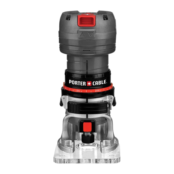
Summary of Contents for Porter-Cable PCE6430
- Page 1 LAMINATE TRIMMER Instruction manual PCE6430 PCE6435...
- Page 2 TABLE OF CONTENTS SAFETY GUIDELINES- DEFINITIONS ..............2 GENERAL POWER TOOL SAFETY WARNINGS ............ 2 ADDITIONAL SPECIFIC SAFETY RULES ..............4 COMPONENTS ...................... 7 OPERATION ......................6 MAINTENANCE ....................12 SERVICE ......................13 ACCESSORIES ....................13 SAFETY GUIDELINES - DEFINITIONS DANGER indicates an imminently hazardous situation which, if not avoided, will result in death or serious injury.
- Page 3 b) Avoid body contact with earthed or grounded surfaces such as pipes, radiators, ranges and refrigerators. There is an increased risk of electric shock if your body is earthed or grounded. c) Do not expose power tools to rain or wet conditions. Water entering a power tool will increase the risk of electric shock.
- Page 4 e) Maintain power tools. Check for misalignment or binding of moving parts, breakage of parts and any other condition that may affect the power tool’s operation. If damaged, have the power tool repaired before use. Many accidents are caused by poorly maintained power tools. f) Keep cutting tools sharp and clean.
- Page 5 • Not recommended for use in a router table. • Avoid climb-cutting (cutting in direction opposite than shown in Figure 7). Climb-cutting increases the chance for loss of control resulting in possible injury. When climb-cutting is required (backing around a corner), exercise extreme caution to maintain control of trimmer.
- Page 6 SAVE THESE INSTRUCTIONS MOTOR Be sure your power supply agrees with the nameplate marking. Voltage decrease of more than 10% will cause loss of power and overheating. PORTER-CABLE tools are factory tested; if this tool does not operate, check power supply. NOTICE: Do not operate your tool on a current on which the voltage is not within correct limits.
- Page 7 COMPONENTS (FIG. 1, 2) WARNING Never modify the power tool or any part of it. Damage or personal injury could result. Quick release tabs Sub-base screws Depth adjustment ring Guide pins C. On/off switch M. Locking lever adjustment screw D. Spindle lock button N.
- Page 8 FIG. 2 INTENDED USE This laminate trimmer is designed for professional flush and bevel trimming of laminated plastics and other similar materials that have a bonding agent too hard to be trimmed with ordinary tools. DO NOT use under wet conditions or in presence of flammable liquids or gases. This laminate trimmer is a professional power tool.
- Page 9 If the depth adjustment ring (B) is not on the motor, FIG. 3 thread the depth adjustment ring (B) onto the motor until the ring is positioned as shown. Insert the motor into the base by aligning the groove in the back of the motor with the guide pins (L) on the base.
- Page 10 COLLETS (FIG. 1) NOTE: Never tighten the collet nut (O) without first installing a bit in it. Tightening an empty collet nut, even by hand, can damage the collet (N). LOCKING LEVER ADJUSTMENT (FIG. 2) Excessive force should not be used to clamp the locking lever (H). Using excessive force may damage the base.
- Page 11 ADJUSTING THE DEPTH OF CUT (FIG. 6) Select and install the desired bit. Refer to Bit Installation and Removal. FIG. 6 Assemble base to motor, ensuring base is attached to the depth adjustment ring. Place laminate trimmer on the work piece. Open the locking lever (H) and turn the depth adjustment ring (B) until the bit just touches the work piece.
- Page 12 SHAPING THE OUTSIDE EDGE OF A PIECE OF STOCK Shape the end grain, left to right Shape the straight grain side moving left to right Cut the other end grain side Finish the remaining straight grain edge NOTE: Make several light passes instead of one heavy pass for better quality work. VARIABLE SPEED CONTROL (FIG.
- Page 13 CLEANING WARNING Periodically blowing dust and chips out of the motor housing using clean, dry compressed air is a suggested maintenance procedure. To reduce the risk of serious personal injury, ALWAYS wear ANSI Z87.1 safety glasses while using compressed air. WARNING When cleaning, use only mild soap and a damp cloth on plastic parts.


Need help?
Do you have a question about the PCE6430 and is the answer not in the manual?
Questions and answers