
Related Manuals for Schmalz ECBPi CobotPump


Summary of Contents for Schmalz ECBPi CobotPump
- Page 1 ECBPi CobotPump Operating Instructions WWW.SCHMALZ.COM EN-US · 30.30.01.01866 · 00 · 11/18...
- Page 2 Published by © J. Schmalz GmbH, 11/18 This document is protected by copyright. J. Schmalz GmbH retains the rights established thereby. Repro- duction of the contents, in full or in part, is only permitted within the limits of the legal provisions of copyright law. Any modifications to or abridgments of the document are prohibited without explicit writ- ten agreement from J. Schmalz GmbH.
-
Page 3: Table Of Contents
Contents Contents 1 Important information ........................... 5 1.1 Note on using these operating instructions .................. 5 1.2 The technical documentation is part of the product ................ 5 1.3 Warnings in this document........................ 5 1.4 Symbol.............................. 5 2 Fundamental Safety Instructions........................ 6 2.1 Standards of Technology ........................ 6 2.2 Intended Use............................ - Page 4 Contents 5.4 Production Setup Profiles ........................ 14 6 Transport and storage .......................... 15 6.1 Checking the Delivery .......................... 15 7 Installation.............................. 16 7.1 Installation Instructions........................ 16 7.2 Mechanical Attachment........................ 16 7.3 Electrical Connection.......................... 17 7.3.1 Description of the Electrical Connection.................. 17 7.3.2 Description of the Connection Cable .................. 18 7.3.3 Mounting the Connection Cable ....................
-
Page 5: Important Information
3. Pass on the technical documentation to subsequent users. ð Schmalz is not liable for damage or malfunctions that result from failure to heed these instructions. If you still have questions after reading the technical documentation, contact the Customer Service Center www.schmalz.com/services... -
Page 6: Fundamental Safety Instructions
Fundamental Safety Instructions 2 Fundamental Safety Instructions 2.1 Standards of Technology The CobotPump is state of the art and operationally reliable as delivered. The operating instructions con- tain important information on using the system. NOTE Damage to plants and systems 4 Read the instructions closely and keep them for later use. 2.2 Intended Use The CobotPump is designed to generate a vacuum for gripping and transporting objects when used in conjunction with suction cups. -
Page 7: Changes To The Vacuum Generator
Fundamental Safety Instructions 2.4 Changes to the Vacuum Generator Schmalz assumes no liability for consequences of modifications over which it has no control: 1. The vacuum generator must be operated only in its original condition as delivered. 2. Use only original spare parts from Schmalz. -
Page 8: Product Description
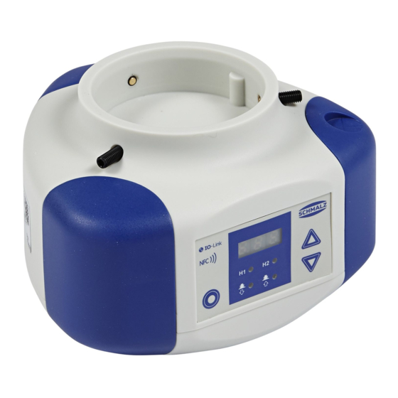
Product description 3 Product description 3.1 Design of the CobotPump Housing Shock protection "bumper" Cable duct prepared Set screw (3x) for mounting the flange Electrical connection, 5-pin M12 connec- plate [7], max. tightening torque 0.6 Nm tor (ECBPi 48V DC M12-5) Vacuum opening Flange module (mechanical interface for vacuum gripper) Flange plate (mechanical interface for col- laborative robots) -
Page 9: Depositing The Workpiece
Product description If the volume to be evacuated is small, then the set limit value H1 may be exceeded before the vacuum is switched off. This system behavior does not constitute an error. If leakage causes the system vacuum to drop about 10 percent below the limit value H1, then the pump is switched on again. -
Page 10: Technical Data
Technical Data 4 Technical Data 4.1 Electrical Parameters Parameter Sym- Limit values Unit Note min. typ. max. Supply voltage 38.9 PELV Rated current from U — = 48.0 V CAN bus data transfer rate — — — kbit/s — 1) The power supply must correspond to the regulations in accordance with EN60204 (protected extra-low voltage). -
Page 11: Maximum Torque
Technical Data horizontal installation vertical installation L = 100 mm Fmax. = 25 N Fmax. = 100 N 4.2.3 Maximum Torque Connection Max. torque Thread G1 1.3 Nm Attachment (3 set screws M5x16) 0.6 Nm 4.2.4 Dimensions Dmk1 151.5 88.6 M4-IG EN-US · 30.30.01.01866 · 00 · 11/18 11 / 30... - Page 12 Technical Data All dimensions given in millimeters [mm]. 12 / 30 EN-US · 30.30.01.01866 · 00 · 11/18...
-
Page 13: Description Of Functions
Description of Functions 5 Description of Functions 5.1 Automatic Operation Once the CobotPump is connected to the power supply, it is ready for operation and enters automatic op- eration mode. This is the normal operating mode, in which the CobotPump is operated by the system con- troller. -
Page 14: Production Setup Profiles
Description of Functions Vacuum H1 – 10% H2-h2 Time Speed of pump 100% Time 5.4 Production Setup Profiles The CobotPump can store up to four different production setup profiles (P-0 to P-3). All important param- eter data for workpiece handling is stored in these profiles. The profile is selected by means of the process data byte PDO byte 0. -
Page 15: Transport And Storage
1. Compare the entire delivery with the supplied delivery notes to make sure nothing is missing. 2. Damage caused by defective packaging or in transit must be reported immediately to the carrier and J. Schmalz. EN-US · 30.30.01.01866 · 00 · 11/18... -
Page 16: Installation
Installation 7 Installation 7.1 Installation Instructions CAUTION Improper installation or maintenance Personal injury or damage to property 4 Prior to installation and before maintenance work, the vacuum generator must be dis- connected from the power supply and secured against unauthorized restart! For safe installation, the following instructions must be observed: 1. -
Page 17: Electrical Connection
Installation 7.3 Electrical Connection 7.3.1 Description of the Electrical Connection NOTE In addition to the rated current, current peaks of up to 0.8 A flow for a short time in the default setting. Damage to the robot due to current pulses! 4 Refer to the technical description of the robot for the maximum current. CAUTION Change of output signals when product is switched on or plug is connected Personal injury or damage to property! -
Page 18: Description Of The Connection Cable
Installation Mounting and removal may be performed only when the device is unpressurized and disconnected from the mains. Electrical connections must be firmly connected and secured to the CobotPump. When connecting to the power supply, take note of the following: •... -
Page 19: Mounting The Connection Cable
Installation 7.3.3 Mounting the Connection Cable CAUTION Risk of getting caught by the connection cable when the collaborative robot moves. Injury due to limbs or hair getting caught. 4 Route the connection cable as close to the robot arm as possible. 4 Avoid the danger zone. -
Page 20: Start Of Operations
Installation 7.4 Start of Operations Flange module Vacuum The vacuum is routed to the vacuum gripping system via the flange module, pos. (6). 20 / 30 EN-US · 30.30.01.01866 · 00 · 11/18... -
Page 21: Operation
Operation 8 Operation 8.1 Preparations WARNING Extraction of hazardous media, liquids or bulk material Personal injury or damage to property! 4 Do not extract harmful media such as dust, oil mists, vapors, aerosols etc. 4 Do not extract aggressive gases or media such as acids, acid fumes, bases, biocides, dis- infectants or detergents. -
Page 22: Maintenance
4 If the performance drops noticeably, clean the sieve with a paintbrush. If it is heavily soiled, you can send the CobotPump to Schmalz for repairs and replacement of the sieve (subject to a fee). -
Page 23: Warranty
Wearing parts are not covered by the warranty. NOTE Use of non-original spare parts Malfunctions or damage to the equipment 4 Use only original and spare parts from J. Schmalz. Otherwise the warranty is void. EN-US · 30.30.01.01866 · 00 · 11/18 23 / 30... -
Page 24: Spare And Wearing Parts, Accessories
Spare and Wearing Parts, Accessories 11 Spare and Wearing Parts, Accessories 11.1 Spare and Wearing Parts Maintenance work may only be carried out by qualified personnel. WARNING Risk of injury due to incorrect maintenance or troubleshooting 4 Check the proper functioning of the product, especially the safety features, after every maintenance or troubleshooting operation. -
Page 25: Troubleshooting
4 Clean sieve or have it re- Vacuum level is not reached or Press-in screen is contaminated vacuum is built up too slowly placed by Schmalz if neces- sary Leakage at vacuum gripper 4 Check vacuum gripper and replace if necessary... -
Page 26: Decommissioning And Recycling
Decommissioning and recycling 13 Decommissioning and recycling 13.1 Disposing of the Device 1. Dispose of the product properly after replacement or decommissioning. 2. Observe the country-specific guidelines and legal obligations for waste prevention and disposal. Component Material Housing PUR vacuum cast resin Bumper 1 and 2 Elastomer Inner components... -
Page 27: Appendix
Appendix 14 Appendix See also 2 ECBPi_CE_30.30.01.01452-02_DE-EN-FR-ES-IT-NL.pdf [} 28] 14.1 Factory Settings Function Factory settings for the production setup profile P-0 Limit value H1 550 mbar Limit value H2 400 mbar Hysteresis h2 20 mbar EN-US · 30.30.01.01866 · 00 · 11/18 27 / 30...
Need help?
Do you have a question about the ECBPi CobotPump and is the answer not in the manual?
Questions and answers