
Related Manuals for Schmalz SCPLb


Summary of Contents for Schmalz SCPLb
- Page 1 Operating instructions Basic Ejector SCPLb WWW.SCHMALZ.COM EN-US · 30.30.01.03849 · 03 · 02/25 Translation of the original operating instructions...
- Page 2 Published by © J. Schmalz GmbH, 02/25 This document is protected by copyright. J. Schmalz GmbH retains the rights established thereby. Repro- duction of the contents, in full or in part, is only permitted within the limits of the legal provisions of copyright law. Any modifications to or abridgments of the document are prohibited without explicit writ- ten agreement from J. Schmalz GmbH.
-
Page 3: Table Of Contents
Contents Contents 1 Important Information.......................... 5 Note on Using this Document...................... 5 The technical documentation is part of the product ................ 5 Type Plate............................. 5 Symbols.............................. 6 2 Fundamental Safety Instructions ...................... 7 Intended Use ............................ 7 Non-Intended Use.......................... 7 Personnel Qualifications........................ - Page 4 Contents 13.3 Cleaning or Replacing the Ejector Module .................. 27 13.4 Replacing the Silencer ........................ 30 13.5 Cleaning or Replacing the Screen in the Vacuum Connection ............ 31 14 Spare and Wearing Parts ........................... 32 14.1 Replacing the Valve ........................... 32 15 Accessories..............................
-
Page 5: Important Information
ð Failure to follow the instructions in these Operating instructions may result in injuries! ð Schmalz is not liable for damage or malfunctions that result from failure to heed these instructions. If you still have questions after reading the technical documentation, contact Schmalz Service at: www.schmalz.com/services... -
Page 6: Symbols
1 Important Information 1.4 Symbols This symbol indicates useful and important information. ü This symbol represents a prerequisite that must be met before an action is performed. 4 This symbol represents an action to be performed. ð This symbol represents the result of an action. Actions that consist of more than one step are numbered: 1. -
Page 7: Fundamental Safety Instructions
2.2 Non-Intended Use Schmalz does not accept any liability for any direct or indirect losses or damages that result from using the product. This applies, in particular, to any use of the product that is not in accordance with the in- tended purpose and to any use that is not described or mentioned in this documentation. -
Page 8: Warnings In This Document
2 Fundamental Safety Instructions Applicable for Germany: A qualified employee is defined as an employee who has received technical training and has the knowl- edge and experience – including knowledge of applicable regulations – necessary to enable him or her to recognize possible dangers and implement the appropriate safety measures while performing tasks. -
Page 9: Modifications To The Product
4 Do not look into vacuum openings such as suction cups, suction lines and hoses. 2.6 Modifications to the Product Schmalz assumes no liability for consequences of modifications over which it has no control: 1. The product must be operated only in its original condition as delivered. -
Page 10: Product Name
3 Product Name 3 Product Name The breakdown of the item designation (e.g. SCPLc-100-HV-NC-ABC00001C) is as follows: Property Variants Type SCPL Version Basic: b Controlled: c Size 25, 50, 75.100, 125 and 150 Shape HV, high vacuum HF, high flow Suction valve control NO (normally open), sucks when no voltage is applied NC (normally closed), does not suck when no voltage is ap- plied... -
Page 11: Product Design
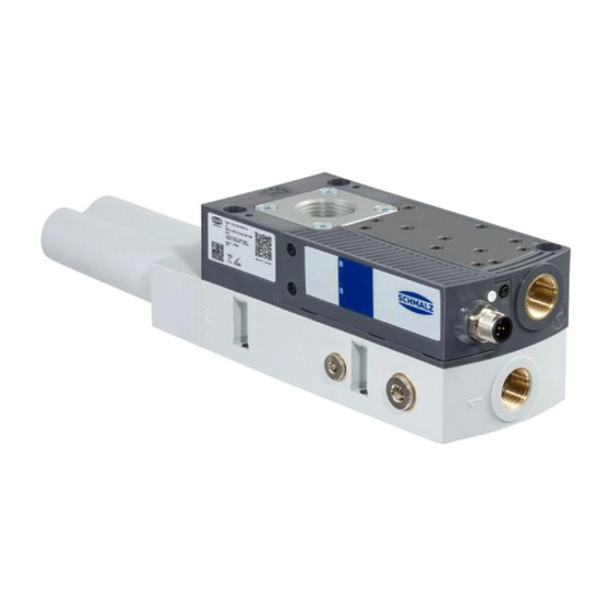
4 Product Design 4 Product Design Silencer Electrical connection Vacuum connection Display element Compressed air connection Mounting holes, 4x EN-US · 30.30.01.03849 · 03 · 02/25 11 / 40... -
Page 12: Indicator Elements In Detail
5 Indicator Elements in Detail 5 Indicator Elements in Detail The device has two light-emitting diodes (LEDs) for visual status display. Suction LED (S) Blow off LED (B) Position Display Status NC variant NO variant Lit yellow Suction from ejector No suction from ejector Lit yellow Ejector blows off Ejector not blowing off... -
Page 13: Technical Data
6 Technical Data 6 Technical Data 6.1 General parameters Parameter High vacuum HV variant High flow HF variant Max. vacuum 900 mbar 600 mbar Working temperature 0° C to 55° C Optimum flow pressure 4.5 bar for SCPL 25 - 100 5.5 bar for SCPL 125 - 150 Operating pressure 3 bar to 6 bar Degree of protection... -
Page 14: Dimensions
6 Technical Data At 4.5 bar 6.4 Dimensions 153.5 54.5 13.5 113.5 73.5 124.5 13.8 Type SCPL 25/50 HF/HV 3/8" female 3/4" fe- thread male thread M4-IG M12x1 male SCPL 25/50 HF/HV NPT NPT3/8" fe- NPT3/4" thread male thread female thread SCPL 75/100 HF/HV 97.8 3/8"... -
Page 15: Pneumatic Circuit Plans
6 Technical Data 6.5 Pneumatic Circuit Plans Key: Normally closed Normally open Compressed air connection Vacuum connection Exhaust outlet NO version EN-US · 30.30.01.03849 · 03 · 02/25 15 / 40... - Page 16 6 Technical Data NC version 16 / 40 EN-US · 30.30.01.03849 · 03 · 02/25...
-
Page 17: Description Of Functions
7 Description of Functions 7 Description of Functions 7.1 Applying Suction to the Workpiece/Part (Vacuum Generation) The ejector is designed for handling and holding workpieces by means of a vacuum in combination with suction systems. The vacuum is generated in a nozzle according to the venturi principle, using suction generated by the flow of accelerated compressed air. -
Page 18: Checking The Delivery
1. Compare the entire delivery with the supplied delivery notes to make sure nothing is missing. 2. Damage caused by defective packaging or occurring in transit must be reported immediately to the carrier and J. Schmalz GmbH. 18 / 40 EN-US · 30.30.01.03849 · 03 · 02/25... -
Page 19: Installation
9 Installation 9 Installation 9.1 Installation Instructions CAUTION Compressed air or vacuum in direct contact with the eye Severe eye injury! 4 Wear eye protection. 4 Do not look into compressed air openings. 4 Do not look into vacuum openings, e.g. suction cups. CAUTION Noise pollution due to incorrect installation of the pressure and vacuum con- nections... -
Page 20: Mounting
9 Installation 9.2 Mounting The illustrations shown below may deviate from the customer’s version because they serve as examples of different versions of the product. The product can be mounted in any position. 4 When installing the ejector, make sure that the area around the exhaust air opening (1) remains unobstructed to ensure the unim- peded discharge of the escaping air. -
Page 21: Pneumatic Connection
9 Installation Alternative attachment with mounting bracket For attachment, the product is designed with threaded inserts. 4 Use mounting brackets (see Accessories sec- tion). 9.3 Pneumatic Connection 9.3.1 Instructions for the Pneumatic Connection 1. Ensure that you make all connections correctly and never close them off – danger of bursting! 2. -
Page 22: Electrical Connection
9 Installation 9.3.2 Connecting the Compressed Air and Vacuum Compressed air connector (marking 1) Vacuum connection (marking 2) ü The connectors required for the hose connections are fitted by the customer. 1. Connect the compressed air hose. Maximum tightening torque = 10 Nm 2. - Page 23 Direct connection to the control unit of the higher-level machine To directly connect the ejector to the control unit, a Schmalz connection cable can be used, for example: • Ejector with 5-pin M12 connector: M12-5 connection cable with open end, 5 m, part no.
-
Page 24: Start Of Operations
10 Start of Operations 10 Start of Operations 10.1 General Preparations WARNING Extraction of hazardous media, liquids or bulk material Personal injury or damage to property! 4 Do not extract harmful media such as dust, oil mists, vapors, aerosols etc. 4 Do not extract aggressive gases or media such as acids, acid fumes, bases, biocides, dis- infectants or detergents. -
Page 25: Troubleshooting
No actuator supply voltage spond signment No compressed air supply 4 Check the compressed air supply. 4 Check the ejector and contact Schmalz Ejector is faulty. Service if necessary. 4 Clean or replace the screen Vacuum level is not Dirty screen... -
Page 26: Warranty
12 Warranty 12 Warranty This system is guaranteed in accordance with our general terms of trade and delivery. The same applies to spare parts, provided that these are original parts supplied by us. We are not liable for any damage resulting from the use of non-original spare parts or accessories. The exclusive use of original spare parts is a prerequisite for the proper functioning of the ejector and for the validity of the warranty. -
Page 27: Maintenance And Cleaning
13 Maintenance and Cleaning 13 Maintenance and Cleaning 13.1 Safety Instructions Maintenance work may only be carried out by qualified personnel. 4 Create atmospheric pressure in the ejector’s compressed air circuit before working on the system! WARNING Failure to follow the instructions in these Operating instructions may result in injuries! 4 Read the Operating instructions carefully and observe the contents. - Page 28 13 Maintenance and Cleaning 2. Pull the ejector module (4) out of the bore- hole. Opening and cleaning the ejector module 1. Turn the nozzle fitting (1.2) relative to the main body (1.1) to the “unlocked” position. 2. Pull the nozzle fitting (1.2) out of the main body (1.1), pulling only in the axial direction.
- Page 29 13 Maintenance and Cleaning 5. Grease the O-rings slightly before mounting the ejector module. Assembling a new or cleaned ejector module 1. Lightly grease the ejector module O-rings (4) before mounting. 2. Ensure that the ejector module (4) is in the correct position and push it into the opening until it stops, with the suction openings of the ejector module (4) as shown.
-
Page 30: Replacing The Silencer
13 Maintenance and Cleaning 13.4 Replacing the Silencer Heavy infiltration of dust, oil, etc. may contaminate the silencer and reduce the suction capacity. Cleaning the silencer is not recommended due to the capillary effect of the porous material. If the suction capacity decreases, replace the silencer: ü... -
Page 31: Cleaning Or Replacing The Screen In The Vacuum Connection
13 Maintenance and Cleaning 13.5 Cleaning or Replacing the Screen in the Vacuum Connection The vacuum connection contains a screen in which dust, chippings and other solid materials may accumu- late over time. If there is a noticeable reduction in performance, simply clean or replace the screen. ü... -
Page 32: Spare And Wearing Parts
ERS SEP-22 6xRUE-KLAP 10.02.01.01450 flap Spare part for ejector ERS VENT SCPLb/c/i 10.02.02.07698 14.1 Replacing the Valve A faulty valve can be replaced as described below. ü The spare part set with part no. 10.02.02.07698 (two valves and one sealing) is provided by the cus- tomer. - Page 33 14 Spare and Wearing Parts 3. Screw a screw with an M5 thread into the cen- tral thread of the valve (3) to be replaced (at least 5 threads). 4. Pull the valve (3) out of the hole by pulling on the screw.
-
Page 34: Accessories
— Dust filter STF G1-1/4-IG N 10.07.01.00008 From SCPL100 — Extension (round) VRL-R G1 50.3x39 10.02.01.02093 For SCPLb size 100 to 150 Extension (round) VRL-R NPT3/4 10.02.01.02094 For SCPLb size 25 to 75 44.5x39 AL Extension (round) VRL-R G3/4 10.02.01.02096 For SCPLb size 25 to 75 44.5x39 AL... - Page 35 15 Accessories Designation Type Part no. Note Hose clamp The through hole in the extension (1) is used to measure the vacuum, for example by mounting a vacuum switch VSi or a pressure gauge. Sealing the threads is the responsibility of the operating company.
-
Page 36: Converting The Vacuum Connection To A Hose Sleeve
15 Accessories 15.1 Converting the Vacuum Connection to a Hose Sleeve The vacuum connection can be converted to a connection using a hose sleeve. For the corresponding sizes, the part numbers of the appropriate hose sleeves are listed in the accessories. The illustrations shown below may deviate from the customer’s version because they serve as examples of different versions of the product. -
Page 37: Decommissioning And Disposal
16 Decommissioning and Disposal 16 Decommissioning and Disposal 16.1 Disposing of the Product The components may only be prepared for disposal by qualified specialists. 1. Dispose of the product properly after replacement or decommissioning. 2. Observe the country-specific guidelines and legal obligations for waste prevention and disposal. 16.2 Materials Used The table below shows the materials used: Component... -
Page 38: Declarations Of Conformity
17 Declarations of Conformity 17 Declarations of Conformity 17.1 EU Declaration of Conformity The manufacturer Schmalz confirms that the product described in these operating instructions fulfills the following applicable EU directives: 2006/42/EC Machinery Directive 2014/30/EU Electromagnetic Compatibility 2011/65/EU Directive on the restriction of the use of certain hazardous substances in... - Page 39 EN-US · 30.30.01.03849 · 03 · 02/25 39 / 40...
-
Page 40: Handling Systems
At Your Service Worldwide Vacuum automation Handling systems WWW.SCHMALZ.COM/AUTOMATION WWW.SCHMALZ.COM/EN-US/VACUUM-LIFTERS- AND-CRANE-SYSTEMS J. Schmalz GmbH Johannes-Schmalz-Str. 1 72293 Glatten, Germany T: +49 (0) 7443 2403-0 schmalz@schmalz.de WWW.SCHMALZ.COM...
Need help?
Do you have a question about the SCPLb and is the answer not in the manual?
Questions and answers