
Related Manuals for Perkins 402F-05


Summary of Contents for Perkins 402F-05
- Page 1 SEBU9064-08 (en-us) May 2023 Operation and Maintenance Manual 402F-05, 403F-07, 403F-11 and 403F-15 Industrial Engines...
- Page 2 If a tool, procedure, work method or operating technique that is not specifically recommended by Perkins is used, you must satisfy yourself that it is safe for you and for others. You should also ensure that you are authorized to perform this work, and that the product will not be damaged or become unsafe by the operation, lubrication, maintenance or repair procedures that you intend to use.
-
Page 3: Table Of Contents
SEBU9064-08 Table of Contents Table of Contents Maintenance Interval Schedule....... 68 Warranty Section Foreword ............4 Warranty Information........104 Safety Section Reference Information Section Safety Messages..........6 Reference Materials ........105 General Hazard Information......7 Index Section Burn Prevention..........10 Index.............. -
Page 4: Foreword
State of arises regarding your engine, or this manual, please California to cause cancer, birth defects, consult with your Perkins dealer or your Perkins distributor for the latest available information. and other reproductive harm. WARNING – This product can... - Page 5 Perkins distributor offers various options regarding overhaul programs. If you experience a major engine failure, there are also numerous after failure overhaul options available. Consult with your Perkins dealer or your Perkins distributor for information regarding these options.
-
Page 6: Safety Section
Replace any warning sign that is damaged or missing. If a warning sign is attached to a part of the engine that is replaced, install a new warning sign on the replacement part. Your Perkins dealer or your distributor can provide new warning signs. (A) Universal Warning... -
Page 7: General Hazard Information
General Hazard Information Illustration 2 g03378379 Typical examples (A) Location of warning label (2) 403F-07 (4) 403F-15 (1) 402F-05 (3) 403F-11 i08312758 General Hazard Information Illustration 4 g00702020 Wear a hard hat, protective glasses, and other protective equipment, as required. - Page 8 SEBU9064-08 Safety Section General Hazard Information Keep the engine free from foreign material. Remove The direct application of pressurized air or debris, oil, tools, and other items from the deck, from pressurized water to the body could result in personal walkways, and from steps.
- Page 9 Hexavalent Chromium Perkins equipment and replacement parts comply with applicable regulations and requirements where originally sold. Perkins recommends the use of only genuine Perkins replacement parts. Hexavalent chromium has occasionally been detected on exhaust and heat shield systems on Perkins engines.
-
Page 10: Burn Prevention
• Wear an approved respirator if there is no other good hygiene, and adhering to safe work practices way to control the dust. when handling the equipment or parts. Perkins also recommends the following: • Comply with applicable rules and regulations for the work place. -
Page 11: Fire Prevention And Explosion Prevention
SEBU9064-08 Safety Section Fire Prevention and Explosion Prevention Coolant Cooling system conditioner contains alkali. Alkali can cause personal injury. Do not allow alkali to contact When the engine is at operating temperature, the the skin, the eyes, or the mouth. engine coolant is hot. - Page 12 Personal injury, property damage, or engine damage could result. If the application involves the presence of combustible gases, consult your Perkins dealer and/ or your Perkins distributor for additional information about suitable protection devices. Remove all flammable combustible materials or conductive materials such as fuel, oil, and debris from the engine.
-
Page 13: Crushing Prevention And Cutting Prevention
Do not clip any other items to the high- pressure lines. Repair any lines that are loose or damaged. Leaks can cause fires. Consult your Perkins dealer or your NOTICE For initial start-up of a new or rebuilt engine, and for Perkins distributor for repair or for replacement parts. -
Page 14: Engine Starting
SEBU9064-08 Safety Section Engine Starting Before starting the engine, ensure that no one is on, Engine exhaust contains products of combustion underneath, or close to the engine. Ensure that the which can be harmful to your health. Always start the area is free of personnel. - Page 15 SEBU9064-08 Safety Section Electrical System Check the electrical wires daily for wires that are loose or frayed. Tighten all loose electrical wires before the engine is started. Repair all frayed electrical wires before the engine is started. See the Operation and Maintenance Manual for specific starting instructions.
-
Page 16: Product Information Section
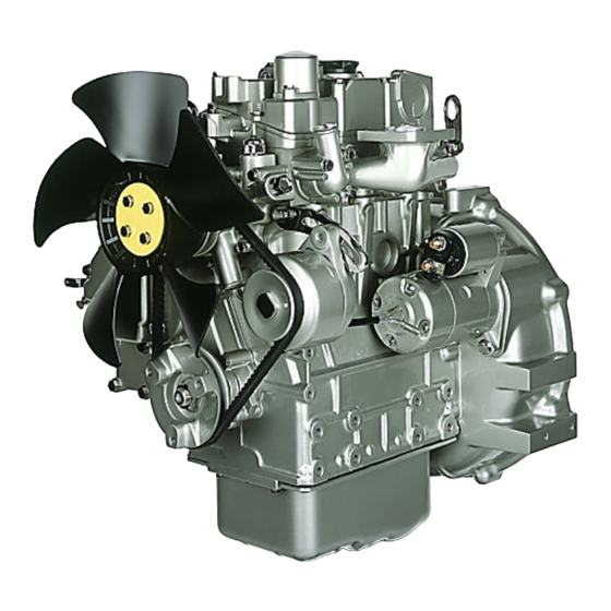
SEBU9064-08 Product Information Section General Information Product Information Section General Information i08136270 Model View Illustrations 403F-15 Engine View Illustration 11 g03378808 Typical example (1) Rear lifting eye (5) Low mounted oil filler cap (9) Oil filter (2) Top oil filler cap (6) Fuel injection pump (10) Electronically controlled actuator or (3) Front lifting eye... - Page 17 SEBU9064-08 Product Information Section Model View Illustrations Illustration 12 g03379877 (12) Air intake (15) Solenoid for starter (18) Fan belt (13) Coolant outlet (16) Starting motor (19) Coolant intake connection (14) Exhaust manifold (17) Alternator...
- Page 18 SEBU9064-08 Product Information Section Model View Illustrations 403F-11 Engine View Illustration 13 g06563478 Typical example (1) Oil filler cap (5) Oil level gauge (dipstick) (9) Secondary fuel filter (2) Front engine lifting eye (6) Oil filter (10) Valve mechanism cover breather (3) Coolant drain tap (7) Stop solenoid (11) Air cleaner assembly...
- Page 19 SEBU9064-08 Product Information Section Model View Illustrations Illustration 14 g06563484 Typical example (12) Exhaust manifold with combined (14) Starting motor (17) Coolant temperature sensor silencer (15) Alternator (18) Coolant temperature regulator housing (13) Rear engine lifting eye (16) Fan belt (19) Oil pressure switch...
- Page 20 SEBU9064-08 Product Information Section Model View Illustrations 403F-07 Engine View With Factory Radiator Illustration 15 g06537769 Typical example (1) Air cleaner assembly (3) Flywheel with cooling fins (5) Radiator assembly (2) Rear engine lifting eye (4) Exhaust manifold and muffler assembly (6) Radiator cap...
- Page 21 SEBU9064-08 Product Information Section Model View Illustrations Illustration 16 g06537770 Typical example (7) Front engine lifting eye (9) Secondary fuel filter (8) Radiator coolant drain valve (10) Air cleaner assembly valve...
- Page 22 SEBU9064-08 Product Information Section Model View Illustrations 402F-05 Engine View Illustration 17 g06538327 Typical example (1) Front engine lifting eye (4) Flywheel (7) Rear engine lifting eye (2) Dipstick (5) Secondary fuel filter (3) Oil filter (6) Fuel valve...
- Page 23 SEBU9064-08 Product Information Section Model View Illustrations Illustration 18 g06538342 Typical example (8) Oil filler cap (10) Oil drain plug (12) Engine crankcase breather (9) Starting motor (11) Alternator Fuel System Components Illustration 19 g03379882 Typical examples (1) In-line fuel filter (2) Electric fuel pump...
- Page 24 SEBU9064-08 Product Information Section Model View Illustrations (3) Primary fuel filter (4) Secondary fuel filter (element type) (5) Secondary fuel filter Note: The electric fuel pump is an option, engines may have a mechanical fuel lift pump installed.
- Page 25 SEBU9064-08 Product Information Section Model View Illustrations Illustration 20 g06119854 (6) Fuel filter for a 1000-hour service (7) Mechanical fuel lift pump Components for Electronic Control Illustration 21 g03379884 (1) Electronic Control Module (ECM) (3) Atmospheric Pressure Sensor (4) Actuator (2) Speed sensor (Barometric Pressure Sensor)
- Page 26 Bore 67 mm (2.64 inch) Stroke 72 mm (2.83 inch) There are four Perkins engines in the 400F series Displacement 0.507 L (30.939 in that are below 19Kw power band. These engines are, 402F-05, 403F-07, 403F-11, and the 403F-15. These...
- Page 27 SEBU9064-08 Product Information Section Product Description 403F-15 Engine (Table 2, contd) Aspiration Naturally Aspirated Compression Ratio 23.5:1 Firing Order 1-2-3 Rotation that is viewed from the Counterclockwise flywheel Valve Lash Setting (Inlet) 0.20 mm (0.008 inch) Valve Lash Setting (Exhaust) 0.20 mm (0.008 inch) Injection Indirect...
-
Page 28: Product Identification Information
Plate Locations and Film Locations Perkins engines are identified by a serial number. This serial number is shown on a serial number plate. The plate is mounted above the fuel injection pump on the right-hand side of the engine block. - Page 29 SEBU9064-08 Product Information Section Reference Information i05335976 Reference Information Information for the following items may be needed to order parts. Locate the information for your engine. Record the information in the appropriate space. Make a copy of this list for a record. Keep the information for future reference.
-
Page 30: Operation Section
Alterations to the lifting eyes and/or the engine make the lifting eyes and the lifting fixtures obsolete. If alterations are made, ensure that correct lifting devices are provided. Consult your Perkins dealer or your Perkins distributor for information regarding fixtures for correct engine lifting. - Page 31 Operation Section Product Storage Sealed Coolant System i05335259 Product Storage Ensure that the cooling system is filled with Perkins ELC, or an antifreeze that meets “ASTM D6210” specification. Perkins are not responsible for damage which may Open Cooling System occur when an engine is in storage after a period in service.
-
Page 32: Features And Controls
Ammeter – This gauge indicates the Determine and correct the cause of any significant amount of charge or discharge in the change in the readings. Consult your Perkins dealer or your Perkins distributor for assistance. battery charging circuit. Operation of the indicator should be to the right side of “... - Page 33 Sensors and Electrical Components The following sensors or switches are installed on the 402F-05, 403F-07, 403F-11, and the 403F-15 engines: • Oil pressure switch • Coolant temperature sensor • Atmospheric pressure sensor (Barometric pressure sensor) •...
- Page 34 Note: Due to individual applications the atmosphere • Electric fuel pump pressure sensor (3) may appear different from the illustration. Electrical components install on the 402F-05, 403F- 07, 403F-11, and the 403F-15 engines: • Alternator • Starting motor • Glow plugs •...
- Page 35 SEBU9064-08 Operation Section Sensors and Electrical Components Illustration 31 g03381126 Typical examples (7) Alternator (9) Glow plugs (11) Fuel pump (8) Starting motor (10) Electronic control model (Controller) (12) Multi-function lamp When the keyswitch is in the OFF position, the multi- function lamp will not be illuminated.
-
Page 36: Engine Diagnostics
SEBU9064-08 Operation Section Engine Diagnostics Engine Diagnostics i05339798 Self-Diagnostics The electronic engines can perform a self- diagnostics test. When the system detects an active problem, a diagnostic lamp is activated. This lamp is a multi function lamp that is located on the electronic control module. - Page 37 Oil pressure switch malfunction. Engine will start, but the engine Check harness connection. If the Disconnection of Oil pressure will shut down after 180 seconds fault remains contact your Perkins switch. dealer or your Perkins distributor. Disconnection of Oil pressure harness.
- Page 38 Checking engine oil is part of the daily engine check. Operating an engine will a low level of engine oil can damage your engine. For more information on diagnostic messages and diagnostic tools contact your Perkins dealer or your Perkins distributor.
-
Page 39: Engine Starting
SEBU9064-08 Operation Section Engine Starting Engine Starting i09851847 Starting the Engine i04053911 Before Starting Engine Do not use aerosol types of starting aids such as Perform the required daily maintenance and other ether. Such use could result in an explosion and periodic maintenance before the engine is started. - Page 40 SEBU9064-08 Operation Section Starting with Jump Start Cables Note: The ambient weather condition will determine 2. Connect one positive end of the jump-start cable to the amount of time the glow plugs will require. If the the positive cable terminal of the discharged engine is warm, heat from the glow plugs will not be battery.
- Page 41 SEBU9064-08 Operation Section After Starting Engine Note: Gauge readings should be observed and the data should be recorded frequently while the engine is operating. Comparing the data over time will help to determine normal readings for each gauge. Comparing data over time will also help detect abnormal operating developments.
-
Page 42: Engine Operation
Fuel Conservation Practices The efficiency of the engine can affect the fuel economy. Perkins design and technology in manufacturing provides maximum fuel efficiency in all applications. Follow the recommended procedures in order to attain optimum performance for the life of the engine. -
Page 43: Cold Weather Operation
Cold Weather Operation • Check all rubber parts (hoses, fan drive belts,) weekly. Perkins Diesel Engines can operate effectively in • Check all electrical wiring and connections for any cold weather. During cold weather, the starting and fraying or damaged insulation. - Page 44 This condition will provide 240 V dc. The output can be 750/1000W. Consult longer service life for the engine bearings, the piston your Perkins dealer or your Perkins distributor for rings, and other parts. However, limit unnecessary more information.
- Page 45 −25° to -40°C (−13° to -72.°F). Note: Group 3 fuels reduce the life of the engine. The use of Group 3 fuels is not covered by the Perkins i05340086 warranty. Fuel and the Effect from Cold Group 3 fuels include Low Temperature Fuels and Aviation Kerosene Fuels.
- Page 46 Maintenance Manual in the Maintenance Section for more information on priming the fuel system. Fuel Heaters Fuel heaters help to prevent fuel filters from plugging in cold weather due to waxing. For further information on fuel heaters, consult your Perkins dealer or distributor.
-
Page 47: Engine Stopping
SEBU9064-08 Operation Section Engine Stopping Engine Stopping i03756631 After Stopping Engine i06832774 Stopping the Engine Note: Before you check the engine oil, do not operate the engine for at least 10 minutes in order to allow the engine oil to return to the oil pan. NOTICE •... -
Page 48: Maintenance Section
OEM specifications for the capacity of the auxiliary oil filter. The Total Lubrication System includes the capacity for the 402F-05 Engine Crankcase Oil Sump plus the capacity of factory installed oil fil- ters and other filters added to the lubrication system. Enter the... - Page 49 External System Per OEM required for the Total Cooling System. Total Cooling System 402F-05 Engine The External System includes a radiator or an expansion tank with the following components: heat exchanger and piping. Re- Table 13 fer to the OEM specifications.
- Page 50 Diesel Fuel Requirements Fluid Recommendations (General Fuel Information) Perkins is not in a position to continuously evaluate and monitor all worldwide distillate diesel fuel specifications that are published by governments and technological societies. • Glossary The "Perkins Specification for Distillate Diesel Fuel"...
- Page 51 SEBU9064-08 Maintenance Section General Fuel Information Table 17 "Perkins Specification for Distillate Diesel Fuel" Property UNITS Requirements “ASTM”Test “ISO/Other”Test Aromatics %Volume 35% maximum “D1319” “ISO 3837” %Weight 0.01% maximum “D482” “ISO 6245” Carbon Residue on 10% %Weight 0.35% maximum “D524”...
- Page 52 “BS 2869: 2010 CLASS A2 or EU equivalent” “EU Off-Road Diesel fuel. Acceptable from 2011 MUST have less than 10 PPM sulfur level” All the fuels must comply with the specification in the table for the Perkins Specification Distillate Diesel Fuel.
- Page 53 Viscosity Perkins 402F, 403F, and 403F series diesel engines have been designed to operate only with ULSD. By Viscosity is the property of a liquid of offering using the test methods “ASTM D5453, or ISO...
- Page 54 0.52 mm (0.0205 inch) will Protection Agency (EPA) and European Certification lead to reduced service life and premature failure of fuels. Perkins does not certify engines on any other the fuel system. fuel. The user of the engine has the responsibility of using the correct fuel that is recommended by the Fuel additives can enhance the lubricity of a fuel.
- Page 55 • Perkins recommend the use of oil analysis to Perkins strongly recommended that seasonally check the quality of the engine oil if biodiesel fuel operated engines have the fuel systems, including is used.
- Page 56 “Operation and Maintenance If biodiesel or biodiesel blends of fuel are to be used, Manual” Fluid Recommendations Perkins require the use of Perkins fuel cleaner. The use of the fuel is to remove deposits within the fuel Fuel for Cold-Weather Operation system that is created with the use of biodiesel.
- Page 57 Never add coolant to an overheated engine. Engine damage could result. Allow the engine to cool first. • Perkins recommends the use of bulk fuel filter / coalescer units which clean the fuel of both particulate contamination and water in a single...
- Page 58 SEBU9064-08 Maintenance Section Fluid Recommendations Table 19 NOTICE If the engine is to be stored in, or shipped to an area Acceptable Water with below freezing temperatures, the cooling system Property Maximum Limit must be either protected to the lowest outside tem- perature or drained completely to prevent damage.
- Page 59 However, ELC • SCA Supplement Coolant Additive contains organic corrosion inhibitors and antifoam agents with low amounts of nitrite. Perkins ELC has • ASTM American Society for Testing and been formulated with the correct amount of these...
- Page 60 Do not use standard supplemental coolant additive and allow to cool. (SCA). 5. Drain the cooling system. When using Perkins ELC, do not use standard SCA's or SCA filters. NOTICE Incorrect or incomplete flushing of the cooling system can result in damage to copper and other metal ELC Cooling System Cleaning components.
- Page 61 Dispose of the coolant according to local regulations. Flush the system with a 5 to 10 Table 24 percent solution of Perkins ELC. Fill the system Example Of The Equation For Adding The SCA To The Heavy- with the Perkins ELC.
- Page 62 “EMA Recommended Guideline on Diesel Engine Fluid Recommendations Oil”. In addition to Perkins definitions, there are other definitions that will be of assistance in purchasing lubricants. Recommended oil viscosities can be found in this publication, “Fluid Recommendations/ Engine Oil”...
- Page 63 The aftermarket additive could fail to mix highest ambient temperature that is anticipated. with the finished oil. This failure could produce sludge in the crankcase. Perkins discourages the use of Generally, use the highest oil viscosity that is aftermarket additives in finished oils.
- Page 64 SEBU9064-08 Maintenance Section Fluid Recommendations • The Oil Condition Analysis determines the loss of the oils lubricating properties. An infrared analysis is used to compare the properties of new oil to the properties of the used oil sample. This analysis allows technicians to determine the amount of deterioration of the oil during use.
-
Page 65: Maintenance Recommendations
Consult the OEM of the equip- • Electronically controlled valves ment or your Perkins dealer regarding welding on a chassis frame or rail. • Relays • Aftertreatment ID module... - Page 66 Refer to the standards for the engine or consult your (3) Keyswitch in the OFF position Perkins dealer or your Perkins distributor in order to (4) Battery disconnect switch in the open position determine if the engine is operating within the defined (5) Disconnected battery cables parameters.
- Page 67 SEBU9064-08 Maintenance Section Severe Service Application Maintenance can be difficult. The buildup can contain corrosive chemicals. Buildup – Compounds, elements, corrosive chemicals, and salt can damage some components. Altitude – Problems can arise when the engine is operated at altitudes that are higher than the intended settings for that application.
-
Page 68: Maintenance Interval Schedule
SEBU9064-08 Maintenance Section Maintenance Interval Schedule “ Engine Air Cleaner Element - Replace” ... i07787938 Maintenance Interval Schedule “ Fuel Filter (In-Line) - Replace” ....88 “... - Page 69 Maintenance Section Alternator - Inspect i02322311 Alternator - Inspect Perkins recommends a scheduled inspection of the alternator. Inspect the alternator for loose connections and correct battery charging. Check the ammeter (if equipped) during engine operation in order to ensure correct battery performance and/or correct performance of the electrical system.
- Page 70 SEBU9064-08 Maintenance Section Alternator and Fan Belts - Replace If twin belts are installed, check and adjust the 3. Tighten adjusting bolt (1) and tighten mounting tension on both belts. bolts and nut (2). Tighten bolt (3). Tighten all fixing to a torque of 25 N·m (221 lb in) Adjustment i05341723...
-
Page 71: Battery - Replace
SEBU9064-08 Maintenance Section Battery - Replace 5. Tighten bolt (1) and tighten bolt and nut (2). Tighten bolt (3). Tighten all bolts and nuts to a torque of 25 N·m (221 lb in). Refer to this Operation and Maintenance Manual, “Alternator and Fan Belts - Inspect/Adjust”... - Page 72 SEBU9064-08 Maintenance Section Battery Electrolyte Level - Check Note: Before the cables are connected, ensure that i08073707 the engine start switch is OFF. Coolant (Commercial Heavy- 7. Connect the cable from the starting motor to the Duty) - Change POSITIVE “+” battery terminal. 8.
- Page 73 Perkins to reclaim the coolant. For information regarding the disposal and the recycling of used coolant, consult your Perkins dealer or your Perkins distributor. Flush 1. Flush the cooling system with clean water to remove any debris.
- Page 74 SEBU9064-08 Maintenance Section Coolant (ELC) - Change 3. Fill the cooling system with Commercial Heavy- Clean the cooling system and flush the cooling system before the recommended maintenance Duty Coolant. Add Supplemental Coolant Additive interval if the following conditions exist: to the coolant.
- Page 75 Perkins to reclaim the coolant. For information regarding the disposal and the recycling of used coolant, consult your Perkins dealer or your Perkins distributor. Flush 1. Flush the cooling system with clean water to remove any debris.
- Page 76 Coolant Level - Check Engines With a Coolant Recovery Tank Note: The cooling system may not have been provided by Perkins. The procedure that follows is for typical cooling systems. Refer to the OEM information for the correct procedures. Illustration 47...
- Page 77 Loosen the cooling system Perkins engines incorporate a shunt design cooling pressure cap slowly in order to relieve the system and require operating the engine with a water pressure.
- Page 78 SEBU9064-08 Maintenance Section Cooling System Supplemental Coolant Additive (SCA) - Test/Add i03644948 NOTICE When any servicing or repair of the engine cooling Cooling System Supplemental system is performed the procedure must be per- Coolant Additive (SCA) - Test/ formed with the engine on level ground. This will al- low you to accurately check the coolant level.
-
Page 79: Engine - Clean
Note: The air filter system may not have been provided by Perkins. The procedure that follows, is i07091080 for a typical air filter system. Refer to the OEM information for the correct procedure. - Page 80 SEBU9064-08 Maintenance Section Engine Air Cleaner Service Indicator - Inspect • The air cleaner element should be replaced at 2. Inspect the top cover (1) and if necessary remove least one time per year. top cover to clean cover. Ensure that dirt cannot enter the air cleaner system with top cover Replace the dirty air cleaner elements with clean air removed.
-
Page 81: Engine Air Precleaner - Check/Clean
SEBU9064-08 Maintenance Section Engine Air Precleaner - Check/Clean The service indicator may need to be replaced frequently in environments that are severely dusty. i07819526 Engine Air Precleaner - Check/ Clean Illustration 50 g00103777 Typical service indicator Observe the service indicator. The air cleaner element should be cleaned or the air cleaner element should be replaced when one of the following conditions occur:... - Page 82 SEBU9064-08 Maintenance Section Engine Crankcase Breather - Replace Naturally Aspirated Engine 6. Install the breather cover (2) and the four screws (1). Tighten the screws. Crankcase Breather Turbocharged Engine Crankcase Breather Note: Turbocharged engines have different design breather systems. Illustration 52 g03380583 Typical example (1) Screws for the breather cover...
-
Page 83: Engine Oil Level - Check
“FULL” mark could cause your crankshaft to dip into the oil. The air bubbles created from the crankshaft When the engine mounts are supplied by Perkins the dipping into the oil reduces the oil's lubricating char- maintenance procedure will be supplied in the acteristics and could result in the loss of power or en- Disassembly and Assembly manual for your engine. -
Page 84: Drain
250 hours. If the engine is operated in severe service conditions, Perkins recommends the use of engine oil sampling. Refer to this Operation and Maintenance Manual, Hot oil and hot components can cause personal Fluid Recommendations, General Lubricant injury. - Page 85 SEBU9064-08 Maintenance Section Engine Oil and Filter - Change Illustration 55 g06518218 Illustration 57 g06523773 1. Remove drain plug (2) from the engine oil pan and 1. Remove drain plug (6) from engine oil pan outlet drain the oil into a suitable container for storage or (5) and drain the oil into a suitable container for disposal.
- Page 86 Perkins oil filters are built to Perkins specifications. lubricant specifications. Fill the crankcase with the Use of an oil filter not recommended by Perkins could correct amount of oil. Refer to the Operation and result in severe engine damage to the engine bear- Maintenance Manual for more information on refill ings, crankshaft, etc., as a result of the larger waste...
- Page 87 NOTICE Only qualified service personnel should perform this maintenance. Refer to the Service Manual or your au- thorized Perkins dealer or your Perkins distributor for the complete valve lash adjustment procedure. Operation of Perkins engines with incorrect valve lash can reduce engine efficiency, and also reduce engine component life.
- Page 88 SEBU9064-08 Maintenance Section Fuel Filter (In-Line) - Replace Ensure that the engine is stopped. Ensure that the battery disconnect switch is in the OFF position. Ensure that the cooling system is full. The clearance between the cover (2) and the fan (1) will require checking.
- Page 89 Consult your authorized Perkins dealer or your Regular maintenance of the fuel injectors is Perkins distributor for further assistance. recommended by Perkins. The fuel injectors must be removed and tested by an authorized agent. The fuel injectors should not be cleaned as cleaning with i06946788 incorrect tools can damage the nozzle.
- Page 90 SEBU9064-08 Maintenance Section Fuel System - Prime Priming the system Illustration 63 g01316878 This filter may not be installed on the engine. Illustration 65 g06119738 (1) Vent screws 1. Ensure that the air is removed from the primary 1000 Hour Fuel Filter filter.
- Page 91 SEBU9064-08 Maintenance Section Fuel System - Prime Priming the Primary Fuel Filter If air enters the fuel system, the air must be purged from the fuel system before the engine can be started. Air can enter the fuel system when the following events occur: •...
- Page 92 SEBU9064-08 Maintenance Section Fuel System - Prime 3. When fuel free from air comes from the vent screw (1) close vent screw (1) by hand. Secondary Fuel filters There are three types of fuel filter that may be installed on the engine. •...
- Page 93 SEBU9064-08 Maintenance Section Fuel System - Prime Priming the system Note: Some fuel system will use gravity to prime the primary fuel filter. When gravity is used to deliver the fuel, ensure that the fuel tank is full and that all stop valves in the fuel line are open.
- Page 94 SEBU9064-08 Maintenance Section Fuel System - Prime Illustration 73 g06523835 (10) Connector bolt (11) Fuel return line (12) Connector bolt Hand Priming Pump 6 1. Ensure that fuel valve (2) for the fuel filter that has an element is in the ON position. Refer to To identify the hand priming pump, refer to illustration illustration 69 .
-
Page 95: Fuel System Primary Filter - Replace
SEBU9064-08 Maintenance Section Fuel System Primary Filter - Replace If the engine fails to start, follow Step (1) through 6. The engine should now be able to start. Operate Step (6). the starting motor to start the engine. 1. Ensure that fuel valve (2) for the fuel filter that has Note: Do not operate the starting motor for more than an element is in the ON position. - Page 96 SEBU9064-08 Maintenance Section Fuel System Primary Filter - Replace 6. Clean the filter bowl (4). Install the Element Illustration 74 g03381282 Typical example 3. Remove the filter bowl (4) from the fuel filter base (1). Illustration 75 g03381282 Typical example 4.
- Page 97 SEBU9064-08 Maintenance Section Fuel System Primary Filter/Water Separator - Drain 4. The secondary fuel filter must be replaced at the i05337334 same time as the primary fuel filter. Refer to the Fuel System Secondary Filter - Operation and Maintenance Manual , “Fuel System Secondary Filter - Replace”.
- Page 98 SEBU9064-08 Maintenance Section Fuel System Secondary Filter - Replace 6. Fasten the assembly to the fuel filter base with setscrew (2). The fuel system will need to be primed after the new filter is installed. Refer to this Operation and Maintenance Manual, “Fuel System - Prime”.
-
Page 99: Fuel System Secondary Filter - Replace
SEBU9064-08 Maintenance Section Fuel System Secondary Filter - Replace The fuel system will need to be primed after the new filter is installed. Refer to Operation and Maintenance Manual, “Fuel System - Prime”. i06804036 Fuel System Secondary Filter - Replace (1000 Hour Service For Certain Engines Only) The constant speed engines model 403F-11 with... - Page 100 SEBU9064-08 Maintenance Section Fuel Tank Water and Sediment - Drain Note: The oils system must be configured to operate with an extended service. i02335436 Fuel Tank Water and Sediment - Drain NOTICE Care must be taken to ensure that fluids are con- tained during performance of inspection, mainte- nance, testing, adjusting and repair of the product.
-
Page 101: Hoses And Clamps - Inspect/Replace
(if equipped). The coolant system and the hoses for the coolant system are not usually supplied by Perkins. The Inspect all hoses for leaks that are caused by the following text describes a typical method of replacing following conditions: coolant hoses. -
Page 102: Radiator - Clean
Radiator - Clean Starting Motor - Inspect The radiator is not usually supplied by Perkins. The Perkins recommends a scheduled inspection of the following text describes a typical cleaning procedure starting motor. If the starting motor fails, the engine for the radiator. - Page 103 Disassembly and Assembly Manual, and parts contract. “Water Pump - Remove and Install” for more information or consult your Perkins dealer or your Visually inspect the water pump for leaks. Renew the Perkins distributor. water pump seal or the water pump if there is an excessive leakage of coolant.
-
Page 104: Warranty Section
Emissions Warranty. For a full warranty statement contact your Perkins dealer or your Perkins distributor. For customers that have a valid user name and password, for perkins. com. Login then go to TIPSS, and the warranty information can be accessed. -
Page 105: Reference Information Section
Why buy an Extended Service Contract? 1. No surprises - total protection from unexpected repair cost (parts, labor, and travel). 2. Enjoy longer lasting product support from Perkins global network. 3. Genuine Perkins parts ensure continued engine performance. 4. Highly trained technicians carry out all repairs. -
Page 106: Index
SEBU9064-08 Index Section Index After Starting Engine ........40 Diagnostic Flash Code Retrieval..... 36 After Stopping Engine ........47 Diagnostic Lamp..........36 Alternator - Inspect .......... 69 Driven Equipment - Check ......78 Alternator and Fan Belts - Inspect/Adjust ..69 Adjustment........... - Page 107 Separator - Drain ........... 97 Maintenance Recommendations ....65 Fuel System Secondary Filter - Replace ..97 Maintenance Section........48 Fuel Filter with Canister ....... 97 Model View Illustrations ........16 Fuel Filter with Element ....... 98 402F-05 Engine View ........22...
- Page 108 SEBU9064-08 Index Section 403F-07 Engine View With Factory Engine Oil ............ 65 Radiator ............. 20 Fuel System..........65 403F-11 Engine View........18 403F-15 Engine View ........16 Components for Electronic Control ..... 25 Table of Contents ..........3 Fuel System Components ......23 Monitoring System...........
- Page 109 Product and Dealer Information Note: For product identification plate locations, see the section “Product Identification Information” in the Operation and Maintenance Manual. Delivery Date: Product Information Model: Product Identification Number: Engine Serial Number: Transmission Serial Number: Generator Serial Number: Attachment Serial Numbers: Attachment Information: Customer Equipment Number: Dealer Equipment Number:...
- Page 110 SEBU9064 ©2023 Perkins Engines Company Limited All Rights Reserved May 2023...
Need help?
Do you have a question about the 402F-05 and is the answer not in the manual?
Questions and answers
403f-15 valve lash setting
I need your help or tell me why you won't help me
The valve lash setting for the Perkins 403F-15 engine is not explicitly mentioned in the provided context. However, the valve lash settings for the Perkins 403F-11 engine are given as 0.20mm (0.008 inch) for both inlet and exhaust valves. If you need the exact valve lash setting for the 403F-15, refer to the engine's service manual or contact an authorized Perkins dealer.
This answer is automatically generated
What is the valve setting on the 403f-15 engine
The valve setting for the Perkins 403F-15 engine is 0.20 mm (0.008 inch) for both the inlet and exhaust valves.
This answer is automatically generated
Is there anyone in the perkins organization who is willing to help a humble customer with a simple answer