Table of Contents

Related Manuals for Rohde & Schwarz FPH-26G


Summary of Contents for Rohde & Schwarz FPH-26G
- Page 1 ® R&S Spectrum Rider FPH Handheld Spectrum Analyzer Getting Started (=E9î2) 1321099602 Version 12 Distributed by: Sie haben Fragen oder wünschen eine Beratung? Angebotsanfrage unter +49 7121 / 51 50 50 oder über info@datatec.eu...
- Page 2 ® This manual describes the following R&S FPH models with firmware version 2.30 and higher: ● R&S ® FPH (1321.1111.02) ● R&S ® FPH (1321.1111.06) ● R&S ® FPH (1321.1111.13) ● R&S ® FPH (1321.1711.23) ● R&S ® FPH (1321.1111.26) ●...
-
Page 3: Table Of Contents
® Contents R&S Spectrum Rider FPH Contents 1 Safety information..............7 2 Korea certification class B............8 3 Documentation overview............9 3.1 Manuals....................9 3.2 Data sheet....................10 3.3 Calibration certificate................. 10 3.4 Release notes, open source acknowledgment........ 10 3.5 Application notes, application cards, videos........10 4 Welcome to the R&S Spectrum Rider........ - Page 4 ® Contents R&S Spectrum Rider FPH 6.1 Front view.................... 25 6.2 Top view....................26 6.3 Left view....................29 6.4 Right view.................... 29 6.5 Rear view..................... 30 6.6 Touchscreen display................30 6.6.1 Title bar....................32 6.6.2 Measurement result view..............33 6.6.3 Measurement trace window..............34 6.6.4 Parameter view..................
- Page 5 ® Contents R&S Spectrum Rider FPH 6.10.3 Using the GPS receiver................ 54 6.10.4 Configuring date and time..............57 6.10.5 Selecting regional settings..............58 6.10.6 Configuring the display................. 59 6.10.7 Configuring the audio output..............62 6.10.8 Configuring power supply..............63 6.10.9 Internal alignment................. 65 6.10.10 Resetting the R&S Spectrum Rider............
- Page 6 ® Contents R&S Spectrum Rider FPH Getting Started 1321.0996.02 ─ 12...
-
Page 7: Safety Information
® Safety information R&S Spectrum Rider FPH Safety information The product documentation helps you use the R&S Spectrum Rider safely and efficiently. Follow the instructions provided here and in the printed "Basic Safety Instructions". Keep the product documentation nearby and offer it to other users. Intended use The R&S Spectrum Rider is intended for the development, production and verifi- cation of electronic components and devices in industrial, administrative, and lab-... -
Page 8: Korea Certification Class B
® Korea certification class B R&S Spectrum Rider FPH Korea certification class B 이 기기는 가정용(B급) 전자파 적합기기로서 주로 가정에서 사용하는 것을 목적으 로 하며, 모든 지역에서 사용할 수 있습니다. Getting Started 1321.0996.02 ─ 12... -
Page 9: Documentation Overview
® Documentation overview R&S Spectrum Rider FPH Manuals Documentation overview This section provides an overview of the R&S Spectrum Rider user documenta- tion. Manuals You find the documents on the R&S Spectrum Rider product page at: http://www.rohde-schwarz.com/manual/fph Getting started manual Introduces the R&S Spectrum Rider and describes how to set up and start work- ing with the product. -
Page 10: Data Sheet
® Documentation overview R&S Spectrum Rider FPH Application notes, application cards, videos available for registered users on the global Rohde & Schwarz information system (GLORIS, https://gloris.rohde-schwarz.com). Data sheet The data sheet contains the technical specifications of the R&S Spectrum Rider. It also lists the options and their order numbers as well as optional accessories. -
Page 11: Welcome To The R&S Spectrum Rider
® Welcome to the R&S Spectrum Rider R&S Spectrum Rider FPH Welcome to the R&S Spectrum Rider The R&S Spectrum Rider is a new generation Rohde & Schwarz signal and spec- trum analyzer developed to meet demanding customer requirements. Offering touchscreen input, the analyzer enhances user experience in making measure- ments fast and easy. -
Page 12: Preparing For Use
® Preparing for use R&S Spectrum Rider FPH Putting into operation Preparing for use Putting into operation This chapter describes the basic steps to be taken when setting up the R&S Spectrum Rider for the first time. Risk of injury due to disregarding safety information Observe the information on appropriate operating conditions provided in the data sheet to prevent personal injury or damage to the instrument. -
Page 13: Unpacking And Checking The Instrument
® Preparing for use R&S Spectrum Rider FPH Putting into operation Risk of instrument damage during operation An unsuitable operating site or test setup can cause damage to the instru- ment and to connected devices. Ensure the following operating conditions before you switch on the instrument: ●... -
Page 14: Accessory List
® Preparing for use R&S Spectrum Rider FPH Putting into operation Risk of damage during transportation and shipment Insufficient protection against mechanical and electrostatic effects during transportation and shipment can damage the instrument. ● Always make sure that sufficient mechanical and electrostatic protection is provided. - Page 15 ® Preparing for use R&S Spectrum Rider FPH Putting into operation When laid out horizontally for operation from above, the R&S Spectrum Rider is tilted slightly due to the micro-stand at the back. This position provides the opti- mum viewing angle for the display. To allow easy operation from the front and still be able to read the display, you can swing out the support on the back of the R&S Spectrum Rider.
-
Page 16: Using The Ac Adapter
® Preparing for use R&S Spectrum Rider FPH Putting into operation 5.1.4 Using the AC adapter Risk of instrument damage To avoid instrument damage: ● Only use the power supply (R&S HA-Z301, order number 1321.1386.02) included in the delivery. ● Make sure that the AC supply voltage is compatible to the voltage speci- fied on the power supply unit. -
Page 17: Battery Operation
® Preparing for use R&S Spectrum Rider FPH Putting into operation 5.1.5 Battery operation The R&S Spectrum Rider has a smart battery indicator which displays the battery charging status on the [Power] key as well as the battery icon shown at the top right corner of the display screen. - Page 18 ® Preparing for use R&S Spectrum Rider FPH Putting into operation Battery dispatched during delivery is not fully charged, for battery operation you have to charge it first. To charge the battery, connect the charger to AC power adapter included in the delivery.
-
Page 19: Battery Maintenance
® Preparing for use R&S Spectrum Rider FPH Putting into operation 5.1.6 Battery maintenance The R&S Spectrum Rider comes with a lithium-ion battery. In general, these bat- teries are easy to handle. When you handle the battery, follow the instruction mentioned in the safety instructions and in the following chapters. -
Page 20: Transportation
® Preparing for use R&S Spectrum Rider FPH Switching the instrument on and off – The maximum consumption of electronic devices – The self-discharge of the battery - the higher the state of charge, the higher the rate of self-discharge ●... -
Page 21: Checking The Supplied Options
® Preparing for use R&S Spectrum Rider FPH Checking the supplied options Risk of losing data If a running instrument (without battery) is disconnected directly from the power cord, the instrument loses its current settings. Furthermore, program data may be lost. Press [Power] key first to shut down the application properly. - Page 22 ® Preparing for use R&S Spectrum Rider FPH Checking the supplied options 3. Check the availability of the installed options as indicated in the delivery note. 4. Check the availability of the hardware options as indicated in the delivery note. 5.
- Page 23 ® Preparing for use R&S Spectrum Rider FPH Checking the supplied options Getting Started 1321.0996.02 ─ 12...
-
Page 24: Instrument Tour
® Instrument tour R&S Spectrum Rider FPH Instrument tour This chapter describes the instrument in different views, including all function keys and connectors. It also contains general system configuration on the R&S Spectrum Rider as well as the connectivity of the instrument to PC. ●... -
Page 25: Front View
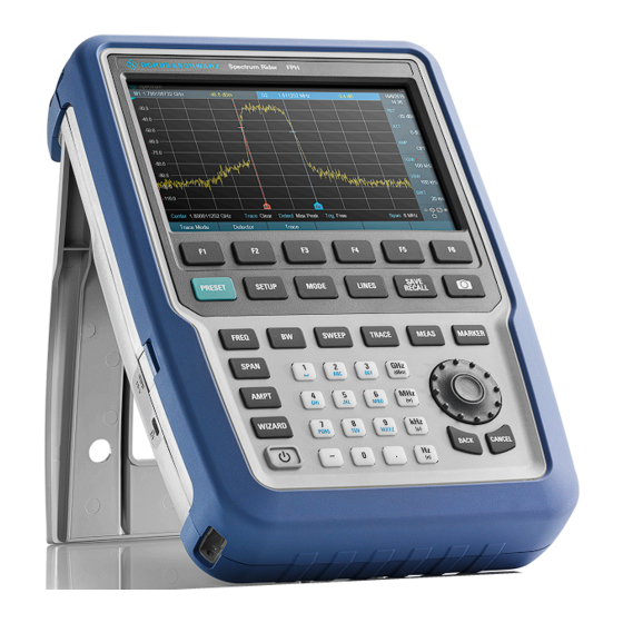
® Instrument tour R&S Spectrum Rider FPH Front view Front view Figure 6-1: Front panel of R&S Spectrum Rider RF input (N-type, PC 3.5 mm or PC 2.92 mm connector) BNC connectors Headphone jack USB ports RF output (N-type, PC 3.5 mm or PC 2.92 mm connector) Touch-sensitive screen area Softkey labels (on display) Softkey... -
Page 26: Top View
® Instrument tour R&S Spectrum Rider FPH Top view Instrument damage caused by cleaning agents Cleaning agents contain substances that may damage the instrument. For example, cleaning agents that contain a solvent may damage the front panel labeling, plastic parts, or the display. Never use cleaning agents such as solvents (thinners, acetone, etc.), acids, bases, or other substances. - Page 27 ® Instrument tour R&S Spectrum Rider FPH Top view Make sure not to overload the R&S Spectrum Rider when a DUT is connected. The maximum power that is permissible at the RF input is 20 dBm (or 100 mW). The RF input is protected from static discharges and voltage pulses by a limiting circuit.
- Page 28 ® Instrument tour R&S Spectrum Rider FPH Top view cate that the reference signal is supplied via external signal input. The label turns green when the reference signal is detected. The level of the reference signal must be larger than 0 dBm. If there is no refer- ence signal present at the BNC connector, the R&S Spectrum Rider displays an appropriate message.
-
Page 29: Left View
® Instrument tour R&S Spectrum Rider FPH Right view Left view DC port Kensington lock slot DC port The R&S Spectrum Rider is supplied with power by the AC/DC transformer power supply via the DC connector. You can also use the DC connector to charge the battery. -
Page 30: Rear View
® Instrument tour R&S Spectrum Rider FPH Touchscreen display LAN port RJ-45 connector to connect the instrument to a Local Area Network (LAN) and transfer data in both directions. It supports up to 100 Mbit/s. Rear view SD card slot The micro-SD card slot is located behind the battery compartment of the R&S Spectrum Rider. - Page 31 ® Instrument tour R&S Spectrum Rider FPH Touchscreen display Risk of touchscreen damage during operation The touchscreen may be damaged by inappropriate tools or excessive force. Observe the following instructions when operating or cleaning the touch- screen: ● Never touch the screen with ball point pens or other pointed objects with sharp edges.
-
Page 32: Title Bar
® Instrument tour R&S Spectrum Rider FPH Touchscreen display Measurement trace window Parameter view A touchscreen is a screen that is touch-sensitive, i.e. it reacts in a specified way when a particular element on the screen is tapped by a finger. Touchscreen gesture Special touchscreen features are provided to enhance user experience in using the instrument:... -
Page 33: Measurement Result View
® Instrument tour R&S Spectrum Rider FPH Touchscreen display ● Standard information such as measurement standard name and channel table name. 6.6.2 Measurement result view Special touchscreen gesture You can swipe vertically up or down in the "Measurement result view" to hide or unhide the measurement result view display. -
Page 34: Measurement Trace Window
® Instrument tour R&S Spectrum Rider FPH Touchscreen display Table 6-2: Highlighted marker Highlighted marker in the "Measurement Highlighted marker in the "Measurement result view" trace window" Note: There is a blue frame on the highlighted "M1" marker. For more information on marker measurement, see "Using markers"... -
Page 35: Parameter View
® Instrument tour R&S Spectrum Rider FPH Touchscreen display 6.6.4 Parameter view The "Parameter view" contains the important trace setting parameters for the spectrum measurement. It is located at the right side and bottom section of the layout . See Figure 6-2. -
Page 36: Configuration Overview
® Instrument tour R&S Spectrum Rider FPH Touchscreen display "ATT" Select "ATT" to display an entry box to config- ure the attenuation setting for the spectrum measurement. "PA" Depending on the instrument models, optional preamplifier such as R&S FPH-B22 / B23 / B24 / B25 / B26 is available for installation. - Page 37 ® Instrument tour R&S Spectrum Rider FPH Touchscreen display The "Config Overview" window is divided into six categories: Table 6-3: Corresponding dialog box of "Config Overview" window "Config Overview" block Corresponding dialog box Description Select "Input" to configure RF impedance. Select "Amplitude"...
- Page 38 ® Instrument tour R&S Spectrum Rider FPH Touchscreen display Select "Frequency" to config- ure the center frequency, fre- quency offset and span of the spectrum measurement. Select "Bandwidth" to config- ure resolution bandwidth, video bandwidth and sweep time for the spectrum mea- surement.
-
Page 39: On-Screen Keyboard
® Instrument tour R&S Spectrum Rider FPH Front panel keys On-screen keyboard The on-screen keyboard is an additional means of interacting with the instrument. It provides convenience of usage with the touchscreen input. Accessing the on-screen keyboard is only available for text-based entry, e.g. save or open a filename. -
Page 40: Screenshot Key
® Instrument tour R&S Spectrum Rider FPH Front panel keys 6.8.2 Screenshot key The screenshot key provides a quick way to capture screenshot of the current screen at anytime. For more information, see "Taking Screenshots" in the R&S Spectrum Rider user manual. -
Page 41: Function Keys
® Instrument tour R&S Spectrum Rider FPH Front panel keys SYSTEM keys Descriptions [PRESET] Resets the instrument to the default state. [SETUP] Provides basic instrument configuration functions: ● Reference frequency (external/internal) and hard- ware selection ● Date, time, display, audio and regional configuration ●... -
Page 42: Keypad
® Instrument tour R&S Spectrum Rider FPH Front panel keys FUNCTION keys Descriptions [AMPT] Sets the reference level, the displayed dynamic range, the RF attenuation and the unit for the level display. Sets the level offset and the input impedance. Activates the optional preamplifier. -
Page 43: Navigation Controls
® Instrument tour R&S Spectrum Rider FPH Front panel keys It contains the following keys: Type of key Description Alphanumeric Enter numbers and (special) characters in edit dialog boxes. keys Decimal point Inserts a decimal point "." at the cursor position. Sign key Changes the sign of a numeric parameter. -
Page 44: Managing Options
® Instrument tour R&S Spectrum Rider FPH Managing options The rotary knob has several functions: ● Increments (clockwise direction) or decrements (counter-clockwise direction) the instrument parameters at a defined step width in the case of a numeric entry ● Shifts markers, limit lines and display line on the screen ●... -
Page 45: Checking Options
® Instrument tour R&S Spectrum Rider FPH Managing options 4. Enter in the appropriate option key. 5. Confirm the entry with the rotary knob. If you have entered the correct code, the instrument displays a "installation successful" message. If incorrect code is entered, the instrument displays a "invalid key code!" mes- sage. - Page 46 ® Instrument tour R&S Spectrum Rider FPH Managing options The browser accesses the R&S License Manager. In this part of the R&S License Manager, you can install and activate licenses on the R&S Spectrum Rider. This page features three areas: ●...
-
Page 47: Configuring The R&S Spectrum Rider
® Instrument tour R&S Spectrum Rider FPH Configuring the R&S Spectrum Rider The browser accesses another part of the R&S License Manager. In this part of the license manager, you can manage licenses already installed on your R&S Spectrum Rider. This page features two areas: ●... -
Page 48: Configuring The Hardware
® Instrument tour R&S Spectrum Rider FPH Configuring the R&S Spectrum Rider 1. Press [SETUP] key. 2. Select "Instrument Setup" softkey. A corresponding dialog box to configure the instrument opens. 3. Select the item you want to modify. ● Configuring the hardware................48 ●... -
Page 49: Configuring Antennas
® Instrument tour R&S Spectrum Rider FPH Configuring the R&S Spectrum Rider Configuring the BNC connector You can use the BNC connectors for various applications. For more information on the supported applications, see "BNC connector" on page 27. 1. In the "Instrument Setup" dialog box, select the "BNC" item. A drop-down menu to select the BNC connector application opens. - Page 50 ® Instrument tour R&S Spectrum Rider FPH Configuring the R&S Spectrum Rider Enabling the antenna 1. In the "Instrument Setup" dialog box, select the "Antenna" menu item. A drop-down menu to select the antenna opens. 2. Select the required antenna. The R&S Spectrum Rider enables the selected antenna.
- Page 51 ® Instrument tour R&S Spectrum Rider FPH Configuring the R&S Spectrum Rider 2. Select "On" to enable the compass. The R&S Spectrum Rider shows the magnetic declination of your current posi- tion in the "Magnetic Declination" menu item when you turn on the compass. Showing compass information 1.
- Page 52 ® Instrument tour R&S Spectrum Rider FPH Configuring the R&S Spectrum Rider Calibrating the antenna If you need to know technical specification about the antenna, for example for service or support, you can get the necessary information from the "Antenna Service Menu" provided in the R&S Spectrum Rider. The "Antenna Service Menu"...
- Page 53 ® Instrument tour R&S Spectrum Rider FPH Configuring the R&S Spectrum Rider The R&S Spectrum Rider starts the calibration. For antenna calibration, it is necessary to move the antenna according to the direction as instructed on the screen. 4. When calibration completes, the R&S Spectrum Rider displays a "Calibration Successful"...
-
Page 54: Using The Gps Receiver
® Instrument tour R&S Spectrum Rider FPH Configuring the R&S Spectrum Rider 6.10.3 Using the GPS receiver The R&S Spectrum Rider can locate your exact position if you connect the GPS receiver (R&S HA-Z340, order number 1321.1392.02) to the USB connector. Getting Started 1321.0996.02 ─... - Page 55 ® Instrument tour R&S Spectrum Rider FPH Configuring the R&S Spectrum Rider Location to secure GPS receiver (R&S HA-Z340) Figure 6-3: Location of GPS receiver ● Tighten the knob screw supplied with the GPS receiver to the screw track at the back of R&S Spectrum Rider. ●...
- Page 56 ® Instrument tour R&S Spectrum Rider FPH Configuring the R&S Spectrum Rider Displaying GPS information 1. In the "Instrument Setup" dialog box, select the "Show GPS Information" item. A drop-down menu opens to turn the display of the GPS information on and off.
-
Page 57: Configuring Date And Time
® Instrument tour R&S Spectrum Rider FPH Configuring the R&S Spectrum Rider 2. Select the coordinate format from the drop-down menu. 6.10.4 Configuring date and time The R&S Spectrum Rider has an internal clock that can apply a date and time- stamp. -
Page 58: Selecting Regional Settings
® Instrument tour R&S Spectrum Rider FPH Configuring the R&S Spectrum Rider Selecting the time zone 1. In the "Instrument Setup" dialog box, select the "Time Zone" item. 2. Enter a positive or negative time offset relative to the system time with the numeric keys. -
Page 59: Configuring The Display
® Instrument tour R&S Spectrum Rider FPH Configuring the R&S Spectrum Rider 2. Select the desired language from the drop-down menu. 3. Reboot the device to activate the choice of selected language. Setting the date format The R&S Spectrum Rider provides two different formats to display the date. 1. - Page 60 ® Instrument tour R&S Spectrum Rider FPH Configuring the R&S Spectrum Rider The display of the R&S Spectrum Rider is a TFT color LCD display. The ideal brightness of the display depends on the intensity of the backlight. To strike a balance between battery operating time and screen display quality, set the backlight intensity to the minimum brightness needed.
- Page 61 ® Instrument tour R&S Spectrum Rider FPH Configuring the R&S Spectrum Rider 2. Select the color scheme from the drop-down menu. a) "Color" selects a color display. b) "Black & White" selects monochrome display. c) "Printer Friendly" inverts the colors. Adjusting the keyboard backlight 1.
-
Page 62: Configuring The Audio Output
® Instrument tour R&S Spectrum Rider FPH Configuring the R&S Spectrum Rider 3. Select "OFF" to deactivate the touchscreen interface. Note: If the touch interface is not activated, the On-screen keyboard is dis- abled. 6.10.7 Configuring the audio output The audio settings control the audio output of the system. Setting the key click volume The key click volume sets the volume of the sound that the R&S Spectrum Rider produces when you press a key or select a softkey. -
Page 63: Configuring Power Supply
® Instrument tour R&S Spectrum Rider FPH Configuring the R&S Spectrum Rider 2. Enter the volume you want with the numeric keys. The system beeper volume is a percentage from 0% to 100% with 100% being the loudest. 3. Confirm the entry with the rotary knob. Activating / Deactivating audio alert for power overload In case the R&S Spectrum Rider detects an overload at one of its inputs, you can configure the alert audible. - Page 64 ® Instrument tour R&S Spectrum Rider FPH Configuring the R&S Spectrum Rider Setting the battery low level The battery low level is a reminder that the remaining battery charge might be used up soon. When the battery low level is reached, the battery symbol in the title bar turns red and starts blinking.
-
Page 65: Internal Alignment
® Instrument tour R&S Spectrum Rider FPH Configuring the R&S Spectrum Rider 2. Select "On" to turn on the auto power up mode. On the next power up cycle, the R&S Spectrum Rider goes into the auto power up mode when supplying with an AC power. 6.10.9 Internal alignment R&S Spectrum Rider option R&S FPH-K35 (order number: 1321.1563.02) option is required to operate... - Page 66 ® Instrument tour R&S Spectrum Rider FPH Configuring the R&S Spectrum Rider 3. Select "Yes" to overwrite existing default alignment data and proceed to per- form alignment. The R&S Spectrum Rider displays the "Alignment" dialog. Depending on the selected alignment item, different input signal is required. Figure 6-4 Figure 6-5.
-
Page 67: Resetting The R&S Spectrum Rider
® Instrument tour R&S Spectrum Rider FPH Configuring the R&S Spectrum Rider 6.10.10 Resetting the R&S Spectrum Rider You can either preset the R&S Spectrum Rider or reset it to factory settings. Presetting the R&S Spectrum Rider The [PRESET] key resets the R&S Spectrum Rider to the default setup of the cur- rently active operating mode. -
Page 68: Connecting The R&S Spectrum Rider To A Pc
® Instrument tour R&S Spectrum Rider FPH Connecting the R&S Spectrum Rider to a PC The R&S Spectrum Rider initiates the reset procedure and shows a warning message box. 3. A corresponding dialog box opens for selection. ● Select "Yes" to perform the reset. During the reboot, it shows a corre- sponding message. -
Page 69: Lan Connection
® Instrument tour R&S Spectrum Rider FPH Connecting the R&S Spectrum Rider to a PC 6.11.1 LAN connection You can connect the R&S Spectrum Rider directly to the PC with a LAN cable. LAN port is located behind a protective cap on the right side of the R&S Spectrum Rider. - Page 70 ® Instrument tour R&S Spectrum Rider FPH Connecting the R&S Spectrum Rider to a PC 2. In the "Instrument Settings" dialog box, select the "Subnet Mask" item. 3. Enter the subnet mask of the PC with the numeric keys. After you have matched the subnet mask, you can define the IP address. When both devices are in the same subnet, the first three digits of the IP address are usually the same.
- Page 71 ® Instrument tour R&S Spectrum Rider FPH Connecting the R&S Spectrum Rider to a PC 3. Confirm the entry with the rotary knob. 4. Enter the IP address of the PC with the numeric keys. Configuring the R&S InstrumentView software package 1.
- Page 72 ® Instrument tour R&S Spectrum Rider FPH Connecting the R&S Spectrum Rider to a PC 5. Specify a name and the IP address for the new network connection. 6. Select "Local Area Connection" for the "Network Adapter". 7. Confirm the entry with the "OK" button to add the new instrument to the con- nection manager list.
- Page 73 ® Instrument tour R&S Spectrum Rider FPH Connecting the R&S Spectrum Rider to a PC Connecting the R&S Spectrum Rider in an existing LAN You can either get the R&S Spectrum Rider IP address automatically from the DHCP server or manually assign a fixed address. With manual allocation, a fixed IP address and subnet mask must be assigned to the R&S Spectrum Rider as described in Chapter 6.11.1, "LAN...
-
Page 74: Usb Connection
® Instrument tour R&S Spectrum Rider FPH Connecting the R&S Spectrum Rider to a PC The DHCP is off by default. Turn it on like this: 1. In the "Instrument Setup" dialog box, select the "DHCP" item. 2. Select "DHCP" to "On" to activate the DHCP. The R&S Spectrum Rider is now allocated an IP address and the subnet mask by the DHCP server. - Page 75 ® Instrument tour R&S Spectrum Rider FPH Connecting the R&S Spectrum Rider to a PC Figure 6-6: USB connection Getting Started 1321.0996.02 ─ 12...
-
Page 76: Trying Out The Instrument
® Trying out the instrument R&S Spectrum Rider FPH Using the spectrum analyzer Trying out the instrument This chapter provides a short overview of the first steps of the measurements you can perform with the R&S Spectrum Rider. ● Using the spectrum analyzer................76 ●... -
Page 77: Using The Preamplifier
® Trying out the instrument R&S Spectrum Rider FPH Using the spectrum analyzer You can also set the attenuation manually. TheR&S Spectrum Rider provides attenuation in the range from 0 dB to 40 dB in 5 dB steps. 4. Press [AMPT] key. 5. -
Page 78: Measuring Cw Signals
® Trying out the instrument R&S Spectrum Rider FPH Using the spectrum analyzer gain of the amplifier is in the range from 15 dB to 20 dB and increases the sensi- tivity by 10 dB to 15 dB. In the signal path, the preamplifier comes after the input protection circuit and before the RF attenuator of the R&S Spectrum Rider to provide excellent sensitiv- ity when the preamplifier is switched on. - Page 79 ® Trying out the instrument R&S Spectrum Rider FPH Using the spectrum analyzer Test setup Connect the RF output of the signal generator to the RF input of the R&S Spec- trum Rider. Signal generator settings: ● Frequency: 500 MHz ●...
- Page 80 ® Trying out the instrument R&S Spectrum Rider FPH Using the spectrum analyzer Setting the reference level The level at the top of the measurement diagram is called the reference level. To obtain the best dynamic range from the R&S Spectrum Rider, you should use its full level range.
- Page 81 ® Trying out the instrument R&S Spectrum Rider FPH Using the spectrum analyzer ► Press [MARKER] key. The R&S Spectrum Rider activates a marker and puts it on the maximum value on the trace. The coordinates of the marker are shown in a table above the measurement diagram.
-
Page 82: Measuring Harmonics
® Trying out the instrument R&S Spectrum Rider FPH Using the spectrum analyzer The measurement result of the frequency counter is displayed at the "Measure- ment result view". When the frequency counter is active, the highest resolution of the frequency readout that can be achieve is 0.0001 Hz. The accuracy is deter- mined by the internal reference frequency which is far more exact than the pixel- oriented marker readout. - Page 83 ® Trying out the instrument R&S Spectrum Rider FPH Using the spectrum analyzer Detecting harmonics 1. Press [PRESET] key. The R&S Spectrum Rider is reset to its default state. After the preset, the R&S Spectrum Rider displays the frequency spectrum over its full frequency span.
-
Page 84: Using A Power Sensor
® Trying out the instrument R&S Spectrum Rider FPH Using a power sensor To measure the harmonic ratio, set the marker on the signal and a delta marker on the second harmonic. 9. Press [MARKER] key. The R&S Spectrum Rider sets a marker on the trace maximum. The trace maximum corresponds to the signal. -
Page 85: Measuring The Power With A Power Sensor
® Trying out the instrument R&S Spectrum Rider FPH Using a power sensor For highly accurate power measurements, you can connect one of the power sen- sors that are supported by the R&S Spectrum Rider. For a list of R&S Spectrum Rider supported power sensors, see the datasheet of the R&S Spectrum Rider. - Page 86 ® Trying out the instrument R&S Spectrum Rider FPH Using a power sensor 1 = Supported power sensor (e.g R&S FSH-Z1, R&S NRP-Z11) 2 = Power sensor connector (DUT) 3 = USB binder adaptor (R&S FSH-Z101) 4 = USB port connector Measuring the power 1.
- Page 87 ® Trying out the instrument R&S Spectrum Rider FPH Using a power sensor 4. Wait for the zeroing process to finish. After zeroing, the R&S Spectrum Rider displays the message "Power sensor zero done" and again shows the power sensor softkey menu. 5.
-
Page 88: Measuring Power And Return Loss
® Trying out the instrument R&S Spectrum Rider FPH Using a power sensor 2. Enter the frequency of the signal. 3. Confirm the entry with one of the unit keys. The R&S Spectrum Rider transfers the new frequency to the power sensor which then corrects the measured power readings. - Page 89 ® Trying out the instrument R&S Spectrum Rider FPH Using a power sensor the FSH-Z144 adaptor cable is needed. Insert the directional power sensor between the source and the load. The power sensors for the R&S Spectrum Rider have an asymmetrical design. Hence, you have to insert them into the test setup in such a way that the "For- ward"...
-
Page 90: Saving And Recalling Results And Settings
® Trying out the instrument R&S Spectrum Rider FPH Saving and recalling results and settings ► Connect the R&S FSH-Z14 or R&S FSH-Z44 between the source and the load. The R&S Spectrum Rider displays the measured forward power in dBm and the SWR of the load. - Page 91 ® Trying out the instrument R&S Spectrum Rider FPH Saving and recalling results and settings The R&S Spectrum Rider can store measurement results and settings in the internal memory, removable micro-SD card or on a USB flash drive via the USB interface.
-
Page 92: Contacting Customer Support
® Contacting customer support R&S Spectrum Rider FPH Contacting customer support Technical support – where and when you need it For quick, expert help with any Rohde & Schwarz product, contact our customer support center. A team of highly qualified engineers provides support and works with you to find a solution to your query on any aspect of the operation, program- ming or applications of Rohde &... -
Page 93: Index
® Index R&S Spectrum Rider FPH Index AC adapter ..........16 Frequency ..........78 Accessory detection ........ 48 Front panel keys ........39 Antenna Function keys .......... 41 Configuring ......... 48 Application cards ........10 Application notes ........10 Getting started ........... 9 Attenuation .......... - Page 94 ® Index R&S Spectrum Rider FPH Package contents ........14 Unpacking and checking the instrument . 13 Positioning USB connection with R&S Spectrum Rider Support ..........14 ..............74 Power key ..........39 USB port ..........28 Power overload beep ......63 User interface ..........
Need help?
Do you have a question about the FPH-26G and is the answer not in the manual?
Questions and answers