Table of Contents
Advertisement
Quick Links
Advertisement
Table of Contents

Related Manuals for Rohde & Schwarz FPL1003-P4


Summary of Contents for Rohde & Schwarz FPL1003-P4
- Page 1 ® R&S FPL1000 Spectrum Analyzer Getting Started (=G@22) 1323160202...
- Page 2 ® This manual applies to the following R&S FPL1000 models with firmware version 1.60 and later: ● R&S ® FPL1003 (1304.0004K03) - FPL1000 with maximum frequency 3 GHz ● R&S ® FPL1007 (1304.0004K07) - FPL1000 with maximum frequency 7.5 GHz In addition to the base unit, the following options are described: ●...
-
Page 3: Table Of Contents
® Contents R&S FPL1000 Contents 1 Safety and Regulatory Information........7 1.1 Safety Instructions................7 1.2 Labels on R&S FPL1000..............11 1.3 Korea Certification Class A..............12 2 Documentation-Overview........... 13 2.1 Getting Started Manual...............13 2.2 User Manuals and Help..............13 2.3 Service Manual..................14 2.4 Instrument Security Procedures............ - Page 4 ® Contents R&S FPL1000 4.9 Connecting an External Monitor............27 4.10 Windows Operating System...............29 4.11 Logging On..................30 4.12 Checking the Supplied Options............32 4.13 Performing a Self-Alignment............. 32 4.14 Considerations for Test Setup............33 5 Instrument Tour..............34 5.1 Front Panel View................. 34 5.2 Rear Panel View..................
- Page 5 ® Contents R&S FPL1000 8.1 Collecting Information for Support........... 91 8.2 Contacting Customer Support............93 Index..................95 Getting Started 1323.1602.02 ─ 08...
- Page 6 ® Contents R&S FPL1000 Getting Started 1323.1602.02 ─ 08...
-
Page 7: Safety And Regulatory Information
® Safety and Regulatory Information R&S FPL1000 Safety Instructions Safety and Regulatory Information The product documentation helps you use the product safely and efficiently. Fol- low the instructions provided here and in the Chapter 1.1, "Safety Instructions", on page 7. Intended use The product is intended for the development, production and verification of elec- tronic components and devices in industrial, administrative, and laboratory envi-... - Page 8 ® Safety and Regulatory Information R&S FPL1000 Safety Instructions If any part of the product is damaged or broken, stop using the product. Never open the casing of the product. Only service personnel authorized by Rohde & Schwarz are allowed to repair the product. Contact Rohde & Schwarz customer service at http://www.customersupport.rohde-schwarz.com.
- Page 9 ® Safety and Regulatory Information R&S FPL1000 Safety Instructions Connecting to power The product is an overvoltage category II product and has to be connected to a fixed installation used to supply energy-consuming equipment such as household appliances and similar loads. Be aware that electrically powered products have risks, such as electric shock, fire, personal injury or even death.
- Page 10 ® Safety and Regulatory Information R&S FPL1000 Safety Instructions Potential hazard Read the product documentation to avoid personal injury or product damage. Electrical hazard Indicates live parts. Risk of electric shock, fire, personal injury or even death. Hot surface Do not touch. Risk of skin burns. Risk of fire. Protective conductor terminal Connect this terminal to a grounded external conductor or to protective ground.
-
Page 11: Labels On R&S Fpl1000
® Safety and Regulatory Information R&S FPL1000 Labels on R&S FPL1000 ● Dispose of batteries separately from normal household waste as specified by the local waste disposal agency. If you disregard these rules, you risk serious personal injury or even death due to explosion, fire or hazardous chemical substances. -
Page 12: Korea Certification Class A
® Safety and Regulatory Information R&S FPL1000 Korea Certification Class A Korea Certification Class A 이 기기는 업무용(A급) 전자파 적합기기로서 판매자 또는 사용자는 이 점을 주의하 시기 바라며, 가정외의 지역에서 사용하는 것을 목적으로 합니다. Getting Started 1323.1602.02 ─ 08... -
Page 13: Documentation-Overview
® Documentation-Overview R&S FPL1000 User Manuals and Help Documentation-Overview This section provides an overview of the R&S FPL1000 user documentation. Unless specified otherwise, you find the documents on the R&S FPL1000 product page at: www.rohde-schwarz.com/manual/FPL1000 Getting Started Manual Introduces the R&S FPL1000 and describes how to set up and start working with the product. -
Page 14: Service Manual
® Documentation-Overview R&S FPL1000 Data Sheets and Brochures All user manuals are also available for download or for immediate display on the Internet. Service Manual Describes the performance test for checking the rated specifications, module replacement and repair, firmware update, troubleshooting and fault elimination, and contains mechanical drawings and spare part lists. -
Page 15: Release Notes And Open Source Acknowledgment (Osa)
® Documentation-Overview R&S FPL1000 Calibration Certificate Release Notes and Open Source Acknowledg- ment (OSA) The release notes list new features, improvements and known issues of the cur- rent firmware version, and describe the firmware installation. The open-source acknowledgment document provides verbatim license texts of the used open source software. -
Page 16: Key Features
® Key Features R&S FPL1000 Key Features The R&S FPL1000 sets standards in RF performance and usability. Outstanding key features are: One instrument for multiple applications ● Spectrum analysis ● Signal analysis of analog and digitally modulated signals ● Power measurements with power sensors ●... -
Page 17: Preparing For Use
® Preparing for Use R&S FPL1000 Unpacking and Checking Preparing for Use This chapter describes the basic steps to be taken when setting up the product for the first time. ● Lifting and Carrying..................17 ● Unpacking and Checking................17 ●... -
Page 18: Choosing The Operating Site
® Preparing for Use R&S FPL1000 Setting Up the R&S FPL1000 4. Check the equipment for damage. If the delivery is incomplete or equipment is damaged, contact Rohde & Schwarz. Choosing the Operating Site Specific operating conditions ensure accurate measurements and avoid damage to the product and connected devices. - Page 19 ® Preparing for Use R&S FPL1000 Setting Up the R&S FPL1000 4.4.1 Placing the R&S FPL1000 on a Bench Top To place the product on a bench top 1. Place the product on a stable, flat and level surface. Ensure that the surface can support the weight of the product.
- Page 20 ® Preparing for Use R&S FPL1000 Setting Up the R&S FPL1000 2. NOTICE! Insufficient airflow can cause overheating and damage the product. Design and implement an efficient ventilation concept for the rack. To mount the R&S FPL1000 in a rack 1.
-
Page 21: Connecting To Power
® Preparing for Use R&S FPL1000 Connecting to Power ► Inspect the carrying bag for wear and tear before placing the instrument in it. For details on optional accessories, see the R&S FPL1000 data sheet. Connecting to Power There are various options to supply power to the R&S FPL1000. ●... - Page 22 ® Preparing for Use R&S FPL1000 Connecting to Power To connect the AC power 1. Plug the AC power cable into the AC power connector on the rear panel of the instrument. Only use the AC power cable delivered with the R&S FPL1000. 2.
- Page 23 ® Preparing for Use R&S FPL1000 Connecting to Power 4.5.3 Optional Battery Pack (R&S FPL1-B31) As an alternative to the fixed AC or DC power supply, the R&S FPL1000 also allows for battery operation. The R&S FPL1-B31 Battery pack" option comprises two Li-ion batteries and an internal charger.
-
Page 24: Switching On Or Off
® Preparing for Use R&S FPL1000 Switching On or Off Spare battery pack (R&S FPL1-Z4) In addition to the internal battery pack (option R&S FPL1-B31), spare batteries are available for the R&S FPL1000. The spare battery pack R&S FPL1-Z4 com- prises two additional Li-ion batteries. -
Page 25: Connecting To Lan
® Preparing for Use R&S FPL1000 Connecting to LAN To shut down the product The product is in the ready state. ► Press the Power key. The operating system shuts down. The LED changes to orange. To disconnect from power The R&S FPL1000 is in the standby state. -
Page 26: Connecting A Keyboard
® Preparing for Use R&S FPL1000 Connecting a Keyboard The default instrument name is <Type><variant>-<serial_number>, for example, FPL1003-123456. For information on determining the serial number, see Chapter 5.2.14, "Device ID", on page 47. For more information on LAN configuration, see the R&S FPL1000 user manual. 4.7.1 Virus Protection Take appropriate steps to protect your instruments from infection. -
Page 27: Connecting An External Monitor
® Preparing for Use R&S FPL1000 Connecting an External Monitor 2. Select "Start > Settings > Time & language > Region & language > Add a lan- guage" . Connecting an External Monitor You can connect an external monitor (or projector) to the "DVI" connector on the rear panel of the R&S FPL1000 (see also Chapter 5.2.6, "DVI",... - Page 28 ® Preparing for Use R&S FPL1000 Connecting an External Monitor 5. If necessary, change the screen resolution. Consider the information in the note above. 6. Select the instrument for display: ● "Display 1": internal monitor only ● "Display 2": external monitor only ●...
-
Page 29: Windows Operating System
® Preparing for Use R&S FPL1000 Windows Operating System To fix the mapping between touchscreen and display, connect an external monitor to the R&S FPL1000 and proceed as follows: 1. Select [Setup] > "Display" > "Configure Monitor" > "Display Switch" to bring up the Windows 10 "PROJECT"... -
Page 30: Logging On
® Preparing for Use R&S FPL1000 Logging On You can install additional software on the instrument; however, additional soft- ware can impair instrument function. Thus, run only programs that Rohde & Schwarz has tested for compatibility with the instrument software. The following program packages have been tested: ●... - Page 31 ® Preparing for Use R&S FPL1000 Logging On ● "Instrument": a standard user account with limited access ● "Administrator": an administrator account with unrestricted access to the computer/domain Some administrative tasks require administrator rights (e.g. the configuration of a LAN network). Refer to the description of the basic instrument Setup ([Setup] menu) to find out which functions are affected.
-
Page 32: Checking The Supplied Options
® Preparing for Use R&S FPL1000 Performing a Self-Alignment 4.12 Checking the Supplied Options The instrument can be equipped with both hardware and firmware options. To check whether the installed options correspond to the options indicated on the delivery note, proceed as follows. 1. -
Page 33: Considerations For Test Setup
® Preparing for Use R&S FPL1000 Considerations for Test Setup To display the alignment results again later ● Press the [Setup] key. ● Press the "Alignment" softkey. 4.14 Considerations for Test Setup Cable selection and electromagnetic interference (EMI) Electromagnetic interference (EMI) can affect the measurement results. To suppress electromagnetic radiation during operation: ●... -
Page 34: Instrument Tour
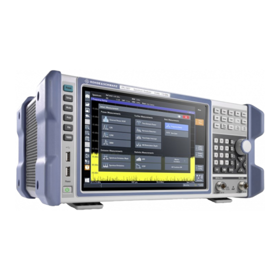
® Instrument Tour R&S FPL1000 Front Panel View Instrument Tour Front Panel View This chapter describes the front panel, including all function keys and connectors. Figure 5-1: Front panel view of R&S FPL1000 1 = Power key 2 = USB (2.0) connectors 3 = System keys 4 = Touchscreen 5 = Function keys... - Page 35 ® Instrument Tour R&S FPL1000 Front Panel View ing an alternative means of user interaction for quick and easy handling of the instrument. Figure 5-2: Touchscreen elements 1 = Toolbar with standard application functions, e.g. print, save/open file etc. 2 = Tabs for individual channel setups 3 = Softkeys for function access 4 = Channel Setup bar for firmware and measurement settings 5 = Window title bar with diagram-specific (trace) information...
- Page 36 ® Instrument Tour R&S FPL1000 Front Panel View ● Zooming into a diagram ● Selecting a new evaluation method ● Scrolling through a result list or table ● Saving or printing results and settings To imitate a right-click by mouse using the touchscreen, for example to open a context-sensitive menu for a specific item, press the screen for about 1 second.
- Page 37 ® Instrument Tour R&S FPL1000 Front Panel View Table 5-1: System keys System key Assigned functions [Preset] Resets the instrument to the default state. [Setup] Provides basic instrument configuration functions, e.g.: ● Reference frequency (external/internal) ● Date, time, display configuration ●...
- Page 38 ® Instrument Tour R&S FPL1000 Front Panel View Function key Assigned functions [Sweep] Sets the sweep time and the number of measurement points Selects continuous measurement or single measurement [Trace] Configures the graphical analysis of the measurement data [Meas] Provides the measurement functions: Measurement of multicarrier adjacent channel power (Ch Power ACLR) Carrier to noise spacing (C/N C/N...
- Page 39 ® Instrument Tour R&S FPL1000 Front Panel View 5.1.6 Keypad The keypad is used to enter numeric parameters, including the corresponding units. It contains the following keys: Table 5-3: Keys on the keypad Type of key Description Decimal point Inserts a decimal point "." at the cursor position. Sign key Changes the sign of a numeric parameter.
- Page 40 ® Instrument Tour R&S FPL1000 Front Panel View Navigating in tables The easiest way to navigate within tables (both in result tables and configu- ration tables) is to scroll through the entries with your finger on the touch- screen. 5.1.7.1 Rotary Knob The rotary knob has several functions: ●...
-
Page 41: Rear Panel View
® Instrument Tour R&S FPL1000 Rear Panel View ● In windows or dialog boxes with horizontal scroll bar, move the scroll bar. RF INPUT 50 Ω 5.1.8 Provides RF input from a connected device under test (DUT) to the R&S FPL1000, which is then analyzed in an RF measurement. Connect the DUT to the "RF Input"... - Page 42 ® Instrument Tour R&S FPL1000 Rear Panel View 14 15 Figure 5-3: Rear panel view 1+2 = Removable, rechargeable Li-ion batteries = DC power connector = AC power supply connection and main power switch with fuse = GPIB (IEC 625) interface = Reference clock connectors = Trigger input connector = "DVI"...
- Page 43 ® Instrument Tour R&S FPL1000 Rear Panel View For safety information concerning batteries, see "Handling batteries safely" on page 10. As an alternative, a DC power supply connector (option R&S FPL1-B30) is availa- ble. DC power supplies from +12 V to +24 V and from 13 A to 6.5 A can be used. Connect the connector according to the following diagram: Description Plus...
- Page 44 ® Instrument Tour R&S FPL1000 Rear Panel View For more details, refer to "Setting Up Remote Control" in the user manual. 5.2.4 Ref. In / Ref. Out The Ref. In connectors are used to provide an external reference signal to the R&S FPL1000.
- Page 45 ® Instrument Tour R&S FPL1000 Rear Panel View The assignment of the RJ-45 connector supports twisted-pair category 5 UTP/STP cables in a star configuration (UTP stands for unshielded twisted pair, and STP for shielded twisted pair). Provided the network administrator has assigned you the appropriate rights and adapted the Windows firewall configuration, you can use the interface, for exam- ple: ●...
- Page 46 ® Instrument Tour R&S FPL1000 Rear Panel View Short-circuit hazard Always observe the designated pin assignment. A short-circuit can damage the port. Table 5-4: Pin assignment for optional AUX port Signal Description Ground not used for spectrum analysis Ground not used for spectrum analysis Ground not used for spectrum analysis Ground...
- Page 47 ® Instrument Tour R&S FPL1000 Rear Panel View 5.2.11 IF/Video Output The female BNC connector can be used for various outputs in the Spectrum application: ● Intermediate frequency (IF) output of approximately 20 MHz ● Video output (1V) Which output is provided is defined in the software ("Overview" > "Output"). This connector is only available if the R&S FPL1-B5 option is installed.
- Page 48 ® Instrument Tour R&S FPL1000 Rear Panel View It consists of the device order number and a serial number. The serial number is used to define the default instrument name, which is: <Type><variant>-<serial_number> For example, FPL1003-123456. The instrument name is required to establish a connection to the instrument in a LAN.
-
Page 49: Trying Out The Instrument
® Trying Out the Instrument R&S FPL1000 Measuring a Basic Signal Trying Out the Instrument This chapter introduces the most important functions and settings of the R&S FPL1000 step by step. The complete description of the functionality and its usage is given in the R&S FPL1000 User Manual. Basic instrument operation is described in Chapter 7, "Operating the Instrument",... - Page 50 ® Trying Out the Instrument R&S FPL1000 Measuring a Basic Signal 6. Close the dialog box. The calibration signal is now sent to the RF input of the R&S FPL1000. By default, a continuous frequency sweep is performed, so that the spectrum of the calibration signal is now displayed in the standard level versus frequency diagram.
-
Page 51: Displaying A Spectrogram
® Trying Out the Instrument R&S FPL1000 Displaying a Spectrogram b) Tap the "Frequency" button. c) In the "Center" field, enter 50 on the number pad on the front panel. d) Press the "MHz" key next to the number pad. 2. - Page 52 ® Trying Out the Instrument R&S FPL1000 Displaying a Spectrogram 2. Tap the "Display Config" button. The SmartGrid mode is activated, and the evaluation bar with the available evaluation methods is displayed. Drag the "Spectrogram" icon from the evaluation bar to the diagram area. The blue area indicates that the new diagram would replace the previous spectrum display.
-
Page 53: Activating Additional Measurement Channels
® Trying Out the Instrument R&S FPL1000 Activating Additional Measurement Channels 5. Close the "Overview". You see the spectrogram compared to the standard spectrum display. Since the calibration signal does not change over time, the color of the frequency levels does not change over time, i.e. vertically. The legend at the top of the spectrogram window describes the power levels the colors represent. - Page 54 ® Trying Out the Instrument R&S FPL1000 Activating Additional Measurement Channels 2. On the "New Channel Setup" tab of the "Mode" dialog box, tap the "Spectrum" button. Figure 6-5: Adding a new measurement channel 3. Change the frequency range for this spectrum display: In the "Frequency"...
- Page 55 ® Trying Out the Instrument R&S FPL1000 Activating Additional Measurement Channels Figure 6-6: Frequency spectrum of the calibration signal with a larger span 4. Repeat the previous steps to activate a third Spectrum window. 5. Change the frequency range for this spectrum display: In the "Frequency"...
- Page 56 ® Trying Out the Instrument R&S FPL1000 Activating Additional Measurement Channels Figure 6-7: Time domain display of the calibration signal 7. Create a new measurement channel for I/Q analysis: a) Press the [Mode] key. b) Tap the "IQ Analyzer" button to activate a measurement channel for the I/Q Analyzer application.
- Page 57 ® Trying Out the Instrument R&S FPL1000 Activating Additional Measurement Channels d) Drag the "Real/Imag (I/Q)" icon from the evaluation bar to the SmartGrid to replace the default "Magnitude" display. Figure 6-8: Inserting a Real/Imag diagram for I/Q analysis e) Close the SmartGrid mode. The "IQ Analyzer"...
-
Page 58: Performing Sequential Measurements
® Trying Out the Instrument R&S FPL1000 Performing Sequential Measurements Figure 6-9: The "MultiView" tab Performing Sequential Measurements Although only one measurement can be performed at any one time, the measure- ments configured in the active channel setups can be performed sequentially, that means: one after the other, automatically, either once or continuously. -
Page 59: Setting And Moving A Marker
® Trying Out the Instrument R&S FPL1000 Setting and Moving a Marker Figure 6-10: "MultiView" tab with active Sequencer Figure 6-10, the "Spectrum 2" measurement is currently active (indicated by the "channel active" icon in the tab label). 3. Stop the Sequencer by tapping the "Sequencer" softkey again. Setting and Moving a Marker Markers are useful to determine the position of particular effects in the trace. - Page 60 ® Trying Out the Instrument R&S FPL1000 Setting and Moving a Marker 3. Double-tap the spectrum window to maximize it, as we currently do not need the spectrogram display. 4. Press the [Run Single] key on the front panel to perform a single sweep so we have a fixed trace to set a marker on.
-
Page 61: Displaying A Marker Peak List
® Trying Out the Instrument R&S FPL1000 Displaying a Marker Peak List Displaying a Marker Peak List The marker peak list determines the frequencies and levels of peaks in the spec- trum automatically. We will display a marker peak list for the "Spectrum 2" mea- surement channel. -
Page 62: Zooming Into The Display
® Trying Out the Instrument R&S FPL1000 Zooming into the Display 6. To obtain a more conclusive peak list that does not contain noise peaks, for example, define a threshold that is higher than the noise floor: a) Press the [Mkr] key on the front panel. b) Tap the "Marker Config"... - Page 63 ® Trying Out the Instrument R&S FPL1000 Zooming into the Display 1. Tap the "Multiple Zoom" icon in the toolbar. The icon is highlighted to indicate that multiple zoom mode is active. 2. Tap the diagram near the first peak and drag your finger to the opposite corner of the zoom area.
- Page 64 ® Trying Out the Instrument R&S FPL1000 Zooming into the Display the results, we will increase the number of sweep points from the default 1001 to 32001. a) Press the [Sweep] key on the front panel. b) Tap the "Sweep Config" softkey in the "Sweep" menu. c) In the "Sweep Points"...
- Page 65 ® Trying Out the Instrument R&S FPL1000 Zooming into the Display 4. Tap the "Multiple Zoom" icon in the toolbar again and define a zoom area around markers M2, M3 and M4. Figure 6-15: Multiple zoom windows 5. Tap the "Multiple Zoom" icon in the toolbar again and define a zoom area around marker M5.
-
Page 66: Saving Settings
® Trying Out the Instrument R&S FPL1000 Saving Settings Figure 6-16: Enlarged zoom window Saving Settings To restore the results of our measurements later, we will store the instrument set- tings to a file. To save the instrument settings to a file 1. - Page 67 ® Trying Out the Instrument R&S FPL1000 Saving Settings Keep the default "File Type" setting "Instrument with all Channel Setups" to store the configuration of all channel setups. Figure 6-17: Saving the instrument settings to a file 4. Tap the "Save" button. The file MyMultiViewSetup.dfl is stored in the default directory C:\Users\Public\Documents\Rohde-Schwarz\Analyzer\Save.
-
Page 68: Printing And Saving Results
® Trying Out the Instrument R&S FPL1000 Printing and Saving Results 2. Tap the "Load" icon in the toolbar. 3. In the "Load" dialog box, select the MyMultiViewSetup.dfl file in the default directory C:\Users\Public\Documents\Rohde-Schwarz\Analyzer\Save. 4. Tap the "Load" button. All instrument settings are restored and the display should resemble the instrument display right before the settings were stored. - Page 69 ® Trying Out the Instrument R&S FPL1000 Printing and Saving Results 2. In the "Save Hardcopy as" > "Portable Network Graphics (PNG)" dialog box, enter a file name, e.g. MyMultiViewDisplay. The screenshot is stored to MyMultiViewDisplay.png. Getting Started 1323.1602.02 ─ 08...
-
Page 70: Operating The Instrument
® Operating the Instrument R&S FPL1000 Understanding the Display Information - Spectrum Mode Operating the Instrument This chapter provides an overview on how to work with the R&S FPL1000. Remote control In addition to working with the R&S FPL1000 interactively, located directly at the instrument, it is also possible to operate and control it from a remote PC. - Page 71 ® Operating the Instrument R&S FPL1000 Understanding the Display Information - Spectrum Mode = Channel bar for firmware and measurement settings 2+3 = Window title bar with diagram-specific (trace) information = Diagram area with marker information = Diagram footer with diagram-specific information, depending on measurement application = Instrument status bar with error messages and date/time display Hiding elements in the display You can hide some of the elements in the display, for example the status...
- Page 72 ® Operating the Instrument R&S FPL1000 Understanding the Display Information - Spectrum Mode ● Frequency and Span Information in Diagram Footer........77 ● Instrument and Status Information..............78 ● Error Information..................... 78 7.1.1 Channel Setup Bar Using the R&S FPL1000 you can handle several different measurement tasks (channels) at the same time (although they can only be performed asynchro- nously).
- Page 73 ® Operating the Instrument R&S FPL1000 Understanding the Display Information - Spectrum Mode Icons in the channel bar yellow star icon on the tab label (sometimes referred to as a "dirty flag") indicates that invalid or inconsistent data is displayed, that is: the trace no longer matches the displayed instrument settings.
- Page 74 ® Operating the Instrument R&S FPL1000 Understanding the Display Information - Spectrum Mode Mode Indicates which sweep mode type is used: ● "Auto FFT": automatically selected FFT sweep mode ● "Auto sweep": automatically selected swept sweep mode Pwr.Swp Indicates the power sweep range for power sweep measurements using an optional internal tracking generator Icons for individual settings A bullet next to the setting indicates that user-defined settings are used, not auto-...
- Page 75 ® Operating the Instrument R&S FPL1000 Understanding the Display Information - Spectrum Mode The frequency sweep is controlled via the "TRIGGER INPUT" connector. The specified transducer factor is activated. 75 Ω The input impedance of the instrument is set to 75 Ω. A frequency offset ≠...
- Page 76 ® Operating the Instrument R&S FPL1000 Understanding the Display Information - Spectrum Mode (3) Detector Selected detector: AUTOPEAK detector MAX PEAK detector MIN PEAK detector SAMPLE detector AVERAGE detector RMS detector (4) Trace Mode Sweep mode: Clrw CLEAR/WRITE MAX HOLD MIN HOLD AVERAGE (Lin/Log/Pwr) View...
- Page 77 ® Operating the Instrument R&S FPL1000 Understanding the Display Information - Spectrum Mode "Type" Marker type: N (normal), D (delta), T (temporary, internal), PWR (power sensor) "Ref" Reference (for delta markers) "Trc" Trace to which the marker is assigned "X-value" X-value of the marker "Y-Value"...
- Page 78 ® Operating the Instrument R&S FPL1000 Understanding the Display Information - Spectrum Mode 7.1.5 Instrument and Status Information Global instrument settings and functions, the instrument status and any irregulari- ties are indicated in the status bar beneath the diagram. In the MultiView tab, the status bar always displays the information for the cur- rently selected measurement.
-
Page 79: Accessing The Functionality
® Operating the Instrument R&S FPL1000 Accessing the Functionality Table 7-3: Status bar information - color coding Color Type Description Error An error occurred at the start or during a measurement, e.g. due to missing data or wrong settings, so that the measurement cannot be started or completed correctly. - Page 80 ® Operating the Instrument R&S FPL1000 Accessing the Functionality ● Icons on the tool bar in the touchscreen ● Displayed setting on the touchscreen 7.2.1 Toolbar Functions Standard functions can be performed via the icons in the toolbar at the top of the screen.
- Page 81 ® Operating the Instrument R&S FPL1000 Accessing the Functionality Report Generator Displays the "Report" menu to configure a report. Undo Reverts last operation, i.e. the status before the previous action is retrieved. The undo function is useful, for example, if you are performing a zero span mea- surement with several markers and a limit line defined and accidentally select a different measurement.
- Page 82 ® Operating the Instrument R&S FPL1000 Accessing the Functionality Help (+ Select) Allows you to select an object for which context-specific help is displayed Chapter 7.5, "Getting Help", on page 89 Help Displays context-sensitive help topic for the most recently selected ele- ment Chapter 7.5, "Getting Help",...
- Page 83 ® Operating the Instrument R&S FPL1000 Accessing the Functionality 7.2.3 Context Menus Several items in the diagram area have context menus (for example markers, traces or the channel bar). If you right-click on one of these items (or tap it for about 1 second), a menu is displayed which contains the same functions as the corresponding softkey.
-
Page 84: Entering Data
® Operating the Instrument R&S FPL1000 Entering Data The on-screen keyboard display can be switched on and off as desired using the "On-Screen Keyboard" function key beneath the screen. When you press this key, the display switches between the following options: ●... - Page 85 ® Operating the Instrument R&S FPL1000 Entering Data Transparent dialog boxes You can change the transparency of the dialog boxes to see the results in the windows behind the dialog box. Thus, you can see the effects that the changes you make to the settings have on the results immediately. To change the transparency, select the transparency icon at the top of the dialog box.
-
Page 86: Touchscreen Gestures
® Operating the Instrument R&S FPL1000 Touchscreen Gestures Correcting an entry 1. Using the arrow keys, move the cursor to the right of the entry you want to delete. 2. Press the [Backspace] key. The entry to the left of the cursor is deleted. 3. - Page 87 ® Operating the Instrument R&S FPL1000 Touchscreen Gestures Figure 7-1: Tapping Double-tapping Tap the screen twice, in quick succession. Double-tap a diagram or the window title bar to maximize a window in the display, or to restore the original size. Dragging Move your finger from one position to another on the display, keeping your finger on the display the whole time.
- Page 88 ® Operating the Instrument R&S FPL1000 Touchscreen Gestures You can pinch or spread your fingers vertically, horizontally, or diagonally. The direction in which you move your fingers determines which dimension of the dis- play is changed. Figure 7-3: Pinching Figure 7-4: Spreading Touch gestures in diagrams change measurement settings When you change the display using touch gestures, the corresponding measurement settings are adapted.
-
Page 89: Getting Help
® Operating the Instrument R&S FPL1000 Getting Help Table 7-4: Correlation of mouse and touch actions Mouse operation Touch operation Click Double-click Double-tap Click and hold Touch and hold Right-click Touch, hold for 1 second and release Drag-&-drop (= click and hold, then drag and Touch, then drag and release release) n.a. - Page 90 ® Operating the Instrument R&S FPL1000 Getting Help To call context-sensitive help ► To display the "Help" dialog box for the currently focused screen element, e.g. a softkey or a setting in an opened dialog box, select the "Help" icon on the toolbar.
-
Page 91: Customer Support
® Customer Support R&S FPL1000 Collecting Information for Support Customer Support Collecting Information for Support If problems occur, the instrument generates error messages which in most cases will be sufficient for you to detect the cause of an error and find a remedy. Error messages are described in the "Troubleshooting"... - Page 92 ® Customer Support R&S FPL1000 Collecting Information for Support To collect the support information 1. Press the [Setup] key. 2. Select "Service" > "R&S Support" and then "Create R&S Support Information". The file is stored as C:\ProgramData\Rohde-Schwarz\ZNL-FPL\user\ <inst_model>_<serial-no>_<date_and_time>.zip For example C:\ProgramData\Rohde-Schwarz\ZNL-FPL\user\ FPL1003__20160803_145113.zip To create Windows event log files...
- Page 93 ® Customer Support R&S FPL1000 Contacting Customer Support Figure 8-1: Event Viewer 5. Enter a file name and select "Save" Collect the error information and attach it to an email in which you describe the problem. Send the email to the customer support address for your region as listed Chapter 8.2, "Contacting Customer Support", on page 93.
- Page 94 ® Customer Support R&S FPL1000 Contacting Customer Support Contact information Contact our customer support center at www.rohde-schwarz.com/support, or fol- low this QR code: Figure 8-2: QR code to the Rohde & Schwarz support page Getting Started 1323.1602.02 ─ 08...
- Page 95 ® Index R&S FPL1000 Index Symbols RF Input 50Ω ........41 Trigger In ..........44 75 Ω (channel bar) ........75 USB ..........36, 45 Context menus ........83 Customer support ........93 Alphanumeric parameters ....... 85 CWSource (channel setting) ....75 AP (trace information) ......
- Page 96 ® Index R&S FPL1000 Function keys Marker table Details - see user manual ....37 Information .......... 76 Overview ..........37 Markers FXD (marker functions) ......77 Trying out ..........59 MAXH (trace information) ......76 Measurement zoom .........88 Menus GAT (channel bar) ........
- Page 97 ® Index R&S FPL1000 Power sensors Status bar Configuring - see user manual ....45 Color coding ........79 Connector ........... 45 Error messages ........78 Using - see user manual ..... 45 Status display .......... 78 Power supply Support ............ 91 Connector ...........
- Page 98 ® Index R&S FPL1000 Yellow star see Invalid data icon ......73 Zoom Graphical ..........88 Measurement ........88 Zooming Trying out ..........62 Getting Started 1323.1602.02 ─ 08...
Need help?
Do you have a question about the FPL1003-P4 and is the answer not in the manual?
Questions and answers