
Related Manuals for Rohde & Schwarz Spectrum Rider FPH


Summary of Contents for Rohde & Schwarz Spectrum Rider FPH
- Page 1 ® R&S Spectrum Rider FPH Handheld Spectrum Analyzer Getting Started (=E9î2) 1321.0996.02 ─ 05.00...
- Page 2 ® This manual describes the following R&S FPH model and options: ● R&S ® FPH (1321.1111.02) ● R&S ® FPH-B3 (1321.0667.02) ● R&S ® FPH-B4 (1321.0673.02) ● R&S ® FPH-B22 (1321.0680.02) ● R&S ® FPH-K7 (1321.0696.02) ● R&S ® FPH-K9 (1321.0709.02) ●...
- Page 3 Basic Safety Instructions Basic Safety Instructions Always read through and comply with the following safety instructions! All plants and locations of the Rohde & Schwarz group of companies make every effort to keep the safety standards of our products up to date and to offer our customers the highest possible degree of safety.
- Page 4 Basic Safety Instructions Observing the safety instructions will help prevent personal injury or damage of any kind caused by dangerous situations. Therefore, carefully read through and adhere to the following safety instructions before and when using the product. It is also absolutely essential to observe the additional safety instructions on personal safety, for example, that appear in relevant parts of the product documentation.
- Page 5 Basic Safety Instructions Symbol Meaning Symbol Meaning Be careful when handling EU labeling for separate collection electrostatic sensitive devices of electrical and electronic devices For additional information, see section "Waste disposal/Environmental protection", item 2. Warning! Laser radiation For additional information, see section "Operation", item 7.
- Page 6 Basic Safety Instructions Operating states and operating positions The product may be operated only under the operating conditions and in the positions specified by the manufacturer, without the product's ventilation being obstructed. If the manufacturer's specifications are not observed, this can result in electric shock, fire and/or serious personal injury or death.
- Page 7 Basic Safety Instructions 3. Intentionally breaking the protective conductor either in the feed line or in the product itself is not permitted. Doing so can result in the danger of an electric shock from the product. If extension cords or connector strips are implemented, they must be checked on a regular basis to ensure that they are safe to use.
- Page 8 Basic Safety Instructions 12. If a product is to be permanently installed, the connection between the protective conductor terminal on site and the product's protective conductor must be made first before any other connection is made. The product may be installed and connected only by a licensed electrician.
- Page 9 Basic Safety Instructions 3. As with all industrially manufactured goods, the use of substances that induce an allergic reaction (allergens) such as nickel cannot be generally excluded. If you develop an allergic reaction (such as a skin rash, frequent sneezing, red eyes or respiratory difficulties) when using a Rohde &...
- Page 10 Basic Safety Instructions Class B equipment: Equipment suitable for use in residential environments and environments that are directly connected to a low-voltage supply network that supplies residential buildings Repair and service 1. The product may be opened only by authorized, specially trained personnel. Before any work is performed on the product or before the product is opened, it must be disconnected from the AC supply network.
- Page 11 Basic Safety Instructions 6. Improperly replacing or charging cells or batteries that contain alkaline electrolytes (e.g. lithium cells) can cause explosions. Replace cells or batteries only with the matching Rohde & Schwarz type (see parts list) in order to ensure the safety of the product. 7.
- Page 12 Basic Safety Instructions 2. Waste electrical and electronic equipment must not be disposed of with unsorted municipal waste, but must be collected separately. Rohde & Schwarz GmbH & Co. KG has developed a disposal concept and takes full responsibility for take-back obligations and disposal obligations for manufacturers within the EU.
- Page 13 Instrucciones de seguridad elementales Instrucciones de seguridad elementales ¡Es imprescindible leer y cumplir las siguientes instrucciones e informaciones de seguridad! El principio del grupo de empresas Rohde & Schwarz consiste en tener nuestros productos siempre al día con los estándares de seguridad y de ofrecer a nuestros clientes el máximo grado de seguridad.
- Page 14 Instrucciones de seguridad elementales Tener en cuenta las informaciones de seguridad sirve para evitar en lo posible lesiones o daños por peligros de toda clase. Por eso es imprescindible leer detalladamente y comprender por completo las siguientes informaciones de seguridad antes de usar el producto, y respetarlas durante el uso del producto. Deberán tenerse en cuenta todas las demás informaciones de seguridad, como p.
- Page 15 Instrucciones de seguridad elementales Señalización de seguridad de los productos Las siguientes señales de seguridad se utilizan en los productos para advertir sobre riesgos y peligros. Símbolo Significado Símbolo Significado Aviso: punto de peligro general Tensión de alimentación de PUESTA EN MARCHA / PARADA Observar la documentación del producto Atención en el manejo de...
- Page 16 Instrucciones de seguridad elementales Palabras de señal y su significado En la documentación del producto se utilizan las siguientes palabras de señal con el fin de advertir contra riesgos y peligros. Indica una situación de peligro que, si no se evita, causa lesiones graves o incluso la muerte.
- Page 17 Instrucciones de seguridad elementales Estados operativos y posiciones de funcionamiento El producto solamente debe ser utilizado según lo indicado por el fabricante respecto a los estados operativos y posiciones de funcionamiento sin que se obstruya la ventilación. Si no se siguen las indicaciones del fabricante, pueden producirse choques eléctricos, incendios y/o lesiones graves con posible consecuencia de muerte.
- Page 18 Instrucciones de seguridad elementales 2. Los productos de la clase de protección I con alimentación móvil y enchufe individual solamente podrán enchufarse a tomas de corriente con contacto de seguridad y con conductor de protección conectado. 3. Queda prohibida la interrupción intencionada del conductor de protección, tanto en la toma de corriente como en el mismo producto.
- Page 19 Instrucciones de seguridad elementales 10. Para la conexión con dispositivos informáticos como un PC o un ordenador industrial, debe comprobarse que éstos cumplan los estándares IEC60950- 1/EN60950-1 o IEC61010-1/EN 61010-1 válidos en cada caso. 11. A menos que esté permitido expresamente, no retire nunca la tapa ni componentes de la carcasa mientras el producto esté...
- Page 20 Instrucciones de seguridad elementales Funcionamiento 1. El uso del producto requiere instrucciones especiales y una alta concentración durante el manejo. Debe asegurarse que las personas que manejen el producto estén a la altura de los requerimientos necesarios en cuanto a aptitudes físicas, psíquicas y emocionales, ya que de otra manera no se pueden excluir lesiones o daños de objetos.
- Page 21 Instrucciones de seguridad elementales 7. Los productos con láser están provistos de indicaciones de advertencia normalizadas en función de la clase de láser del que se trate. Los rayos láser pueden provocar daños de tipo biológico a causa de las propiedades de su radiación y debido a su concentración extrema de potencia electromagnética.
- Page 22 Instrucciones de seguridad elementales Baterías y acumuladores o celdas Si no se siguen (o se siguen de modo insuficiente) las indicaciones en cuanto a las baterías y acumuladores o celdas, pueden producirse explosiones, incendios y/o lesiones graves con posible consecuencia de muerte. El manejo de baterías y acumuladores con electrolitos alcalinos (p.
- Page 23 Instrucciones de seguridad elementales Transporte 1. El producto puede tener un peso elevado. Por eso es necesario desplazarlo o transportarlo con precaución y, si es necesario, usando un sistema de elevación adecuado (p. ej. una carretilla elevadora), a fin de evitar lesiones en la espalda u otros daños personales.
- Page 24 Instrucciones de seguridad elementales 3. Si se trabaja de manera mecánica y/o térmica cualquier producto o componente más allá del funcionamiento previsto, pueden liberarse sustancias peligrosas (polvos con contenido de metales pesados como p. ej. plomo, berilio o níquel). Por eso el producto solo debe ser desmontado por personal especializado con formación adecuada.
- Page 25 Grundlegende Sicherheitshinweise Lesen und beachten Sie unbedingt die nachfolgenden Anweisungen und Sicherheitshinweise! Alle Werke und Standorte der Rohde & Schwarz Firmengruppe sind ständig bemüht, den Sicherheitsstandard unserer Produkte auf dem aktuellsten Stand zu halten und unseren Kunden ein höchstmögliches Maß an Sicherheit zu bieten. Unsere Produkte und die dafür erforderlichen Zusatzgeräte werden entsprechend der jeweils gültigen Sicherheitsvorschriften gebaut und geprüft.
- Page 26 Grundlegende Sicherheitshinweise Die Einhaltung der Sicherheitshinweise dient dazu, Verletzungen oder Schäden durch Gefahren aller Art auszuschließen. Hierzu ist es erforderlich, dass die nachstehenden Sicherheitshinweise vor der Benutzung des Produkts sorgfältig gelesen und verstanden sowie bei der Benutzung des Produkts beachtet werden. Sämtliche weitere Sicherheitshinweise wie z.B.
- Page 27 Grundlegende Sicherheitshinweise Symbol Bedeutung Symbol Bedeutung Achtung beim Umgang mit EU - Kennzeichnung für die elektrostatisch gefährdeten getrennte Sammlung von Elektro- Bauelementen und Elektronikgeräten. Elektroaltgeräte dürfen nicht über unsortierten Siedlungsabfall entsorgt werden, sondern müssen getrennt gesammelt werden. Weitere Informationen siehe Seite 10.
- Page 28 Grundlegende Sicherheitshinweise Diese Signalworte entsprechen der im europäischen Wirtschaftsraum üblichen Definition für zivile Anwendungen. Neben dieser Definition können in anderen Wirtschaftsräumen oder bei militärischen Anwendungen abweichende Definitionen existieren. Es ist daher darauf zu achten, dass die hier beschriebenen Signalworte stets nur in Verbindung mit der zugehörigen Produktdokumentation und nur in Verbindung mit dem zugehörigen Produkt verwendet werden.
- Page 29 Grundlegende Sicherheitshinweise 1. Vor jedem Einschalten des Produkts ist sicherzustellen, dass die am Produkt eingestellte Nennspannung und die Netznennspannung des Versorgungsnetzes übereinstimmen. Ist es erforderlich, die Spannungs- einstellung zu ändern, so muss ggf. auch die dazu gehörige Netzsicherung des Produkts geändert werden. 2.
- Page 30 Grundlegende Sicherheitshinweise 10. Bei Verbindungen mit informationstechnischen Geräten, z.B. PC oder Industrierechner, ist darauf zu achten, dass diese der jeweils gültigen IEC 60950-1 / EN 60950-1 oder IEC 61010-1 / EN 61010-1 entsprechen. 11. Sofern nicht ausdrücklich erlaubt, darf der Deckel oder ein Teil des Gehäuses niemals entfernt werden, wenn das Produkt betrieben wird.
- Page 31 Grundlegende Sicherheitshinweise Betrieb 1. Die Benutzung des Produkts erfordert spezielle Einweisung und hohe Konzentration während der Benutzung. Es muss sichergestellt sein, dass Personen, die das Produkt bedienen, bezüglich ihrer körperlichen, geistigen und seelischen Verfassung den Anforderungen gewachsen sind, da andernfalls Verletzungen oder Sachschäden nicht auszuschließen sind. Es liegt in der Verantwortung des Arbeitsgebers/Betreibers, geeignetes Personal für die Benutzung des Produkts auszuwählen.
- Page 32 Grundlegende Sicherheitshinweise Gerät der Klasse A: Ein Gerät, das sich für den Gebrauch in allen anderen Bereichen außer dem Wohnbereich und solchen Bereichen eignet, die direkt an ein Niederspannungs-Versorgungsnetz angeschlossen sind, das Wohngebäude versorgt. Hinweis: Diese Einrichtung kann wegen möglicher auftretender leitungsgebundener als auch gestrahlten Störgrößen im Wohnbereich Funkstörungen verursachen.
- Page 33 Grundlegende Sicherheitshinweise 3. Zellen oder Batterien dürfen nicht kurzgeschlossen werden. Zellen oder Batterien dürfen nicht gefahrbringend in einer Schachtel oder in einem Schubfach gelagert werden, wo sie sich gegenseitig kurzschließen oder durch andere leitende Werkstoffe kurzgeschlossen werden können. Eine Zelle oder Batterie darf erst aus ihrer Originalverpackung entnommen werden, wenn sie verwendet werden soll.
- Page 34 Grundlegende Sicherheitshinweise 3. Falls Sie das Produkt in einem Fahrzeug benutzen, liegt es in der alleinigen Verantwortung des Fahrers, das Fahrzeug in sicherer und angemessener Weise zu führen. Der Hersteller übernimmt keine Verantwortung für Unfälle oder Kollisionen. Verwenden Sie das Produkt niemals in einem sich bewe- genden Fahrzeug, sofern dies den Fahrzeugführer ablenken könnte.
- Page 35 Consignes de sécurité fondamentales Consignes de sécurité fondamentales Lisez et respectez impérativement les instructions et consignes de sécurité suivantes Les usines et sites du groupe Rohde & Schwarz veillent à la conformité des produits du groupe avec les normes de sécurité en vigueur dans un souci constant de garantir aux clients le plus haut niveau de sécurité...
- Page 36 Consignes de sécurité fondamentales La stricte observation des consignes de sécurité a pour but d’exclure des blessures ou dommages causés par des dangers de toutes sortes. A cet effet, il est nécessaire de lire avec soin et de bien comprendre les consignes de sécurité ci-dessous avant l’utilisation du produit et de les respecter lors de l’utilisation du produit.
- Page 37 Consignes de sécurité fondamentales Symbole Signification Symbole Signification Avis : prudence lors de la Marquage UE pour la collecte manipulation de composants séparée d’équipements sensibles aux décharges électriques et électroniques. électrostatiques Les déchets d’équipements électriques et électroniques ne peuvent pas être éliminés avec les déchets urbains non triés, mais doivent faire l’objet d’une collecte séparée.
- Page 38 Consignes de sécurité fondamentales Mots d’alerte et significations Les mots d’alerte suivants sont utilisés dans la documentation produit pour avertir des risques et dangers. Indique une situation dangereuse immédiate qui, si elle n’est pas évitée, comporte un risque élevé de blessures graves ou mortelles.
- Page 39 Consignes de sécurité fondamentales États et positions de fonctionnement L’appareil ne doit être utilisé que dans les états et positions de fonctionnement indiqués par le fabricant. Tout obstacle à la ventilation doit être empêché. Le non- respect des indications du fabricant peut provoquer des chocs électriques, des incendies et/ou des blessures graves pouvant éventuellement entraîner la mort.
- Page 40 Consignes de sécurité fondamentales 3. Toute déconnexion intentionnelle du conducteur de protection, dans le câble ou dans le produit lui-même, est interdite. Elle entraîne un risque de choc électrique au niveau du produit. En cas d’utilisation de câbles prolongateurs ou de multiprises, ceux-ci doivent être examinés régulièrement quant à leur état de sécurité...
- Page 41 Consignes de sécurité fondamentales 10. En cas d’interconnexion avec des équipements informatiques comme par exemple un PC ou un ordinateur industriel, veiller à ce que ces derniers soient conformes aux normes IEC 60950-1 / EN 60950-1 ou IEC 61010-1 / EN 61010-1 en vigueur.
- Page 42 Consignes de sécurité fondamentales Fonctionnement 1. L’utilisation du produit exige une formation spécifique ainsi qu’une grande concentration. Il est impératif que les personnes qui utilisent le produit présent les aptitudes physiques, mentales et psychiques requises, vu qu’autrement des dommages corporels ou matériels ne peuvent pas être exclus. Le choix du personnel qualifié...
- Page 43 Consignes de sécurité fondamentales Appareil de la classe A : Appareil approprié à un usage dans tous les environnements autres que l’environnement résidentiel et les environnements raccordés directement à un réseau d’alimentation basse tension qui alimente des bâtiments résidentiels. Remarque : ces appareils peuvent provoquer des perturbations radioélectriques dans l’environnement résidentiel en raison de perturbations conduites ou rayonnées.
- Page 44 Consignes de sécurité fondamentales Batteries et accumulateurs/cellules Si les instructions concernant les batteries et accumulateurs/cellules ne sont pas ou sont insuffisamment respectées, cela peut provoquer des explosions, des incendies et/ou des blessures graves pouvant entraîner la mort. La manipulation de batteries et accumulateurs contenant des électrolytes alcalins (par exemple cellules de lithium) doit être conforme à...
- Page 45 Consignes de sécurité fondamentales Transport 1. Le produit peut avoir un poids élevé. Il faut donc le déplacer ou le transporter avec précaution et en utilisant le cas échéant un moyen de levage approprié (par exemple, chariot élévateur) pour éviter des dommages au dos ou des blessures.
- Page 46 Consignes de sécurité fondamentales 3. Si les produits ou leurs composants sont travaillés mécaniquement et/ou thermiquement au-delà de l’utilisation prévue, ils peuvent, le cas échéant, libérer des substances dangereuses (poussières contenant des métaux lourds comme par exemple du plomb, du béryllium ou du nickel). Le démontage du produit ne doit donc être effectué...
- Page 47 Safety instructions for rechargeable lithium ion batteries Risk of serious personal injury or even death. You must fully observe the following instructions in order to avoid serious personal injury ‒ or even death ‒ due to an explosion and/or fire. 1.
- Page 48 Instrucciones de seguridad para baterías recargables de ión litio Posibilidad de lesiones graves que en determinadas circunstancias puede causar la muerte. Tenga en cuenta los siguientes avisos en caso de explosión y/o incendio para impedir lesiones graves en personas que, en determinadas circunstancias, podrían incluso causar la muerte.
- Page 49 Sicherheitshinweise für wiederaufladbare Li-Ion-Batterien Mögliche schwere Verletzungen, unter Umständen mit Todesfolge. Beachten Sie die folgenden Hinweise vollständig, um schwere Verletzungen von Personen - unter Umständen mit Todesfolge - durch Explosion und/oder Brand zu verhindern. 1. Batterien nicht zerlegen, öffnen, zerkleinern oder aus großer Höhe fallen lassen. Bei mechanischer Beschädigung besteht die Gefahr des Austritts von Chemikalien.
- Page 50 Consignes de sécurité pour batteries rechargeables lithium-ion Risque de blessures graves pouvant entraîner la mort. Respecter intégralement les consignes ci-dessous afin d'éliminer tout risque de blessures graves voire mortelles par suite d'explosion et/ou d'incendie. 1. Ne pas démonter, ouvrir ou découper les batteries ni les faire tomber d'une hauteur importante.
- Page 51 Customer Support Technical support – where and when you need it For quick, expert help with any Rohde & Schwarz equipment, contact one of our Customer Support Centers. A team of highly qualified engineers provides telephone support and will work with you to find a solution to your query on any aspect of the operation, programming or applications of Rohde &...
-
Page 52: Table Of Contents
® Contents R&S Spectrum Rider FPH Contents 1 Preface..................7 1.1 Documentation Overview..............7 1.2 Conventions Used in the Documentation...........8 1.2.1 Typographical Conventions..............8 1.2.2 Conventions for Procedure Descriptions..........9 1.2.3 Other Conventions.................. 9 2 Preparing for Use..............11 2.1 Putting into Operation................ 11 2.1.1 Unpacking and Checking the Instrument.......... - Page 53 ® Contents R&S Spectrum Rider FPH 3.2.3 Headphone Jack................... 27 3.2.4 USB Port....................27 3.2.5 DC Port....................27 3.2.6 Mechanical Locking Device..............28 3.2.7 Mini USB and LAN Port................ 28 3.2.8 SD Card Slot..................29 3.3 Touchscreen Display................30 3.3.1 Title Bar....................32 3.3.2 Measurement Result View..............
- Page 54 ® Contents R&S Spectrum Rider FPH 3.7.2 Configuring Antennas................49 3.7.3 Using the GPS Receiver............... 54 3.7.4 Configuring Date and Time..............57 3.7.5 Selecting Regional Settings..............58 3.7.6 Configuring the Display.................59 3.7.7 Configuring the Audio Output..............62 3.7.8 Configuring Power Supply..............63 3.7.9 Resetting the R&S Spectrum Rider............
- Page 55 ® Contents R&S Spectrum Rider FPH Getting Started 1321.0996.02 ─ 05.00...
-
Page 56: Preface
® Preface R&S Spectrum Rider FPH Documentation Overview Preface Documentation Overview This section provides an overview of the R&S Spectrum Rider user documenta- tion. You find it on the product page at: http://www.rohde-schwarz.com/product/fph.html > "Downloads" Getting started manual Introduces the R&S Spectrum Rider and describes how to set up and start work- ing with the product. -
Page 57: Conventions Used In The Documentation
® Preface R&S Spectrum Rider FPH Conventions Used in the Documentation Data sheet and brochure The data sheet contains the technical specifications of the R&S Spectrum Rider. It also lists the options and their order numbers as well as optional accessories. -
Page 58: Conventions For Procedure Descriptions
® Preface R&S Spectrum Rider FPH Conventions Used in the Documentation Convention Description Filenames, commands, coding samples and File names, commands, program code screen output are distinguished by their font. Input Input to be entered by the user is displayed in italics. - Page 59 ® Preface R&S Spectrum Rider FPH Conventions Used in the Documentation Getting Started 1321.0996.02 ─ 05.00...
-
Page 60: Preparing For Use
® Preparing for Use R&S Spectrum Rider FPH Putting into Operation Preparing for Use Putting into Operation This chapter describes the basic steps to be taken when setting up the R&S Spectrum Rider for the first time. Risk of injury and instrument damage The instrument must be used in an appropriate manner to prevent electric shock, fire, personal injury, or damage. - Page 61 ® Preparing for Use R&S Spectrum Rider FPH Putting into Operation Risk of electrostatic discharge (ESD) Electrostatic discharge (ESD) can cause damage to the electronic compo- nents of the instrument and the device under test (DUT). ESD is most likely to occur when you connect or disconnect a DUT or test fixture to the instru- ment's test ports.
-
Page 62: Unpacking And Checking The Instrument
® Preparing for Use R&S Spectrum Rider FPH Putting into Operation 2.1.1 Unpacking and Checking the Instrument Unpack the R&S Spectrum Rider carefully and check the contents of the pack- age. ● Check the equipment for completeness using the delivery note and the acces- sory lists for the various items. -
Page 63: Setting Up The R&S Spectrum Rider
® Preparing for Use R&S Spectrum Rider FPH Putting into Operation ● Side strap ● Printed Getting Started manual ● Document folder containing safety instructions and calibration certificate ● R&S Spectrum Rider CD-Rom Optional accessories and their order numbers are listed in the data sheet. -
Page 64: Using The Ac Adapter
® Preparing for Use R&S Spectrum Rider FPH Putting into Operation Insert battery 1. Unscrew the two thumb screws located on the battery compartment. 2. Open the cover. 3. Insert the battery into the R&S Spectrum Rider. 4. Close the cover and screw back the thumb screws. -
Page 65: Battery Operation
® Preparing for Use R&S Spectrum Rider FPH Putting into Operation Depending on the system you need, firmly connect the appropriate power cable included in the delivery to the AC adapter (item 2 of Figure 2-1 Finally, connect the power cable plug to an AC power outlet. - Page 66 ® Preparing for Use R&S Spectrum Rider FPH Putting into Operation Figure 2-2: Battery charging and discharging process Charging time is about three hours when the R&S Spectrum Rider is in inactive mode (i.e. R&S Spectrum Rider is switched off). If the instrument is in active mode (i.e.
-
Page 67: Battery Maintenance
® Preparing for Use R&S Spectrum Rider FPH Putting into Operation Figure 2-3: External battery charger 1 = Lithium ion battery R&S HA-Z306 2 = External charger R&S HA-Z303 3 = Power supply unit R&S HA-Z301 or car adapter R&S HA-Z302 Risk of traffic accidents, physical injury and property damage ●... -
Page 68: Storage
® Preparing for Use R&S Spectrum Rider FPH Putting into Operation – If you cannot discharge the battery, it may be deep discharged. Charge the battery for 0.5 hours and check again. – If you cannot charge the battery, it may be overcharged. Discharge the battery and check again. -
Page 69: End Of Life
® Preparing for Use R&S Spectrum Rider FPH Switching the Instrument On and Off 2.1.6.4 End of Life The capacity of the battery decreases after it has gone through numerous charge cycles and nearing its end of life. When the battery is dead, do not open the bat- tery. -
Page 70: Checking The Supplied Options
® Preparing for Use R&S Spectrum Rider FPH Checking the Supplied Options LED indication on POWER Descriptions Amber LED Instrument is in switch off mode with AC supply and there is no battery in it. Red LED There is an error in the battery charging. - Page 71 ® Preparing for Use R&S Spectrum Rider FPH Checking the Supplied Options 3. Check the availability of the installed options as indicated in the delivery note. 4. Check the availability of the hardware options as indicated in the delivery note.
-
Page 72: Instrument Tour
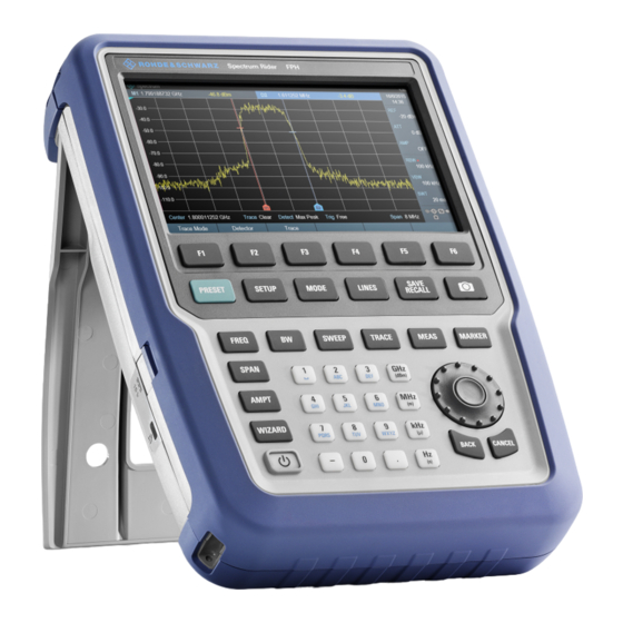
® Instrument Tour R&S Spectrum Rider FPH Overview Control Instrument Tour This chapter describes the front panel, including all function keys and connectors. It also contains general system configuration on the R&S Spectrum Rider as well as the connectivity of the instrument to PC. -
Page 73: Connectors Of The R&S Spectrum Rider
® Instrument Tour R&S Spectrum Rider FPH Connectors of the R&S Spectrum Rider Touch-sensitive screen area Softkey labels (on display) Softkey System Keys DC port (behind protective cap) 10 = Kensington lock 11 = Function Keys 12 = Power key... -
Page 74: Rf Input
® Instrument Tour R&S Spectrum Rider FPH Connectors of the R&S Spectrum Rider 3.2.1 RF Input The RF input 50Ω is located on the top of the R&S Spectrum Rider. Connect a cable or DUT to the RF input with an N connector. Use a cable to con- nect the DUT to the R&S Spectrum Rider, if necessary. -
Page 75: Bnc Connector
® Instrument Tour R&S Spectrum Rider FPH Connectors of the R&S Spectrum Rider Risk of damage of the R&S Spectrum Rider To avoid damage to the coupling capacitor, input attenuator or the mixer, the DC input voltage must never exceed the value specified in the data sheet. -
Page 76: Headphone Jack
® Instrument Tour R&S Spectrum Rider FPH Connectors of the R&S Spectrum Rider 3.2.3 Headphone Jack The 3.5 mm connector for headphones is located on the top of the R&S Spectrum Rider. The internal impedance of the connector is approximately 10 Ω. -
Page 77: Mechanical Locking Device
® Instrument Tour R&S Spectrum Rider FPH Connectors of the R&S Spectrum Rider The R&S Spectrum Rider is supplied with power by the AC/DC transformer power supply via the DC connector. You can also use the DC connector to charge the battery. -
Page 78: Sd Card Slot
® Instrument Tour R&S Spectrum Rider FPH Connectors of the R&S Spectrum Rider You can connect the R&S Spectrum Rider to a PC via USB or LAN and transfer data in both directions. Configure the USB and LAN connection via the "Instrument Setup" menu. For more information, see Chapter 3.7.1, "Configuring the... -
Page 79: Touchscreen Display
® Instrument Tour R&S Spectrum Rider FPH Touchscreen Display Touchscreen Display All measurement results are displayed on the screen. Additionally, the screen dis- play provides status and setting information and you can change the parameters setting with touchscreen gesture. The touch-sensitive screen offers an alternative means of user interaction for quick and easy handling of the instrument. - Page 80 ® Instrument Tour R&S Spectrum Rider FPH Touchscreen Display Figure 3-2: R&S Spectrum Rider touchscreen element The touchscreen display can be divided into several sections: Title Bar Measurement Result View Measurement Trace Window Parameter View A touchscreen is a screen that is touch-sensitive, i.e. it reacts in a specified way when a particular element on the screen is tapped by a finger.
-
Page 81: Title Bar
® Instrument Tour R&S Spectrum Rider FPH Touchscreen Display Touchscreen gesture Special touchscreen features are provided to enhance user experience in using the instrument: ● Swipe horizontally in the trace window, the gesture is used to change the center frequency. -
Page 82: Measurement Result View
® Instrument Tour R&S Spectrum Rider FPH Touchscreen Display 3.3.2 Measurement Result View Special touchscreen gesture You can swipe vertically up or down in the "Measurement result view" to hide or unhide the measurement result view display. For more information, see the "Touchscreen Gesture Element" in the R&S Spectrum Rider user manual The "Measurement result view"... -
Page 83: Measurement Trace Window
® Instrument Tour R&S Spectrum Rider FPH Touchscreen Display Table 3-1: Highlighted marker Highlighted marker in the "Measurement Highlighted marker in the "Measurement result view" trace window" Note: There is a blue frame on the highlighted "M1" marker. For more information on marker measurement, see "Using markers"... -
Page 84: Parameter View
® Instrument Tour R&S Spectrum Rider FPH Touchscreen Display 3.3.4 Parameter View The "Parameter view" contains the important trace setting parameters for the spectrum measurement. It is located at the right side and bottom section of the layout . See Figure 3-2. -
Page 85: Configuration Overview
® Instrument Tour R&S Spectrum Rider FPH Touchscreen Display "ATT" Select "ATT" to display an entry box to config- ure the attenuation setting for the spectrum measurement. "PA" Select "PA" to toggle between the "ON" and "OFF" status for the optional preamplifier (R&S FPH-B22) of the spectrum measurement. - Page 86 ® Instrument Tour R&S Spectrum Rider FPH Touchscreen Display The "Config Overview" window is divided into six categories: Table 3-2: Corresponding dialog box of "Config Overview" window "Config Overview" block Corresponding dialog box Description Select "Input" to configure RF impedance.
- Page 87 ® Instrument Tour R&S Spectrum Rider FPH Touchscreen Display Select "Frequency" to config- ure the center frequency, fre- quency offset and span of the spectrum measurement. Select "Bandwidth" to config- ure resolution bandwidth, video bandwidth and sweep time for the spectrum mea- surement.
-
Page 88: On-Screen Keyboard
® Instrument Tour R&S Spectrum Rider FPH Front Panel Keys On-screen Keyboard The on-screen keyboard is an additional means of interacting with the instrument. It provides convenience of usage with the touchscreen input. Accessing the on-screen keyboard is only available for text-based entry, e.g. save or open a filename. -
Page 89: Screenshot Key
® Instrument Tour R&S Spectrum Rider FPH Front Panel Keys 3.5.2 Screenshot Key The screenshot key provides a quick way to capture screenshot of the current screen at anytime. For more information, see the R&S Spectrum Rider user manual. 3.5.3 Softkey The six softkeys on the front panel are used to access the softkey label. -
Page 90: Function Keys
® Instrument Tour R&S Spectrum Rider FPH Front Panel Keys SYSTEM keys Descriptions MODE Provides the selection between applications. ● Spectrum ● Receiver ● Power Meter ● Maps LINES Configures limit lines. SAVE RECALL Provides a file manager function to facilitate the saving and recalling of result and instrument settings. -
Page 91: Keypad
® Instrument Tour R&S Spectrum Rider FPH Front Panel Keys FUNCTION keys Descriptions SWEEP Sets the sweep time. Sets the trigger mode, trigger threshold and the trigger delay of the external trigger signal. Selects continuous measurement or single measurement. TRACE Configures the measured data acquisition and the analy- sis of the measurement data. -
Page 92: Navigation Controls
® Instrument Tour R&S Spectrum Rider FPH Front Panel Keys It contains the following keys: Type of key Description Alphanumeric Enter numbers and (special) characters in edit dialog boxes. keys Decimal point Inserts a decimal point "." at the cursor position. -
Page 93: Managing Options
® Instrument Tour R&S Spectrum Rider FPH Managing Options The rotary knob has several functions: ● Increments (clockwise direction) or decrements (counter-clockwise direction) the instrument parameters at a defined step width in the case of a numeric entry ● Shifts markers and limit lines on the screen ●... -
Page 94: Checking Options
® Instrument Tour R&S Spectrum Rider FPH Managing Options 4. Enter in the appropriate option key. 5. Confirm the entry with the rotary knob. If you have entered the correct code, the instrument displays a message: "installation successful". If you have entered an incorrect code, the instrument displays a message: "invalid key code!". - Page 95 ® Instrument Tour R&S Spectrum Rider FPH Managing Options The browser will access the R&S License Manager. In this part of the R&S License Manager, you can install and activate licenses on the R&S Spectrum Rider. This page features three areas: ●...
-
Page 96: Configuring The R&S Spectrum Rider
® Instrument Tour R&S Spectrum Rider FPH Configuring the R&S Spectrum Rider The browser will access another part of the R&S License Manager. In this part of the license manager, you can manage licenses already installed on your R&S Spectrum Rider. -
Page 97: Configuring The Hardware
® Instrument Tour R&S Spectrum Rider FPH Configuring the R&S Spectrum Rider 1. Press SETUP key. 2. Select the "Instrument Setup" softkey. A corresponding dialog box to configure the instrument opens. 3. Select the item you want to modify. ●... -
Page 98: Configuring Antennas
® Instrument Tour R&S Spectrum Rider FPH Configuring the R&S Spectrum Rider Configuring the BNC connector You can use the BNC connectors for various applications. For more information on the supported applications, see Chapter 3.2.2, "BNC Connector", on page 26. - Page 99 ® Instrument Tour R&S Spectrum Rider FPH Configuring the R&S Spectrum Rider Enabling the antenna 1. In the "Instrument Setup" dialog box, select the "Antenna" menu item. A drop-down menu to select the antenna opens. 2. Select the "HL300", "HE300" or "HE400" "Antenna" menu item.
- Page 100 ® Instrument Tour R&S Spectrum Rider FPH Configuring the R&S Spectrum Rider 2. Select "On" to enable the compass. The R&S Spectrum Rider shows the magnetic declination of your current posi- tion in the "Magnetic Declination" menu item. Showing compass information 1.
- Page 101 ® Instrument Tour R&S Spectrum Rider FPH Configuring the R&S Spectrum Rider b) "Save current GPS position" Using the toggle switch tags your current position in the map material. 2. Select the required function. Calibrating the antenna If you need to know technical specification about the antenna, for example for service or support, you can get the necessary information from the "Antenna Service Menu"...
- Page 102 ® Instrument Tour R&S Spectrum Rider FPH Configuring the R&S Spectrum Rider The R&S Spectrum Rider starts the calibration. For antenna calibration, it is necessary to move the antenna according to the direction as instructed on the screen. 4. When calibration completes, the R&S Spectrum Rider displays a "Calibration Successful"...
-
Page 103: Using The Gps Receiver
® Instrument Tour R&S Spectrum Rider FPH Configuring the R&S Spectrum Rider The R&S Spectrum Rider displays the calibration result. 3.7.3 Using the GPS Receiver The R&S Spectrum Rider can locate your exact position if you connect the GPS receiver (R&S HA-Z340, order number 1321.1392.02) to the USB connector. - Page 104 ® Instrument Tour R&S Spectrum Rider FPH Configuring the R&S Spectrum Rider Location to secure GPS receiver (R&S HA-Z340) Figure 3-3: Location of GPS receiver ● Tighten the knob screw supplied with the GPS receiver to the screw track at the back of R&S Spectrum Rider.
- Page 105 ® Instrument Tour R&S Spectrum Rider FPH Configuring the R&S Spectrum Rider When "GPS" item is turned on, the R&S Spectrum Rider is ready to receive GPS data. Displaying GPS information 1. In the "Instrument Setup" dialog box, select the "Show GPS Information" item.
-
Page 106: Configuring Date And Time
® Instrument Tour R&S Spectrum Rider FPH Configuring the R&S Spectrum Rider 2. Select the desired format from the drop-down menu. 3.7.4 Configuring Date and Time The R&S Spectrum Rider has an internal clock that can apply a date and time- stamp. -
Page 107: Selecting Regional Settings
® Instrument Tour R&S Spectrum Rider FPH Configuring the R&S Spectrum Rider Selecting the time zone 1. In the "Instrument Setup" dialog box, select the "Time Zone" item. 2. Enter a positive or negative time offset relative to the system time with the numeric keys. -
Page 108: Configuring The Display
® Instrument Tour R&S Spectrum Rider FPH Configuring the R&S Spectrum Rider 2. Select one of the languages from the drop-down menu. 3. Reboot the device to activate the choice of selected language. Setting the date format The R&S Spectrum Rider provides two different formats to display the date. - Page 109 ® Instrument Tour R&S Spectrum Rider FPH Configuring the R&S Spectrum Rider The display of the R&S Spectrum Rider is a TFT color LCD display. The ideal brightness of the display depends on the intensity of the backlight. To strike a balance between battery operating time and screen display quality, set the backlight intensity to the minimum brightness needed.
- Page 110 ® Instrument Tour R&S Spectrum Rider FPH Configuring the R&S Spectrum Rider 2. Select the desire color scheme from the drop-down menu. a) "Color" selects a color display. b) "Black & White" selects monochrome display. c) "Printer Friendly" inverts the colors.
-
Page 111: Configuring The Audio Output
® Instrument Tour R&S Spectrum Rider FPH Configuring the R&S Spectrum Rider 3. Select "OFF" to deactivate the touchscreen interface. Note: If the touch interface is not activated, the On-screen keyboard is dis- abled. 3.7.7 Configuring the Audio Output The audio settings control the audio output of the system. -
Page 112: Configuring Power Supply
® Instrument Tour R&S Spectrum Rider FPH Configuring the R&S Spectrum Rider 2. Enter the volume you want with the numeric keys. The system beeper volume is a percentage from 0% to 100% with 100% being the loudest. 3. Confirm the entry with the rotary knob. -
Page 113: Resetting The R&S Spectrum Rider
® Instrument Tour R&S Spectrum Rider FPH Configuring the R&S Spectrum Rider Setting the battery low level The battery low level is a reminder that the remaining battery charge might be used up soon. When the battery low level is reached, the battery symbol in the... - Page 114 ® Instrument Tour R&S Spectrum Rider FPH Configuring the R&S Spectrum Rider Presetting the R&S Spectrum Rider The PRESET key resets the R&S Spectrum Rider to the default setup of the cur- rently active operating mode. This default setup allows you to define the instrument with a new configuration based on a defined measurement parameter without using parameters from a previous measurement unintentionally still being active.
-
Page 115: Connecting The R&S Spectrum Rider To A Pc
® Instrument Tour R&S Spectrum Rider FPH Connecting the R&S Spectrum Rider to a PC ● Select "Yes" to perform the reset. During the reboot, it shows a corre- sponding message. ● Select "No" to cancel the reset. Connecting the R&S Spectrum Rider to a PC The R&S Spectrum Rider comes with the R&S InstrumentView software package. -
Page 116: Lan Connection
® Instrument Tour R&S Spectrum Rider FPH Connecting the R&S Spectrum Rider to a PC 3.8.1 LAN Connection You can connect the R&S Spectrum Rider directly to the PC with a LAN cable. LAN port is located behind a protective cap on the right side of the R&S Spectrum Rider. - Page 117 ® Instrument Tour R&S Spectrum Rider FPH Connecting the R&S Spectrum Rider to a PC 2. In the "Instrument Settings" dialog box, select the "Subnet Mask" item. 3. Enter the subnet mask of the PC with the numeric keys. After you have matched the subnet mask, you can define the IP address.
- Page 118 ® Instrument Tour R&S Spectrum Rider FPH Connecting the R&S Spectrum Rider to a PC 3. Confirm the entry with the rotary knob. 4. Enter the IP address of the PC with the numeric keys. Configuring the R&S InstrumentView software package 1.
- Page 119 ® Instrument Tour R&S Spectrum Rider FPH Connecting the R&S Spectrum Rider to a PC 4. Specify a name for the new network connection, e.g. R&S Spectrum Rider. 5. Enter the IP address for the R&S Spectrum Rider (in this case 192.168.1.20).
-
Page 120: Usb Connection
® Instrument Tour R&S Spectrum Rider FPH Connecting the R&S Spectrum Rider to a PC DHCP is off by default. Turn it on like this: 1. In the "Instrument Setup" dialog box, select the "DHCP" item. 2. Select "DHCP" to "On" to activate DHCP. - Page 121 ® Instrument Tour R&S Spectrum Rider FPH Connecting the R&S Spectrum Rider to a PC 4. Select the "Scan" button to identify the R&S Spectrum Rider. 5. Confirm the selection with the "Connect" button. Getting Started 1321.0996.02 ─ 05.00...
-
Page 122: Trying Out The Instrument
® Trying Out the Instrument R&S Spectrum Rider FPH Using the Spectrum Analyzer Trying Out the Instrument This chapter provides a short overview of the first steps of the measurements you can perform with the R&S Spectrum Rider. ● Using the Spectrum Analyzer................73... -
Page 123: Using The Preamplifier
® Trying Out the Instrument R&S Spectrum Rider FPH Using the Spectrum Analyzer You can also set the attenuation manually. TheR&S Spectrum Rider provides attenuation in the range from 0 dB to 40 dB in 5 dB steps. 4. Press the AMPT key. -
Page 124: Measuring Cw Signals
® Trying Out the Instrument R&S Spectrum Rider FPH Using the Spectrum Analyzer gain of the amplifier is in the range from 15 dB to 20 dB and increases the sensi- tivity by 10 dB to 15 dB. In the signal path, the preamplifier comes after the input protection circuit and before the RF attenuator of the R&S Spectrum Rider to provide excellent sensitiv-... - Page 125 ® Trying Out the Instrument R&S Spectrum Rider FPH Using the Spectrum Analyzer Test setup Connect the RF output of the signal generator to the RF input of the R&S Spec- trum Rider. Signal generator settings: ● Frequency: 500 MHz ●...
- Page 126 ® Trying Out the Instrument R&S Spectrum Rider FPH Using the Spectrum Analyzer Setting the reference level The level at the top of the measurement diagram is called the reference level. To obtain the best dynamic range from the R&S Spectrum Rider, you should use its full level range.
- Page 127 ® Trying Out the Instrument R&S Spectrum Rider FPH Using the Spectrum Analyzer ► Press the MARKER key. The R&S Spectrum Rider activates a marker and puts it on the maximum value on the trace. The coordinates of the marker are shown in a table above the measurement diagram.
-
Page 128: Measuring Harmonics
® Trying Out the Instrument R&S Spectrum Rider FPH Using the Spectrum Analyzer The measurement result of the frequency counter is displayed at the "Measure- ment result view". When the frequency counter is active, the resolution of the fre- quency readout is always 0.1 Hz, regardless of the span. The accuracy is deter- mined by the internal reference frequency which is far more exact than the pixel- oriented marker readout. - Page 129 ® Trying Out the Instrument R&S Spectrum Rider FPH Using the Spectrum Analyzer Detecting harmonics 1. Press the PRESET key. The R&S Spectrum Rider is reset to its default state. After the preset, the R&S Spectrum Rider displays the frequency spectrum over its full frequency span.
-
Page 130: Using A Power Sensor
® Trying Out the Instrument R&S Spectrum Rider FPH Using a Power Sensor To measure the harmonic ratio, set the marker on the signal and a delta marker on the second harmonic. 9. Press the MARKER key. The R&S Spectrum Rider sets a marker on the trace maximum. The trace maximum corresponds to the signal. -
Page 131: Measuring The Power With A Power Sensor
® Trying Out the Instrument R&S Spectrum Rider FPH Using a Power Sensor For highly accurate power measurements, you can connect one of the power sen- sors that are supported by the R&S Spectrum Rider. For a list of R&S Spectrum Rider supported power sensor, refer to "Power Meter"... - Page 132 ® Trying Out the Instrument R&S Spectrum Rider FPH Using a Power Sensor 1 = Supported power sensor (e.g R&S FSH-Z1, R&S NRP-Z11) 2 = Power sensor connector (DUT) 3 = USB binder adaptor (R&S FSH-Z101) 4 = USB port connector Measuring the power 1.
- Page 133 ® Trying Out the Instrument R&S Spectrum Rider FPH Using a Power Sensor A popup message box is displayed to provide instructions during the zeroing of the power sensor. 2. Disconnect the power sensor from any signal sources. 3. Select the "Continue" softkey to start zeroing.
-
Page 134: Measuring Power And Return Loss
® Trying Out the Instrument R&S Spectrum Rider FPH Using a Power Sensor Set the frequency To get the best results, enter the frequency of the signal under test. 1. Select the "Freq" softkey. The R&S Spectrum Rider opens an entry box to enter the frequency. - Page 135 ® Trying Out the Instrument R&S Spectrum Rider FPH Using a Power Sensor The ratio between the forward and reverse power is a measure of the load match- ing. The R&S Spectrum Rider displays it as the return loss or standing wave ratio.
- Page 136 ® Trying Out the Instrument R&S Spectrum Rider FPH Using a Power Sensor 1 = Directional power sensor R&S FSH-Z14 or Z44 2 = Source 3 = Load 4 = USB binder adaptor (R&S FSH-Z144) 5 = USB port connector Measuring the power 1.
-
Page 137: Saving And Recalling Results And Settings
® Trying Out the Instrument R&S Spectrum Rider FPH Saving and Recalling Results and Settings To get the best results, you should also define the frequency of the signal. For more information on the measuring power and return loss, see "Power Meter" in the R&S Spectrum Rider user manual. - Page 138 ® Trying Out the Instrument R&S Spectrum Rider FPH Saving and Recalling Results and Settings The R&S Spectrum Rider provides two USB ports and one micro-SD card slot. For more information on saving measurement results and settings, see "Saving Datasets" in the R&S Spectrum Rider user manual.
- Page 139 ® Trying Out the Instrument R&S Spectrum Rider FPH Saving and Recalling Results and Settings Getting Started 1321.0996.02 ─ 05.00...
-
Page 140: Index
® Index R&S Spectrum Rider FPH Index AC adapter ..........15 Frequency ..........75 Accessory detection ........ 48 Front panel keys ........39 Antenna Function keys .......... 41 Configuring ......... 48 Application cards ........8 Application notes ........8 Getting started ........... 7 Attenuation .......... - Page 141 ® Index R&S Spectrum Rider FPH Power overload beep ......63 Power sensor White papers ..........8 Zeroing ..........81 Power sensor port ........27 Power settings ......... 63 Preamplifier ..........74 Preset ............64 Putting into operation ......11 Reference level ........75 Regional settings ........
Need help?
Do you have a question about the Spectrum Rider FPH and is the answer not in the manual?
Questions and answers