
Related Manuals for Rohde & Schwarz R&S FPL1-K30


Summary of Contents for Rohde & Schwarz R&S FPL1-K30
- Page 1 ® R&S FPL1-K30 Noise Figure Measurements User Manual (;ÜR52) 1178340502 Version 10...
- Page 2 ® This manual applies to the following R&S FPL1000 models with firmware version 2.20 and later: ● ® R&S FPL1003 (1304.0004K03) - FPL1000 with maximum frequency 3 GHz ● ® R&S FPL1007 (1304.0004K07) - FPL1000 with maximum frequency 7.5 GHz ●...
-
Page 3: Table Of Contents
® Contents R&S FPL1-K30 Contents 1 Preface....................7 Documentation overview....................7 1.1.1 Getting started manual....................7 1.1.2 User manuals and help....................7 1.1.3 Service manual....................... 7 1.1.4 Instrument security procedures..................8 1.1.5 Printed safety instructions....................8 1.1.6 Specifications and brochures..................8 1.1.7 Release notes and open source acknowledgment (OSA)..........8 1.1.8 Application notes, application cards, white papers, etc...........8 1.1.9... - Page 4 ® Contents R&S FPL1-K30 Calibration (2nd stage correction)................34 Using smart noise sources..................37 Separating signals by selecting an appropriate resolution bandwidth....38 Analyzing several traces - trace mode..............39 Using markers......................40 5 Configuration..................42 Configuration overview....................42 Defining the measurement frequency...............44 5.2.1 Defining a frequency set....................
- Page 5 ® Contents R&S FPL1-K30 Using markers......................86 6.4.1 Marker configuration..................... 86 6.4.2 Marker positioning......................89 7 Remote control commands for noise figure measurements... 92 Common suffixes......................93 Introduction......................... 93 7.2.1 Conventions used in descriptions................. 93 7.2.2 Long and short form...................... 94 7.2.3 Numeric suffixes......................94 7.2.4...
- Page 6 ® Contents R&S FPL1-K30 7.18 Working with limit lines.................... 163 7.18.1 Defining general characteristics of a limit line............. 164 7.18.2 Defining horizontal data points..................165 7.18.3 Controlling lower limit lines..................166 7.18.4 Controlling upper limit lines..................167 7.18.5 Managing limit lines.....................169 7.18.6 Controlling limit checks....................
-
Page 7: Preface
® Preface R&S FPL1-K30 Documentation overview 1 Preface This chapter provides safety-related information, an overview of the user documenta- tion and the conventions used in the documentation. 1.1 Documentation overview This section provides an overview of the R&S FPL1000 user documentation. Unless specified otherwise, you find the documents at: www.rohde-schwarz.com/manual/FPL1000 1.1.1 Getting started manual... -
Page 8: Instrument Security Procedures
® Preface R&S FPL1-K30 Documentation overview The service manual is available for registered users on the global Rohde & Schwarz information system (GLORIS): https://gloris.rohde-schwarz.com 1.1.4 Instrument security procedures Deals with security issues when working with the R&S FPL1000 in secure areas. It is available for download on the internet. -
Page 9: Video Tutorials
® Preface R&S FPL1-K30 Conventions used in the documentation 1.1.9 Video tutorials Video tutorials that show you how to get started and perform basic tasks with the R&S FPL1000 are available on the Rohde & Schwarz internet site: https://www.rohde-schwarz.com/manual/r-s-fpl1000-trying-out-basic-measurement- tasks-manuals_78701-567115.html Find various videos on Rohde &... -
Page 10: Notes On Screenshots
® Preface R&S FPL1-K30 Conventions used in the documentation The term "select" may refer to any of the described methods, i.e. using a finger on the touchscreen, a mouse pointer in the display, or a key on the instrument or on a key- board. -
Page 11: Welcome To The Noise Figure Measurement Application
® Welcome to the noise figure measurement application R&S FPL1-K30 Starting the noise application 2 Welcome to the noise figure measurement application The R&S FPL1-K30 is a firmware application that adds functionality to perform "noise figure" measurements to the R&S FPL1000. Noise Source Control The Noise Source Control connector on the R&S FPL1000 is a prerequisite for the R&S FPL1 Noise Figure measurements application. -
Page 12: Understanding The Display Information
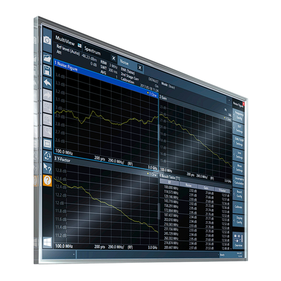
® Welcome to the noise figure measurement application R&S FPL1-K30 Understanding the display information All settings specific to "noise figure" measurements are in their default state. Multiple Channel setups and Sequencer Function When you activate an application, a new channel setup is created which determines the measurement settings for that application ("Channel"). - Page 13 ® Welcome to the noise figure measurement application R&S FPL1-K30 Understanding the display information Figure 2-1: Screen layout of the noise figure measurement application 1 = Toolbar 2 = Channel setup bar 3 = Diagram header 4 = Result display 5 = Softkey bar 6 = Status bar Channel setup bar information...
- Page 14 ® Welcome to the noise figure measurement application R&S FPL1-K30 Understanding the display information Figure 2-2: Window title bar information for the R&S FPL1 Noise Figure measurements application 1 = Window number 2 = Window type 3 = Trace color and number 4 = Trace mode Status bar information Global instrument settings, the instrument status and any irregularities are indicated in...
-
Page 15: Measurements And Result Displays
® Measurements and result displays R&S FPL1-K30 3 Measurements and result displays The R&S FPL1-K30 measures the "Noise Figure" of a DUT and displays the results graphically and numerically. Each graphical result display shows the "Noise Figure" from a different perspective. In the default configuration, the application shows the "Noise Figure"... -
Page 16: Noise Figure
® Measurements and result displays R&S FPL1-K30 Single frequency measurements In all graphical result displays, the horizontal axis represents a chronological order of measurement results for the frequency you are testing. The axis has no unit, but is made up out of several index values that represent time. Each index value represents one measurement point and therefore one measurement on the single frequency you are analyzing. -
Page 17: Gain
® Measurements and result displays R&S FPL1-K30 Remote command: LAY:ADD:WIND? '2',RIGH,NOIS see on page 102 LAYout:ADD[:WINDow]? Results:TRACe<t>[:DATA]? <Trace>,NOISe Gain Shows the "Gain" characteristics of the DUT. The vertical axis shows the level of the "Gain" in dB. The scale depends on the set- tings in the "Display Configuration"... -
Page 18: Y-Factor
® Measurements and result displays R&S FPL1-K30 Noise Temperatur with Power Bandwidth Boltzmann constant The vertical axis shows the "Temperature" in Kelvin. The scale depends on the settings in the "Display Configuration" dialog box. Remote command: LAY:ADD:WIND? '2',RIGH,TEMP see on page 102 LAYout:ADD[:WINDow]? -
Page 19: Enr Measured
® Measurements and result displays R&S FPL1-K30 Remote command: LAY:ADD:WIND? '2',RIGH,YFAC see on page 102 LAYout:ADD[:WINDow]? Results: TRACe<t>[:DATA]? <Trace>,YFACtor ENR Measured Shows the results of the ENR measurement. To measure the ENR of a noise source, first attach a noise source with known ENR to the device, enter the ENR of this noise source to the calibration ENR table and cali- brate using this one. -
Page 20: Level (Hot)
® Measurements and result displays R&S FPL1-K30 Remote command: LAY:ADD:WIND? '2',RIGH,ENR see on page 102 LAYout:ADD[:WINDow]? Results: TRACe<t>[:DATA]? <Trace>,ENR Level (Hot) Shows the absolute power characteristics at the instrument input. The noise source is turned on. The vertical axis shows the power in dBm. The scale depends on the settings in the "Display Configuration"... -
Page 21: Cal Y-Factor
® Measurements and result displays R&S FPL1-K30 Remote command: LAY:ADD:WIND? '2',RIGH,PCOL see on page 102 LAYout:ADD[:WINDow]? Results: TRACe<t>[:DATA]? <Trace>,PCOLd Cal Y-Factor Shows the ratio of the hot and the cold power measured during calibration. The "Y-factor" indicates the quality of measurement tolerances and uncertainties. To get the result, the application measures the power with the noise source turned on (hot power) and the noise source turned off (cold power), but without the DUT inserted. -
Page 22: Cal Level (Hot)
® Measurements and result displays R&S FPL1-K30 Cal Level (Hot) Shows the absolute power characteristics at the instrument input during the calibration measurement. The noise source is turned on, the DUT is not inserted. The vertical axis shows the power in dBm. The scale depends on the settings in the "Display Configuration"... -
Page 23: P Hot
® Measurements and result displays R&S FPL1-K30 Remote command: LAY:ADD:WIND? '2',RIGH,CPC see on page 102 LAYout:ADD[:WINDow]? Results: TRACe<t>[:DATA]? <Trace>,CPCold P Hot Shows the relative power with a hot noise source in dB. The scale depends on the settings in the "Display Configuration" dialog box. Remote command: LAY:ADD? '1',RIGH,DPH, see on page 102... -
Page 24: Result Table
® Measurements and result displays R&S FPL1-K30 Remote command: LAY:ADD? '1',RIGH,DPC, see on page 102 LAYout:ADD[:WINDow]? Results: TRACe<t>[:DATA]? <Trace>,DPCold Result Table Shows the measurement results in numerical form in a table. The contents of the table depend on the "Display Settings". By default it shows the "Noise Figure", "Gain"... - Page 25 ® Measurements and result displays R&S FPL1-K30 The first four columns of the table are fix. ● Type Shows the marker type. 'M' represents a normal marker, 'D' represents a delta marker. ● Shows the reference marker for relative delta markers. ●...
-
Page 26: Measurement Basics
® Measurement basics R&S FPL1-K30 Tuning modes 4 Measurement basics The measurement basics contain background information on the terminology and prin- ciples of "noise figure" measurements. "Noise figure" measurements determine the noise that a device under test (DUT) adds to a signal as that signal passes through the DUT. ●... -
Page 27: Swept Measurements
® Measurement basics R&S FPL1-K30 Tuning modes The application provides several measurement modes or tuning modes. ● Swept measurements..................... 27 ● Frequency table measurements................27 ● Single frequency measurements................28 4.1.1 Swept measurements The sweep tuning mode performs measurements on a set of discrete frequencies based on the frequency parameters. -
Page 28: Single Frequency Measurements
® Measurement basics R&S FPL1-K30 Measurement modes 4.1.3 Single frequency measurements The single frequency tuning mode performs one or several consecutive measure- ments on a single frequency. You can perform the measurement on any frequency that is supported by the hardware you are using. Single frequency measurements are a way to facilitate manual adjustments for "noise figure"... - Page 29 ® Measurement basics R&S FPL1-K30 Measurement modes Performing a manual measurement In manual measurement mode, you have to measure (or calibrate) the hot and cold power characteristics of the DUT separately. When you start the measurement, the application opens a dialog box that allows you to select the type of measurement to perform next.
-
Page 30: Dut Types
® Measurement basics R&S FPL1-K30 DUT types Clearing results To replace the previous calibration or measurement results, clear the currently stored data using the "Clear Calibration Results" or "Clear Measurement Results" function. Returning to automatic measurement mode When you are in automatic measurement mode and select a noise source with resistor characteristics, the application automatically selects the manual measurement mode. -
Page 31: Image Frequency Rejection
® Measurement basics R&S FPL1-K30 Image frequency rejection If you have selected a frequency-converting DUT measurement mode, the layout of the "Overview" dialog box adds the local oscillator to the test setup. The local oscillator can have a fixed or a variable frequency. If the LO frequency is fixed, the intermediate frequency (IF) resulting from the conversion process is variable (depending on the input signal). - Page 32 ® Measurement basics R&S FPL1-K30 Image frequency rejection Double sideband measurements Double sideband mixers use both sidebands to the same extent. Both RF and image frequency are converted. In that case, turn off image rejection. = frequency of the local oscillator ±...
- Page 33 ® Measurement basics R&S FPL1-K30 Image frequency rejection For mixers whose image rejection is known, define the magnitude of image rejection in dB as accurately as possible. Otherwise, measurement results ("noise figure" and "gain") deviate between 0 dB to 3 dB. If you do not know the image rejection characteristics of a mixer, use a custom test setup including an additional filter.
-
Page 34: Calibration (2Nd Stage Correction)
® Measurement basics R&S FPL1-K30 Calibration (2nd stage correction) measurement is similar to measurements on a mixer with an average sideband sup- pression. 4.5 Calibration (2nd stage correction) The calibration procedure of the application measures the inherent noise of the R&S FPL1000 you are using. - Page 35 ® Measurement basics R&S FPL1-K30 Calibration (2nd stage correction) If you change the frequency, while the frequency span stays the same or is reduced, the application interpolates the correction data for the new measurement points. A new calibration is not required. However, measurements based on interpolated data can result in an increased measurement uncertainty.
- Page 36 ® Measurement basics R&S FPL1-K30 Calibration (2nd stage correction) Figure 4-1: Noise figure calibration setup 1. Connect the noise source directly and without a cable to the RF input of the ana- lyzer. 2. Connect the noise source to the +28 V voltage supply (Noise Source Control con- nector) on the back of the R&S FPL1000.
-
Page 37: Using Smart Noise Sources
® Measurement basics R&S FPL1-K30 Using smart noise sources To achieve a valid calibration by importing a saved one, all parameters of R&S FPL1000-K30 must match exactly to the ones that have been used for the cali- bration. At the import of a calibration, a preview dialog is shown which contains all rele- vant parameters of the calibration to be imported and an indication (green / red) if they match to the current instrument and option settings. -
Page 38: Separating Signals By Selecting An Appropriate Resolution Bandwidth
® Measurement basics R&S FPL1-K30 Separating signals by selecting an appropriate resolution bandwidth not be edited in the R&S FPL1 Noise Figure measurements application. The name of each ENR table contains the serial number of the SNS. For smart noise sources, use the lemosa female connector on the front panel. To con- nect a noise source with a BNC connector, use the noise source control female con- nector on the rear panel (requires the R&S R&S FPL1000-B28V option). -
Page 39: Analyzing Several Traces - Trace Mode
® Measurement basics R&S FPL1-K30 Analyzing several traces - trace mode depending on the current frequency of the sweep point. The variable RBW and sweep times are defined in the frequency table (see Chapter 5.2.3, "Using a frequency table", on page 48). The defined RBW and sweep times are also included in a table export. In the channel bar, the bandwidth and sweep time range of the variable values is indi- cated. -
Page 40: Using Markers
® Measurement basics R&S FPL1-K30 Using markers 4.9 Using markers Markers are used to mark points on traces, to read out the results of a particular mea- surement point or compare results of different traces. The noise application provides four markers. When you activate a marker, the application automatically positions it on the first mea- surement point (left border of the diagram) of trace 1, regardless of how many traces are active. - Page 41 ® Measurement basics R&S FPL1-K30 Using markers "View" trace mode, e.g. to compare measurement results. Note that at least one active marker has to be a normal marker. The application shows the results at the marker position directly in the diagram area (up to two markers) or in the marker table (if you use more than two markers).
-
Page 42: Configuration
® Configuration R&S FPL1-K30 Configuration overview 5 Configuration "Noise figure" measurements require a special application on the R&S FPL1000, which you activate using [MODE]. The Noise Source Control connector on the R&S FPL1000 is also a prerequisite for the R&S FPL1 Noise Figure measurements application. Without this connector, no mea- surement can be performed. - Page 43 ® Configuration R&S FPL1-K30 Configuration overview In addition to the main measurement settings, the "Overview" provides quick access to the main settings dialog boxes. The individual configuration steps are displayed in the order of the data flow. Thus, you can easily configure an entire measurement channel from input over processing to output and analysis by stepping through the dialog boxes as indicated in the "Overview".
-
Page 44: Defining The Measurement Frequency
® Configuration R&S FPL1-K30 Defining the measurement frequency Chapter 6.1, "Configuring the display", on page 78 To configure settings ► Select any button in the "Overview" to open the corresponding dialog box. Select a setting in the channel bar (at the top of the measurement channel tab) to change a specific setting. - Page 45 ® Configuration R&S FPL1-K30 Defining the measurement frequency Tuning Mode......................... 45 Center........................... 46 Span..........................46 Start and Stop Frequency..................... 46 (Measurement) Points....................46 Step..........................47 Tuning Mode Selects the tuning or measurement mode. For more information, see Chapter 4.1, "Tuning modes", on page 26. Tuning mode selection is also available via softkeys ("Sweep Mode", "Frequency Table Mode", "Single Frequency Mode") in the "Sweep"...
- Page 46 ® Configuration R&S FPL1-K30 Defining the measurement frequency on page 112 [SENSe:]CONFigure:FREQuency:SINGle on page 150 INITiate<n>[:IMMediate] Center Defines the center of the measurement frequency range. If you change the center frequency, the application changes the start and stop fre- quency according to the span you have set. The "Center"...
-
Page 47: Configuring Single Frequency Measurements
® Configuration R&S FPL1-K30 Defining the measurement frequency Step Defines the frequency step size in the frequency table. The stepsize corresponds to the distance between two consecutive measurement points. If you change the stepsize, the application changes the measurement point according to the span. -
Page 48: Using A Frequency Table
® Configuration R&S FPL1-K30 Defining the measurement frequency Coupled to Sweep List Couples or decouples frequency selection to the contents of a sweep list. If you couple the frequency to the sweep list, the application allows you to select only the frequencies currently part of the frequency list. - Page 49 ® Configuration R&S FPL1-K30 Defining the measurement frequency Frequency Table......................49 Clear Table........................50 Populate Table......................50 Insert..........................50 Delete..........................50 Import / Export.......................50 Frequency Table Shows the current measurement points. The table is made up of one column that represents the measurement frequency. Each frequency corresponds to one measurement point.
- Page 50 ® Configuration R&S FPL1-K30 Defining the measurement frequency Select Populate Table to predefine the RBW and sweep times to be used. For each sweep point with a frequency under 10 MHz in the table, suitable settings are defined. For higher frequencies, the values provided in the measurement settings are used (indicated by "--"...
-
Page 51: Selecting Dut Characteristics
® Configuration R&S FPL1-K30 Selecting DUT characteristics 5.3 Selecting DUT characteristics Access: "Overview" > "DUT" > "DUT Settings" The "DUT" button opens a dialog box to configure the characteristics of the DUT you are testing. The dialog box contains a schematic overview of the DUT input and output characteristics and the way it is integrated into the test setup. -
Page 52: Configuring The Noise Source
® Configuration R&S FPL1-K30 Configuring the noise source Image Rejection Turns image rejection of the DUT on and off. If you set an image rejection of 0 dB, the image frequency passes completely. If you set a high image rejection (up to 999.99 dB), the image frequency is suppressed com- pletely. - Page 53 ® Configuration R&S FPL1-K30 Configuring the noise source Auto Select SNS......................53 Noise Source.........................54 Measurement........................ 54 Common Noise Source....................55 Calibration........................55 Temperature........................56 Auto Select SNS If enabled (default), the R&S FPL1 Noise Figure measurements application automati- cally recognizes a connected smart noise source and uses it for the noise measure- ment.
- Page 54 ® Configuration R&S FPL1-K30 Configuring the noise source If no SNS is connected, a red "No SNS connected" warning is displayed: If "Auto Select SNS" is disabled, you must manually change the noise source to SNS and select the required tables, if necessary (see "Frequency Table"...
- Page 55 ® Configuration R&S FPL1-K30 Configuring the noise source If the noise characteristics are based on a table, the ENR level and temperatures typi- cally depend on the measurement frequency. You can select an existing table from the dropdown menu next to the radio button, if it is active. For more information on ENR and temperature tables, see Chapter 5.4.2, "Using an ENR or temperature table",...
-
Page 56: Using An Enr Or Temperature Table
® Configuration R&S FPL1-K30 Configuring the noise source Remote command: mode:[SENSe:]CORRection:ENR:CALibration:MODE on page 119 Constant ENR: on page 119 [SENSe:]CORRection:ENR:CALibration:SPOT Select table: [SENSe:]CORRection:ENR:CALibration:TABLe:SELect on page 120 Constant temperature: [SENSe:]CORRection:ENR:CALibration:SPOT:COLD on page 118 Constant temperature: [SENSe:]CORRection:ENR:CALibration:SPOT:HOT on page 118 Temperature Defines the absolute room temperature in degree Celsius or Fahrenheit. The room temperature is required for the calculation of the real ENR of the noise source, because an ENR table is based on a temperature of 290K. - Page 57 ® Configuration R&S FPL1-K30 Configuring the noise source ENR or temperature tables contain the noise source characteristics for particular fre- quencies. If the table does not contain ENR or temperature values for one of the mea- surement frequencies, the application interpolates between the values. The "Table Settings"...
- Page 58 ® Configuration R&S FPL1-K30 Configuring the noise source For a smart noise source, the table contains the provided ENR and uncertainty table. The table for the connected noise source is automatically recognized and highlighted. The name of the ENR table contains the serial number of the SNS. The "default" table also contains the data for the most recently connected smart noise source.
- Page 59 ® Configuration R&S FPL1-K30 Configuring the noise source Copy To Opens the Edit Table dialog box to modify the selected table and save it under a new name. Import / Export Table Opens a dialog box to select a table to import or export. Smart noise source tables can be exported, but not re-imported.
-
Page 60: Temperature[:Data]
® Configuration R&S FPL1-K30 Configuring additional loss "Value" ENR value or loss in dB. For a resistor, the characteristics of the resistor are defined by the noise temperatures T and T instead of a single value. The unit in cold that case is Kelvin (degrees). - Page 61 ® Configuration R&S FPL1-K30 Configuring additional loss You can define the loss characteristics of the signal path to the DUT input and the sig- nal path from the DUT output to the analyzer. Furthermore, you can define the loss characteristics of the signal path from the noise source directly to the analyzer for the calibration measurement.
- Page 62 ® Configuration R&S FPL1-K30 Configuring additional loss If the loss is based on a table, the loss values are interpolated to the measurement fre- quencies. You can select a table from the dropdown menu next to the radio button, if it is active.
-
Page 63: Using A Loss Table
® Configuration R&S FPL1-K30 Configuring additional loss If the loss is constant, the same loss is used for all frequencies in the frequency table. If you have selected a constant loss, you can also define its value in the input field next to the radio button. - Page 64 ® Configuration R&S FPL1-K30 Configuring additional loss each frequency that is measured. If the table does not contain a loss for one of the measurement frequencies, the application interpolates between values. The "Table Settings" tab contains a list of loss tables currently available on the R&S FPL1000.
-
Page 65: Configuring The Analyzer
® Configuration R&S FPL1-K30 Configuring the analyzer Import / Export Table Opens a dialog box to select a loss table to import or export. An import copies the loss table into the default loss table directory. The file extension can be *.loss or *.s2p. In case the file extension is *.s2p, the S21 vector is parsed out of the *.s2p file. - Page 66 ® Configuration R&S FPL1-K30 Configuring the analyzer Auto Level Range......................68 Attenuation......................68 Preamplifier........................68 2nd Stage Correction Turns 2nd stage correction on and off. If enabled, the application uses the calibration data to compensate for the inherent noise of the analyzer when calculating the measurement results. If disabled, the application does not correct the measurement results, even if a valid calibration has been performed.
- Page 67 ® Configuration R&S FPL1-K30 Configuring the analyzer "Variable" Uses a variable sweep time, depending on the current frequency of the sweep point, as defined in the frequency table (see Chapter 5.2.3, "Using a frequency table", on page 48); In the channel bar, the bandwidth and sweep time range of the vari- able values is indicated.
-
Page 68: Input:attenuation
® Configuration R&S FPL1-K30 Configuring the analyzer The application determines the reference level before the calibration starts. The reference level is based on several test measurements on the start frequency. For more information, see "Auto Level Range" on page 68. ●... -
Page 69: Using The Uncertainty Calculator
® Configuration R&S FPL1-K30 Using the uncertainty calculator The input signal is amplified by 20 dB if the preamplifier option is activated. Remote command: on page 137 INPut:GAIN:STATe 5.7 Using the uncertainty calculator Access: [MEAS CONFIG] > "Uncertainty Calculation" "Noise figure" measurements are subject to uncertainty. The "noise figure" measure- ment is meaningless if the measurement uncertainty is too large. -
Page 70: Configuring Noise Source Characteristics
® Configuration R&S FPL1-K30 Using the uncertainty calculator Uncertainty values and systematic error recognition Note that the uncertainty calculation only takes systematic measurement inaccuracies into account. The most significant inaccuracies are: ● Uncertainties of the noise source and the analyzer ●... - Page 71 ® Configuration R&S FPL1-K30 Using the uncertainty calculator If you are using a different noise source during calibration and measurement, the Uncertainty Calculator adds an Output Match ENR Uncert(ainty) required for uncertainty calculation during calibration. Note that you have to turn off the Common Noise Source if you have to define the val- ues of the noise source used during calibration.
-
Page 72: Configuring Dut Characteristics
® Configuration R&S FPL1-K30 Using the uncertainty calculator If a smart noise source is used, the ENR uncertainty values defined in the SNS table are used. Remote command: on page 142 CALCulate<n>:UNCertainty:ENR:UNCertainty on page 141 CALCulate<n>:UNCertainty:ENR:CALibration:UNCertainty Temperature Uncert(ainty) Defines the uncertainty of the hot and cold temperatures of the noise source you are using. -
Page 73: Configuring Analyzer Characteristics
® Configuration R&S FPL1-K30 Using the uncertainty calculator If on, the application calculates the uncertainty with the DUT characteristics ("noise fig- ure", "gain" and frequency) resulting from the "noise figure" measurement. For this method, the application calculates the uncertainty for each measurement point (or fre- quency) based on the "noise figure"... -
Page 74: Guidelines And Results
® Configuration R&S FPL1-K30 Using the uncertainty calculator └ Preamplifier noise figure (PA NF)..............74 └ Preamplifier Gain (PA Gain)................74 └ Net spectrum analyzer noise figure (Net SA NF)..........74 External Preamplifier (Ext PA) If enabled, the application automatically calculates and updates the analyzer character- istics based on the characteristics of the external preamplifier defined here. -
Page 75: Performing Measurements
® Configuration R&S FPL1-K30 Performing measurements ● Make sure that the ENR of the noise source is greater than the "noise figure" of the analyzer plus 3 dB. A short form of these guidelines is indicated in the "Uncertainty Calculation" dialog box. The dialog box also indicates if the guidelines have been met or not by a colored dot. -
Page 76: Initiate :Continuous
® Configuration R&S FPL1-K30 Performing measurements Initiates a measurement and repeats it continuously until stopped. If necessary, the application automatically determines the reference level before starting the actual mea- surement. While the measurement is running, "Continuous Sweep" and [RUN CONT] are high- lighted. -
Page 77: Configuring Inputs And Outputs Of The R&S Fpl1000
® Configuration R&S FPL1-K30 Configuring inputs and outputs of the R&S FPL1000 For more information see Chapter 4.5, "Calibration (2nd stage correction)", on page 34. Remote command: on page 150 INITiate<n>[:IMMediate] when is on. [SENSe:]CONFigure:CORRection Sweep Time Defines the sweep time. For more information see "Sweep Time"... -
Page 78: Analysis
® Analysis R&S FPL1-K30 Configuring the display 6 Analysis This chapter contains all settings and parameters that the application provides to ana- lyze and evaluate measurement results. ● Configuring the display....................78 ● Working with traces....................81 ● Trace / data export configuration................ - Page 79 ® Analysis R&S FPL1-K30 Configuring the display Y-Axis..........................79 Auto Scale / Min / Max....................79 Symbols........................80 X-Axis..........................80 Y-Axis Selects the result display and thus the scaling of the vertical axis. For more information, see Chapter 3, "Measurements and result displays", on page 15.
-
Page 80: Configuring Numerical Results
® Analysis R&S FPL1-K30 Configuring the display Symbols Turns symbols that represent a measurement point on the trace on and off. Remote command: on page 155 DISPlay[:WINDow<n>]:TRACe<t>:SYMBols X-Axis Selects the frequency data that is displayed on the x-axis. For measurements on frequency converting DUTs with a variable intermediate fre- quency, you can display either the RF frequency or the IF frequency. -
Page 81: Working With Traces
® Analysis R&S FPL1-K30 Working with traces Remote command: on page 155 DISPlay[:WINDow<n>]:TABLe:ITEM 6.2 Working with traces Access (trace configuration): [TRACE] > "Trace Config" > "Traces" Access (trace export): [TRACE] > "Trace Config" > "Trace / Data Export" Access (copy trace): [TRACE] > "Trace Config" > "Trace Copy" A trace is the graphical representation of a set of measurement results in a diagram. - Page 82 ® Analysis R&S FPL1-K30 Working with traces Traces........................... 82 Smoothing........................82 Preset Traces........................ 83 Copy Trace........................83 Traces The "Trace 1 to 4" softkeys open the "Traces" tab of the "Trace Configuration" dialog box. The "Traces" tab contains functionality to configure a trace. "Trace Selec- The "Trace 1"...
-
Page 83: Trace / Data Export Configuration
® Analysis R&S FPL1-K30 Trace / data export configuration Remote command: DISPlay[:WINDow<n>][:SUBWindow<w>]:TRACe<t>:SMOothing[:STATe] on page 160 DISPlay[:WINDow<n>][:SUBWindow<w>]:TRACe<t>:SMOothing:APERture on page 159 Preset Traces Restores the default configuration for all traces in a window. Copy Trace Access: "Overview" > "Analysis" > "Traces" > "Copy Trace" Or: [TRACE] >... -
Page 84: Export All Traces And All Table Results
® Analysis R&S FPL1-K30 Trace / data export configuration Export all Traces and all Table Results................. 84 Include Instrument & Measurement Settings..............84 Trace to Export......................84 Decimal Separator......................85 Export Trace to ASCII File.....................85 └ File Type......................85 └ Decimal Separator.................. -
Page 85: Decimal Separator
® Analysis R&S FPL1-K30 Trace / data export configuration Decimal Separator Defines the decimal separator for floating-point numerals for the data export/import files. Evaluation programs require different separators in different languages. Remote command: on page 161 FORMat:DEXPort:DSEParator Export Trace to ASCII File Saves the selected trace or all traces in the currently active result display to the speci- fied file and directory in the selected ASCII format. -
Page 86: Using Markers
® Analysis R&S FPL1-K30 Using markers Remote command: on page 161 FORMat:DEXPort:FORMat Decimal Separator ← Export Trace to ASCII File Defines the decimal separator for floating-point numerals for the data export/import files. Evaluation programs require different separators in different languages. Remote command: on page 161 FORMat:DEXPort:DSEParator... - Page 87 ® Analysis R&S FPL1-K30 Using markers The "Marker Settings" tab contains general marker functionality. Marker (1...4).........................88 Marker Type........................88 Marker to Trace......................88 All Markers Off.......................88 Marker Config........................88 Marker Table Display.....................88 Marker Info........................89 User Manual 1178.3405.02 ─ 10...
- Page 88 ® Analysis R&S FPL1-K30 Using markers Marker (1...4) Selects or turns the corresponding marker on and off. Turning on a marker also opens an input field to define the horizontal position of the marker. By default, the first marker you turn on is a normal marker, all others are delta markers. Marker Type Toggles the marker type.
-
Page 89: Marker Positioning
® Analysis R&S FPL1-K30 Using markers "On" Displays the marker information in a table in a separate area beneath the diagram. "Off" No separate marker table is displayed. Marker Info is active, the marker information is displayed within the diagram area. Remote command: on page 178 DISPlay[:WINDow<n>]:MTABle... - Page 90 ® Analysis R&S FPL1-K30 Using markers Remote command: Marker selected via suffix <m> in remote commands. Peak Search Sets the selected marker/delta marker to the maximum of the trace. If no marker is active, marker 1 is activated. Remote command: on page 179 CALCulate<n>:MARKer<m>:MAXimum[:PEAK] on page 182...
- Page 91 ® Analysis R&S FPL1-K30 Using markers Remote command: on page 180 CALCulate<n>:MARKer<m>:MINimum:NEXT on page 180 CALCulate<n>:MARKer<m>:MINimum:LEFT on page 180 CALCulate<n>:MARKer<m>:MINimum:RIGHt on page 182 CALCulate<n>:DELTamarker<m>:MINimum:NEXT on page 182 CALCulate<n>:DELTamarker<m>:MINimum:LEFT on page 183 CALCulate<n>:DELTamarker<m>:MINimum:RIGHt Marker to Single Frequency Starts a single frequency measurement on the current marker position. When you use this function, the application changes the tuning mode and automati- cally adjusts the single frequency to that of the current marker position.
-
Page 92: Remote Control Commands For Noise Figure Measurements
® Remote control commands for noise figure measurements R&S FPL1-K30 7 Remote control commands for noise figure measurements The following remote control commands are required to configure and perform "noise figure" measurements in a remote environment. The R&S FPL1000 must already be set up for remote operation in a network as described in the base unit manual. -
Page 93: Common Suffixes
® Remote control commands for noise figure measurements R&S FPL1-K30 Introduction 7.1 Common suffixes In the R&S FPL1 Noise Figure measurements application, the following common suf- fixes are used in remote commands: Table 7-1: Common suffixes used in remote commands in the R&S FPL1 Noise Figure measurements application Suffix Value range... -
Page 94: Long And Short Form
® Remote control commands for noise figure measurements R&S FPL1-K30 Introduction If a command can be used for setting or querying only, or if it initiates an event, the usage is stated explicitly. ● Parameter usage If not specified otherwise, a parameter can be used to set a value, and it is the result of a query. -
Page 95: Optional Keywords
® Remote control commands for noise figure measurements R&S FPL1-K30 Introduction Example: DISPlay[:WINDow<1...4>]:ZOOM:STATe enables the zoom in a particular mea- surement window, selected by the suffix at WINDow. DISPlay:WINDow4:ZOOM:STATe ON refers to window 4. 7.2.4 Optional keywords Some keywords are optional and are only part of the syntax because of SCPI compli- ance. -
Page 96: Numeric Values
® Remote control commands for noise figure measurements R&S FPL1-K30 Introduction Parameters can have different forms of values. ● Numeric values....................... 96 ● Boolean........................97 ● Character data......................97 ● Character strings.....................97 ● Block data....................... 97 7.2.6.1 Numeric values Numeric values can be entered in any form, i.e. with sign, decimal point or exponent. For physical quantities, you can also add the unit. -
Page 97: Boolean
® Remote control commands for noise figure measurements R&S FPL1-K30 Introduction Not a number. Represents the numeric value 9.91E37. NAN is returned if errors occur. 7.2.6.2 Boolean Boolean parameters represent two states. The "on" state (logically true) is represented by "ON" or the numeric value 1. The "off" state (logically untrue) is represented by "OFF"... -
Page 98: Controlling The Noise Figure Measurement Channel
® Remote control commands for noise figure measurements R&S FPL1-K30 Controlling the noise figure measurement channel all bytes are transmitted. #0 specifies a data block of indefinite length. The use of the indefinite format requires an NL^END message to terminate the data block. This format is useful when the length of the transmission is not known or if speed or other consid- erations prevent segmentation of the data into blocks of definite length. - Page 99 ® Remote control commands for noise figure measurements R&S FPL1-K30 Controlling the noise figure measurement channel INSTrument:CREate:REPLace <ChannelName1>, <ChannelType>, <ChannelName2> Replaces a channel setup with another one. Setting parameters: <ChannelName1> String containing the name of the channel setup you want to replace.
- Page 100 ® Remote control commands for noise figure measurements R&S FPL1-K30 Controlling the noise figure measurement channel Example: INST:LIST? Result for 3 channel setups: 'ADEM','Analog Demod','IQ','IQ Analyzer','IQ','IQ Analyzer2' Usage: Query only Table 7-2: Available channel setup types and default channel setup names Application <ChannelType>...
-
Page 101: Working With Windows In The Display
® Remote control commands for noise figure measurements R&S FPL1-K30 Working with windows in the display Parameters: <ChannelType> Channel type of the new channel setup. For a list of available channel setup types see INSTrument: on page 99. LIST? <ChannelName> String containing the name of the channel setup. - Page 102 ® Remote control commands for noise figure measurements R&S FPL1-K30 Working with windows in the display LAYout:ADD[:WINDow]? <WindowName>, <Direction>, <WindowType> Adds a window to the display in the active channel setup. Is always used as a query so that you immediately obtain the name of the new window as a result.
- Page 103 ® Remote control commands for noise figure measurements R&S FPL1-K30 Working with windows in the display Table 7-3: <WindowType> parameter values for Noise Figure application Parameter value Window type CPCold "Cal Level (Cold)" CPHot "Cal Level (Hot)" CYFactor "Cal Y-Factor" "P Cold"...
- Page 104 ® Remote control commands for noise figure measurements R&S FPL1-K30 Working with windows in the display Note: to query the name of a particular window, use the LAYout:WINDow<n>: query. IDENtify? Query parameters: <WindowName> String containing the name of a window. Return values: <WindowIndex>...
- Page 105 ® Remote control commands for noise figure measurements R&S FPL1-K30 Working with windows in the display Usage: Setting only LAYout:REPLace[:WINDow] <WindowName>,<WindowType> Replaces the window type (for example from "Diagram" to "Result Summary") of an already existing window in the active channel setup while keeping its position, index and window name.
- Page 106 ® Remote control commands for noise figure measurements R&S FPL1-K30 Working with windows in the display Figure 7-1: SmartGrid coordinates for remote control of the splitters Setting parameters: <Index1> The index of one window the splitter controls. <Index2> The index of a window on the other side of the splitter. <Position>...
- Page 107 ® Remote control commands for noise figure measurements R&S FPL1-K30 Working with windows in the display Example: LAY:SPL 1,4,70 Moves the splitter between window 1 ('Frequency Sweep') and 3 ('"Marker Peak List"') towards the top (70%) of the screen. The following commands have the exact same effect, as any combination of windows above and below the splitter moves the splitter vertically.
- Page 108 ® Remote control commands for noise figure measurements R&S FPL1-K30 Working with windows in the display Suffix: <n> Window Return values: <WindowName> String containing the name of a window. In the default state, the name of the window is its index. Example: LAY:WIND2:IDEN? Queries the name of the result display in window 2.
-
Page 109: General Window Commands
® Remote control commands for noise figure measurements R&S FPL1-K30 Retrieving measurement results 7.5 General window commands The following commands are required to configure general window layout, independent of the application.................... 109 DISPlay[:WINDow<n>]:SIZE DISPlay[:WINDow<n>]:SIZE <Size> Maximizes the size of the selected result display window temporarily. To change the size of several windows on the screen permanently, use the LAY:SPL command (see on page 105). - Page 110 ® Remote control commands for noise figure measurements R&S FPL1-K30 Retrieving measurement results TRACE4 <Result> NOISe | GAIN | TEMPerature | YFACtor | ENR | PHOT | PCOLd | CYFactor | CPHot | CPCold | DPHot | DPCold | NUNCertainty | X | ALL Selects the result display to be read out.
-
Page 111: Defining The Measurement Frequency
® Remote control commands for noise figure measurements R&S FPL1-K30 Defining the measurement frequency Manual operation: "Noise Figure" on page 16 "Gain" on page 17 "Temperature" on page 17 "Y-Factor" on page 18 "ENR Measured" on page 19 "Level (Hot)" on page 20 "Level (Cold)"... - Page 112 ® Remote control commands for noise figure measurements R&S FPL1-K30 Defining the measurement frequency [SENSe:]CONFigure:FREQuency:SINGle Configures the software to perform a single frequency measurement in single sweep mode. Example: FREQ:SING 20MHz Defines a measurement frequency of 20 MHz. CONF:FREQ:SING INIT Selects and initiates a single frequency measurement.
- Page 113 ® Remote control commands for noise figure measurements R&S FPL1-K30 Defining the measurement frequency Example: FREQ:CENT 100 MHz FREQ:CENT:STEP 10 MHz FREQ:CENT UP Sets the center frequency to 110 MHz. Manual operation: "Center" on page 46 [SENSe:]FREQuency:TABLe:DATA <Frequency>... Defines the contents of the frequency table. The command overwrites the current contents of the frequency table.
- Page 114 ® Remote control commands for noise figure measurements R&S FPL1-K30 Defining the measurement frequency Example: SENS:BAND:LIST:DATA? Manual operation: "Populate Table" on page 50 [SENSe:]FREQuency:POINts <SweepPoints> Defines the number of measurement points analyzed during a sweep. Parameters: <SweepPoints> Range: 1 to 10001 *RST: Example: SWE:POIN 100...
- Page 115 ® Remote control commands for noise figure measurements R&S FPL1-K30 Defining the measurement frequency [SENSe:]FREQuency:SPAN <Span> Defines the frequency span. If you change the span, the application creates a new frequency list. Parameters: <Span> Default unit: Hz Example: FREQ:SPAN 500MHZ Defines a span of 500 MHz.
-
Page 116: Selecting Dut Characteristics
® Remote control commands for noise figure measurements R&S FPL1-K30 Selecting DUT characteristics Parameters: <Frequency> *RST: RST value Default unit: HZ Example: FREQ:STOP 900MHZ Defines a stop frequency of 900 MHz. Example: Chapter 7.22, "Programming example: measuring a noise figure", on page 190 Manual operation: "Start and Stop Frequency"... -
Page 117: Configuring The Noise Source
® Remote control commands for noise figure measurements R&S FPL1-K30 Configuring the noise source Example: CONF:MODE:SYST:LO:FREQ 1GHZ Defines a fixed LO frequency of 1 GHz. Manual operation: "LO Fixed" on page 51 [SENSe:]CONFigure:MODE:DUT <DUTType> Selects the type of DUT you are testing. Note that you have to use to select the [SENSe:]CONFigure:MODE:SYSTem:LO... -
Page 118: [Sense:]Correction:enr:calibration:spot:cold
® Remote control commands for noise figure measurements R&S FPL1-K30 Configuring the noise source ............118 [SENSe:]CORRection:ENR:CALibration:SPOT:COLD ............118 [SENSe:]CORRection:ENR:CALibration:SPOT:HOT ..............119 [SENSe:]CORRection:ENR:CALibration:MODE ..............119 [SENSe:]CORRection:ENR:CALibration:SPOT ............. 120 [SENSe:]CORRection:ENR:CALibration:TABLe:SELect ..............120 [SENSe:]CORRection:ENR:CALibration:TYPE ................120 [SENSe:]CORRection:ENR:COMMon ..........121 [SENSe:]CORRection:ENR[:MEASurement]:TABLe[:DATA] ..........121 [SENSe:]CORRection:ENR[:MEASurement]:TABLe:DELete ..........122 [SENSe:]CORRection:ENR[:MEASurement]:TABLe:LIST? .......... -
Page 119: [Sense:]Correction:enr:calibration:mode
® Remote control commands for noise figure measurements R&S FPL1-K30 Configuring the noise source Parameters: <Temperature> Temperature in degrees Kelvin. *RST: 77 K Default unit: K Example: CORR:ENR:TYPE RES CORR:ENR:CAL:SPOT:HOT 300 Defines a cold temperature of 300 K. Manual operation: "Calibration"... -
Page 120: [Sense:]Correction:enr:calibration:table:select
® Remote control commands for noise figure measurements R&S FPL1-K30 Configuring the noise source [SENSe:]CORRection:ENR:CALibration:TABLe:SELect <TableName> Selects an ENR or temperature table for calibration. Note that the contents of the table are independent of whether you use it for calibration or the actual measurement. -
Page 121: [Sense:]Correction:enr[:Measurement]:Table[:Data]
® Remote control commands for noise figure measurements R&S FPL1-K30 Configuring the noise source Example: CORR:ENR:COMM ON Turns the use of a common ENR on. Manual operation: "Common Noise Source" on page 55 [SENSe:]CORRection:ENR[:MEASurement]:TABLe[:DATA] {<FrequencyENR>, <ENR>}... Defines the contents of the currently selected ENR table. Define an ENR for all measurement points. -
Page 122: [Sense:]Correction:enr[:Measurement]:Table:list
® Remote control commands for noise figure measurements R&S FPL1-K30 Configuring the noise source [SENSe:]CORRection:ENR[:MEASurement]:TABLe:LIST? Return values: <Tables> <list> Usage: Query only [SENSe:]CORRection:ENR[:MEASurement]:TABLe:SELect <TableName> Selects an ENR or temperature table for the actual measurement. When you want to edit a table, regardless if you want to use it later for a measurement or for calibration, you have to use this command. -
Page 123: [Sense:]Correction:enr[:Measurement]:Table:temperature:list
® Remote control commands for noise figure measurements R&S FPL1-K30 Configuring the noise source [SENSe:]CORRection:ENR[:MEASurement]:TABLe:TEMPerature:LIST? Queries all temperature tables available in the application. Return values: <Tables> <list> String containing the names of the tables as a comma separated list. Example: CORR:ENR:TABL:TEMP:LIST would return, e.g. -
Page 124: [Sense:]Correction:enr[:Measurement]:Type
® Remote control commands for noise figure measurements R&S FPL1-K30 Configuring the noise source [SENSe:]CORRection:ENR[:MEASurement]:TYPE <Type> Selects the type of noise source you are using for the measurement. Parameters: <Type> DIODe Selects a noise source with diode characteristics. RESistor Selects a noise source with resistor characteristics. When you select this noise source type, the application automat- ically selects the manual measurement mode (see [SENSe:... -
Page 125: Configuring Additional Loss
® Remote control commands for noise figure measurements R&S FPL1-K30 Configuring additional loss Parameters: <Temperature> Temperature in degrees Kelvin. *RST: 77 K Default unit: K Example: CORR:ENR:TYPE RES CORR:ENR:SPOT:HOT 300 Defines a cold temperature of 300 K. Manual operation: "Measurement" on page 54 [SENSe:]CORRection:TEMPerature <Temperature>... - Page 126 ® Remote control commands for noise figure measurements R&S FPL1-K30 Configuring additional loss ...............126 [SENSe:]CORRection:LOSS:CALibration:MODE ..............126 [SENSe:]CORRection:LOSS:CALibration:SPOT ........... 127 [SENSe:]CORRection:LOSS:CALibration:TABLe:DELete ............. 127 [SENSe:]CORRection:LOSS:CALibration:TABLe:LIST? ........... 127 [SENSe:]CORRection:LOSS:CALibration:TABLe:SELect ............ 127 [SENSe:]CORRection:LOSS:CALibration:TABLe[:DATA] ............. 128 [SENSe:]CORRection:LOSS:CALibration:TEMPerature ................128 [SENSe:]CORRection:LOSS:INPut:MODE ................ 128 [SENSe:]CORRection:LOSS:INPut:SPOT .............129 [SENSe:]CORRection:LOSS:INPut:TABLe[:DATA] ............129 [SENSe:]CORRection:LOSS:INPut:TABLe:DELete ..............
- Page 127 ® Remote control commands for noise figure measurements R&S FPL1-K30 Configuring additional loss Example: CORR:LOSS:INP:MODE SPOT CORR:LOSS:INP:SPOT 10 Selects constant calibration loss mode and defines an input loss of 10 dB for all measurement points. Manual operation: "Calibration Loss" on page 62 [SENSe:]CORRection:LOSS:CALibration:TABLe:DELete <TableName>...
- Page 128 ® Remote control commands for noise figure measurements R&S FPL1-K30 Configuring additional loss Parameters: <Frequency> Frequency of the measurement point. Range: 0 Hz to 999.99 GHz Default unit: HZ <Loss> Loss of the measurement point. Range: -999.99 GHz to 999.99 GHz Default unit: DB Example: CORR:LOSS:CAL:TABL 1MHz,10,2MHz,12...
- Page 129 ® Remote control commands for noise figure measurements R&S FPL1-K30 Configuring additional loss Parameters: <Loss> Range: -999.99 to 999.99 *RST: 0 dB Default unit: DB Example: CORR:LOSS:INP:MODE SPOT CORR:LOSS:INP:SPOT 10 Selects constant input loss mode and defines an input loss of 10 dB for all measurement points.
- Page 130 ® Remote control commands for noise figure measurements R&S FPL1-K30 Configuring additional loss [SENSe:]CORRection:LOSS:INPut:TABLe:LIST? Queries all input loss tables available in the application. Example: CORR:LOSS:INP:TABL:LIST? Result: 'Table1,Table2,Table3' Usage: Query only [SENSe:]CORRection:LOSS:INPut:TABLe:SELect <TableName> Selects an input loss table. Parameters: <TableName> String containing the table name. CORR:LOSS:INP:TABL:SEL 'InputLoss' Example: Selects a table called 'InputLoss'.
- Page 131 ® Remote control commands for noise figure measurements R&S FPL1-K30 Configuring additional loss [SENSe:]CORRection:LOSS:OUTPut:SPOT <Loss> Defines a constant output loss for all measurement points. Parameters: <Loss> Range: -999.99 to 999.99 *RST: 0 dB Default unit: DB Example: CORR:LOSS:OUTP:MODE SPOT CORR:LOSS:OUTP:SPOT 10 Selects constant output loss mode and defines an output loss of 10 dB for all measurement points.
-
Page 132: Configuring The Analyzer
® Remote control commands for noise figure measurements R&S FPL1-K30 Configuring the analyzer [SENSe:]CORRection:LOSS:OUTPut:TABLe:LIST? Queries all output loss tables available in the application. Example: CORR:LOSS:OUTP:TABL:LIST? Result: 'Table1,Table2,Table3' Usage: Query only [SENSe:]CORRection:LOSS:OUTPut:TABLe:SELect <TableName> Parameters: <TableName> Manual operation: "Output Loss" on page 62 [SENSe:]CORRection:LOSS:OUTPut:TEMPerature <Temperature>... - Page 133 ® Remote control commands for noise figure measurements R&S FPL1-K30 Configuring the analyzer ........................137 INPut:TYPE ......................137 INPut:GAIN:STATe ..................138 SYSTem:CONFigure:DUT:GAIN ..................138 SYSTem:CONFigure:DUT:STIMe [SENSe:]BWIDth[:RESolution] <Bandwidth> [SENSe:]BANDwidth[:RESolution] <Bandwidth> Defines the resolution bandwidth and decouples the resolution bandwidth from the span. Example: BAND 1 MHz Sets the resolution bandwidth to 1 MHz Manual operation:...
- Page 134 ® Remote control commands for noise figure measurements R&S FPL1-K30 Configuring the analyzer Example: //Turn on second stage correction CORR ON //Configure application to run calibration measurement CONF:CORR //Initiate calibration with synchronization to end of measurement INIT;*OPC //Return to normal measurement (single sweep list mode) CONF:LIST:SING //Initiate a calibrated measurement with synchronization to end of measurement...
- Page 135 ® Remote control commands for noise figure measurements R&S FPL1-K30 Configuring the analyzer [SENSe:]CORRection:SAVE <savefilepath> Queries and sets the calibration results save filepath and if set saves the calibration results. Parameters: <savefilepath> Example: SENS:CORR:SAVE? This will report an error -221 if calibration results are not availa- ble for saving.
- Page 136 ® Remote control commands for noise figure measurements R&S FPL1-K30 Configuring the analyzer [SENSe:]SWEep:TIME:AUTO <State> If enabled, the sweep time is automatically selected, depending on the current fre- quency of the sweep point, as defined in the frequency table (see Chapter 5.2.3, "Using a frequency table",...
- Page 137 ® Remote control commands for noise figure measurements R&S FPL1-K30 Configuring the analyzer INPut:ATTenuation <Attenuation> Defines the total attenuation for RF input. If you set the attenuation manually, it is no longer coupled to the reference level, but the reference level is coupled to the attenuation. Thus, if the current reference level is not compatible with an attenuation that has been set manually, the command also adjusts the reference level.
-
Page 138: Using The Uncertainty Calculator
® Remote control commands for noise figure measurements R&S FPL1-K30 Using the uncertainty calculator If activated, the input signal is amplified by 20 dB. The preamplifier is only active below 3 GHz (R&S FPL1003) or 7.5 GHz (R&S FPL1007). Parameters: <State>... - Page 139 ® Remote control commands for noise figure measurements R&S FPL1-K30 Using the uncertainty calculator ................139 CALCulate<n>:UNCertainty:COMMon ..............139 CALCulate<n>:UNCertainty:DATA:FREQuency ................140 CALCulate<n>:UNCertainty:DATA:GAIN .................140 CALCulate<n>:UNCertainty:DATA:NOISe ...............141 CALCulate<n>:UNCertainty:DATA:RESults ..........141 CALCulate<n>:UNCertainty:ENR:CALibration:UNCertainty ........141 CALCulate<n>:UNCertainty:ENR:CALibration:UNCertainty:COLD .........142 CALCulate<n>:UNCertainty:ENR:CALibration:UNCertainty:HOT ..............142 CALCulate<n>:UNCertainty:ENR:UNCertainty ............142 CALCulate<n>:UNCertainty:ENR:UNCertainty:COLD ............143 CALCulate<n>:UNCertainty:ENR:UNCertainty:HOT ..............
- Page 140 ® Remote control commands for noise figure measurements R&S FPL1-K30 Using the uncertainty calculator Is available if you have turned automatic determination of the DUT characteristics off withCALCulate<n>:UNCertainty:DATA:FREQuency Suffix: <n> 1..n Parameters: <Frequency> Frequency of the DUT. *RST: 1 GHz Default unit: HZ Example: CALC:UNC:DATA:FREQ 100MHZ...
- Page 141 ® Remote control commands for noise figure measurements R&S FPL1-K30 Using the uncertainty calculator CALCulate<n>:UNCertainty:DATA:RESults <State> Turns automatic determination of the DUT characteristics for the calculation of the uncertainty on and off. Suffix: <n> 1..n Parameters: <State> ON | 1 The application calculates the uncertainty with the DUT charac- teristics ("noise figure", "gain"...
- Page 142 ® Remote control commands for noise figure measurements R&S FPL1-K30 Using the uncertainty calculator Manual operation: "Temperature Uncert(ainty)" on page 72 CALCulate<n>:UNCertainty:ENR:CALibration:UNCertainty:HOT <Uncertainty> Defines the uncertainty of a calibration noise source. Is available when [SENSe:]CORRection:ENR:COMMon CALCulate<n>: are off. UNCertainty:COMMon Suffix: <n>...
- Page 143 ® Remote control commands for noise figure measurements R&S FPL1-K30 Using the uncertainty calculator Suffix: <n> 1..n Parameters: <Uncertainty> Cold temperature uncertainty value of the noise source. Refer to the specifications document of the noise source to determine its uncertainty. *RST: Example: CALC:UNC:ENR:UNC:COLD 10...
- Page 144 ® Remote control commands for noise figure measurements R&S FPL1-K30 Using the uncertainty calculator Suffix: <n> 1..n Parameters: <VSWR> *RST: CALC:UNC:MATC:DUT:IN 1.1 Example: Defines a VSWR of 1.1 at the DUT input. Manual operation: "Input / Output Match" on page 72 CALCulate<n>:UNCertainty:MATCh:DUT:OUT:RL <ReturnLoss>...
- Page 145 ® Remote control commands for noise figure measurements R&S FPL1-K30 Using the uncertainty calculator CALCulate<n>:UNCertainty:MATCh:PREamp[:VSWR] <VSWR> Defines the VSWR at the input of the preamplifier. The command is available if you have turned on the preamplifier with CALCulate<n>: on page 147. UNCertainty:PREamp:STATe Suffix: <n>...
- Page 146 ® Remote control commands for noise figure measurements R&S FPL1-K30 Using the uncertainty calculator CALCulate<n>:UNCertainty:MATCh:SOURce:RL <ReturnLoss> Defines the return loss at the noise source output. If the noise sources during calibration and measurement are different, the command defines the uncertainty of the measurement noise source. Suffix: <n>...
- Page 147 ® Remote control commands for noise figure measurements R&S FPL1-K30 Using the uncertainty calculator CALCulate<n>:UNCertainty:PREamp:NOISe <NoiseLevel> Defines the noise level of an external preamplifier that may be part of the test setup. Suffix: <n> 1..n Parameters: <NoiseLevel> Noise level of the preamplifier. Refer to the specifications document of the preamplfier to deter- mine its noise level.
-
Page 148: Performing Measurements
® Remote control commands for noise figure measurements R&S FPL1-K30 Performing measurements CALCulate<n>:UNCertainty:SANalyzer:GAIN:UNCertainty? <Uncertainty> Queries the uncertainty value of the spectrum analyzer's internal "gain". Suffix: <n> 1..n Query parameters: <Uncertainty> "Gain" uncertainty of the spectrum analyzer in dB. Default unit: DB Example: CALC:UNC:SAN:GAIN:UNC? Queries the "gain"... - Page 149 ® Remote control commands for noise figure measurements R&S FPL1-K30 Performing measurements .....................151 INITiate:SEQuencer:MODE ..................151 [SENSe:]CONFigure:CONTrol .................152 [SENSe:]CONFigure:MEASurement ...................... 152 SYSTem:SEQuencer ABORt Aborts the measurement in the current channel setup and resets the trigger system. To prevent overlapping execution of the subsequent command before the measure- ment has been aborted successfully, use the *OPC? or *WAI command after ABOR and before the next command.
- Page 150 ® Remote control commands for noise figure measurements R&S FPL1-K30 Performing measurements Suffix: <n> irrelevant Parameters: <State> ON | OFF | 0 | 1 ON | 1 Continuous sweep OFF | 0 Single sweep *RST: 1 (some applications can differ) Example: INIT:CONT OFF Switches the sweep mode to single sweep.
- Page 151 ® Remote control commands for noise figure measurements R&S FPL1-K30 Performing measurements Example: SYST:SEQ ON Activates the Sequencer. INIT:SEQ:MODE SING Sets single sequence mode so each active measurement is per- formed once. INIT:SEQ:IMM Starts the sequential measurements. INITiate:SEQuencer:MODE <Mode> Defines the capture mode for the entire measurement sequence and all measurement groups and channels it contains.
- Page 152 ® Remote control commands for noise figure measurements R&S FPL1-K30 Performing measurements Example: CONF:CONT AUTO Selects the automatic measurement mode. Manual operation: "Meas Mode (Auto Manual)" on page 77 [SENSe:]CONFigure:MEASurement <Measurement> Selects the type of power measurement to perform next. The command is available for manual measurements (see[SENSe:]CONFigure: CONTrol...
-
Page 153: Configuring The Inputs And Outputs
® Remote control commands for noise figure measurements R&S FPL1-K30 Independent CW source commands Example: SYST:SEQ ON Activates the Sequencer. INIT:SEQ:MODE SING Sets single Sequencer mode so each active measurement is performed once. INIT:SEQ:IMM Starts the sequential measurements. SYST:SEQ OFF 7.14 Configuring the inputs and outputs ●... - Page 154 ® Remote control commands for noise figure measurements R&S FPL1-K30 Independent CW source commands Parameters: <Offset> Range: -200 dB to +200 dB *RST: Default unit: DB Example: SOUR:POW:OFFS -10dB SOURce<si>:INTernal[:STATe] <State> Enables or disables the internal generator. The generator signal is output at the GEN Output 50 Ω...
-
Page 155: Configuring The Display
® Remote control commands for noise figure measurements R&S FPL1-K30 Configuring the display Parameters: <Amplitude> Range: -60 dBm to +10 dBm Increment: 0.1 dB *RST: -20 dBm Default unit: DBM Example: SOUR:POW -30dBm 7.16 Configuring the display The following commands are necessary to configure and scale the result displays................. - Page 156 ® Remote control commands for noise figure measurements R&S FPL1-K30 Configuring the display Parameters: <State> ON | OFF | 1 | 0 *RST: Example: DISP:WIND2:TRAC:SYMB ON Switches on the display of symbols in window 2.. Manual operation: "Symbols" on page 80 DISPlay[:WINDow<n>]:TRACe<t>:UNCertainty <State>...
- Page 157 ® Remote control commands for noise figure measurements R&S FPL1-K30 Configuring the display Example: CONF:MODE:DUT DOWN The DUT converts the input frequency to a lower output fre- quency. DISP:TRAC:X RF Shows the RF frequency on the x-axis. Manual operation: "X-Axis" on page 80 DISPlay[:WINDow<n>]:TRACe<t>:Y[:SCALe]:BOTTom <Level>...
-
Page 158: Working With Traces
® Remote control commands for noise figure measurements R&S FPL1-K30 Working with traces DISPlay[:WINDow<n>]:TRACe<t>:Y[:SCALe]:TOP <Level> Defines the top value of the y-axis. Suffix: <n> 1..n Window <t> 1..n Trace Parameters: <Level> The value ranges depend on the result display. Noise figure, Gain -75 dB to 75 dB Temperature -999990000 K to 999990000 K... -
Page 159: Display Window
® Remote control commands for noise figure measurements R&S FPL1-K30 Working with traces <t> Trace Parameters: <Mode BLANk | VIEW | WRITe *RST: Trace 1: WRITe, Trace 2-4: BLANk Example: INIT:CONT OFF Switching to single sweep mode. SWE:COUN 16 Sets the number of measurements to 16. DISP:TRAC3:MODE WRIT Selects clear/write mode for trace 3. - Page 160 ® Remote control commands for noise figure measurements R&S FPL1-K30 Working with traces Parameters: <Aperture> Range: 1 to 50 *RST: Default unit: PCT Example: DISP3:TRAC2:SMO:APER 5 Defines an aperture of 5% for trace 2 in window 3 Manual operation: "Smoothing" on page 82 DISPlay[:WINDow<n>][:SUBWindow<w>]:TRACe<t>:SMOothing[:STATe] <State>...
- Page 161 ® Remote control commands for noise figure measurements R&S FPL1-K30 Working with traces REAL Floating-point numbers (according to IEEE 754) in the "definite length block format". In the Spectrum application, the format setting REAL is used for the binary transmission of trace data. <BitLength>...
- Page 162 ® Remote control commands for noise figure measurements R&S FPL1-K30 Working with traces Manual operation: "File Type" on page 85 FORMat:DEXPort:HEADer <State> If enabled, additional instrument and measurement settings are included in the header of the export file for result data. If disabled, only the pure result data from the selected traces and tables is exported.
-
Page 163: Working With Limit Lines
® Remote control commands for noise figure measurements R&S FPL1-K30 Working with limit lines TRACe<n>:COPY <TraceNumber>, <TraceNumber> Copies data from one trace to another. Suffix: <n> Window Parameters: <TraceNumber> TRACE1 | TRACE2 | TRACE3 | TRACE4 The first parameter is the destination trace, the second parame- ter is the source. -
Page 164: Defining General Characteristics Of A Limit Line
® Remote control commands for noise figure measurements R&S FPL1-K30 Working with limit lines CALC:LIM:UPP 10,10 //Shift the limit line 5 dB down. CALC:LIM:UPP:SHIF -5 //Turn the limit line on. CALC:LIM:UPP:STAT ON //Select the trace to check. CALC:LIM:TRAC 1 //Turn on the limit check. CALC:LIM:STAT ON //Query the limit check results. -
Page 165: Defining Horizontal Data Points
® Remote control commands for noise figure measurements R&S FPL1-K30 Working with limit lines CALCulate<n>:LIMit<li>:TYPE <Result> Configures a limit line for a particular result type. Suffix: <n> 1..n <li> 1..n Limit line Parameters: <Result> NOISe | GAIN | TEMPerature | YFACtor | ENR | PHOT | PCOLd GAIN Assigns the limit line to "Gain"... -
Page 166: Controlling Lower Limit Lines
® Remote control commands for noise figure measurements R&S FPL1-K30 Working with limit lines CALCulate<n>:LIMit<li>:CONTrol[:DATA] <LimitLinePoints>... Defines the horizontal definition points of a limit line. Suffix: <n> irrelevant <li> Limit line Parameters: <LimitLinePoints> Variable number of x-axis values. Note that the number of horizontal values has to be the same as the number of vertical values set with CALCulate<n>: LIMit<li>:LOWer[:DATA]... -
Page 167: Controlling Upper Limit Lines
® Remote control commands for noise figure measurements R&S FPL1-K30 Working with limit lines Parameters: <LimitLinePoints> Variable number of level values. Note that the number of vertical values has to be the same as the number of horizontal values set with CALCulate<n>: LIMit<li>:CONTrol[:DATA]. - Page 168 ® Remote control commands for noise figure measurements R&S FPL1-K30 Working with limit lines CALCulate<n>:LIMit<li>:UPPer[:DATA] <LimitLinePoints>... Defines the vertical definition points of an upper limit line. Suffix: <n> irrelevant <li> Limit line Parameters: <LimitLinePoints> Variable number of level values. Note that the number of vertical values has to be the same as the number of horizontal values set with CALCulate<n>: LIMit<li>:CONTrol[:DATA].
-
Page 169: Managing Limit Lines
® Remote control commands for noise figure measurements R&S FPL1-K30 Working with limit lines 7.18.5 Managing limit lines ..................169 CALCulate<n>:LIMit<li>:ACTive? ..................169 CALCulate<n>:LIMit<li>:COPY ..................169 CALCulate<n>:LIMit<li>:DELete CALCulate<n>:LIMit<li>:ACTive? Queries the names of all active limit lines. Suffix: <n> irrelevant <li> irrelevant Return values: <LimitLines>... -
Page 170: Controlling Limit Checks
® Remote control commands for noise figure measurements R&S FPL1-K30 Working with limit lines 7.18.6 Controlling limit checks ..............170 CALCulate<n>:LIMit<li>:CLEar[:IMMediate] ..................170 CALCulate<n>:LIMit<li>:FAIL? ..................170 CALCulate<n>:LIMit<li>:STATe ..................171 CALCulate<n>:LIMit<li>:TRACe<t> ..............171 CALCulate<n>:LIMit<li>:TRACe<t>:CHECk CALCulate<n>:LIMit<li>:CLEar[:IMMediate] Deletes the result of the current limit check. The command works on all limit lines in all measurement windows at the same time. - Page 171 ® Remote control commands for noise figure measurements R&S FPL1-K30 Working with limit lines Note that a new command exists to activate the limit check and define the trace to be checked in one step (see CALCulate<n>:LIMit<li>:TRACe<t>:CHECk on page 171). Suffix: <n>...
-
Page 172: Working With Markers
® Remote control commands for noise figure measurements R&S FPL1-K30 Working with markers <t> Trace Parameters: <State> ON | OFF | 0 | 1 OFF | 0 Switches the function off ON | 1 Switches the function on Example: CALC:LIM3:TRAC2:CHEC ON Switches on the limit check for limit line 3 on trace 2. -
Page 173: Calculate
® Remote control commands for noise figure measurements R&S FPL1-K30 Working with markers CALCulate<n>:MARKer<m>[:STATe] <State> Turns markers on and off. If the corresponding marker number is currently active as a delta marker, it is turned into a normal marker. Suffix: <n>...:Marker [:State] -
Page 174: Calculate
® Remote control commands for noise figure measurements R&S FPL1-K30 Working with markers Suffix: <n> Window <m> Marker Parameters: <Position> Numeric value that defines the marker position on the x-axis. The unit depends on the result display. Range: The range depends on the current x-axis range. Default unit: Hz Example: CALC:MARK2:X 1.7MHz...:Marker :Y -
Page 175: Using Delta Markers
® Remote control commands for noise figure measurements R&S FPL1-K30 Working with markers Return values: <Result> Default unit: DBM Usage: Query only Manual operation: "Marker Table" on page 24 7.19.2 Using delta markers Note that the suffix at CALCulate has an effect only if you query the characteristics of a marker. - Page 176 ® Remote control commands for noise figure measurements R&S FPL1-K30 Working with markers CALCulate<n>:DELTamarker<m>[:STATe] <State> Turns delta markers on and off. If necessary, the command activates the delta marker first. No suffix at DELTamarker turns on delta marker 1. Suffix: <n>...
- Page 177 ® Remote control commands for noise figure measurements R&S FPL1-K30 Working with markers Parameters: <Position> Numeric value that defines the marker position on the x-axis. Range: The value range and unit depend on the measure- ment and scale of the x-axis. Example: CALC:DELT:X? Outputs the absolute x-value of delta marker 1.
-
Page 178: Configuring Markers
® Remote control commands for noise figure measurements R&S FPL1-K30 Working with markers Usage: Query only Manual operation: "Marker Table" on page 24 7.19.3 Configuring markers ................178 DISPlay[:WINDow<n>]:MINFo[:STATe] ..................178 DISPlay[:WINDow<n>]:MTABle DISPlay[:WINDow<n>]:MINFo[:STATe] <State> Turns the marker information in all diagrams on and off. Suffix: <n>... -
Page 179: Positioning Markers
® Remote control commands for noise figure measurements R&S FPL1-K30 Working with markers 7.19.4 Positioning markers If you are using more than one window, the application performs the peak search in the window that you have selected with the suffix at CALCulate only. Because the mark- ers are linked, the frequency position of the marker in the other windows is adjusted accordingly, even if it means that the marker is on a peak in the selected window only. - Page 180 ® Remote control commands for noise figure measurements R&S FPL1-K30 Working with markers CALCulate<n>:MARKer<m>:MAXimum:RIGHt Moves a marker to the next positive peak. The search includes only measurement values to the right of the current marker posi- tion. Suffix: <n> Window <m>...
-
Page 181: Positioning Delta Markers
® Remote control commands for noise figure measurements R&S FPL1-K30 Working with markers The search includes only measurement values to the right of the current marker posi- tion. Suffix: <n> Window <m> Marker Manual operation: "Search Next Minimum" on page 90 7.19.5 Positioning delta markers If you are using more than one window, the application performs the peak search in the window that you have selected with the suffix at CALCulate only. - Page 182 ® Remote control commands for noise figure measurements R&S FPL1-K30 Working with markers CALCulate<n>:DELTamarker<m>:MAXimum[:PEAK] Moves a delta marker to the highest level. If the marker is not yet active, the command first activates the marker. Suffix: <n> Window <m> Marker Manual operation: "Peak Search"...
-
Page 183: Using The Status Register
® Remote control commands for noise figure measurements R&S FPL1-K30 Using the status register If the marker is not yet active, the command first activates the marker. Suffix: <n> Window <m> Marker Manual operation: "Search Minimum" on page 90 CALCulate<n>:DELTamarker<m>:MINimum:RIGHt Moves a delta marker to the next minimum peak value. - Page 184 ® Remote control commands for noise figure measurements R&S FPL1-K30 Using the status register Figure 7-2: Status registers for noise figure measurements The R&S FPL1000 structures the information hierarchically, with the Status Byte regis- ter (STB) and the Service Request Enable mask register (SRE) being on the highest level.
-
Page 185: Status:operation Register
® Remote control commands for noise figure measurements R&S FPL1-K30 Using the status register the lower levels of the status register and are defined by SCPI. They contain informa- tion about the state of the instrument. For a more comprehensive description of the status registers not mentioned here, and status register functionality in general, see the manual of the base unit. -
Page 186: Status:questionable:limit Register
® Remote control commands for noise figure measurements R&S FPL1-K30 Using the status register 7.20.1.3 STATus:QUEStionable:LIMit register The STATus:QUEStionable:LIMit register contains information about limit lines and the results of a limit checks. The number of LIMit registers depends on the number of measurement windows avail- able in any application. -
Page 187: Status Register Remote Commands
® Remote control commands for noise figure measurements R&S FPL1-K30 Using the status register Bit no Meaning 4 to 14 Unavailable for "noise figure" measurements. This bit is always 0. 7.20.1.5 Status register remote commands ..................187 STATus:OPERation[:EVENt]? ..................187 STATus:QUEStionable[:EVENt]? ..............187 STATus:QUEStionable:CORRection[:EVENt]? ................187 STATus:QUEStionable:LIMit[:EVENt]? - Page 188 ® Remote control commands for noise figure measurements R&S FPL1-K30 Using the status register The commands do not delete the contents of the EVENt section. Query parameters: <ChannelName> String containing the name of the channel. The parameter is optional. If you omit it, the command works for the currently active channel.
-
Page 189: Deprecated Remote Commands For Noise Figure Measurements
® Remote control commands for noise figure measurements R&S FPL1-K30 Deprecated remote commands for noise figure measurements Setting a bit causes a 0 to 1 transition in the corresponding bit of the associated regis- ter. The transition also writes a 1 into the associated bit of the corresponding EVENt register. -
Page 190: Programming Example: Measuring A Noise Figure
® Remote control commands for noise figure measurements R&S FPL1-K30 Programming example: measuring a noise figure Legacy command Replaced by Comment SENSe:CONFigure:MODE:SYSTem: SENSe:CONFigure:MODE: LOSCillator SYSTem:LO SENSe:CONFigure:MODE:SYSTem: SENSe:CONFigure:MODE: LOSCillator:FREQuency SYSTem:LO:FREQuency 7.22 Programming example: measuring a noise figure // Preset and start option K30 *RST INSTrument:SELect NOISE // Set frequencies... -
Page 191: Annex
® Reference: frequency table file format R&S FPL1-K30 Annex A Reference: frequency table file format Frequency tables can be exported to a file in xml format for further evaluation in other applications. Transducer factors stored in the specified xml format can also be impor- ted to the R&S FPL1000 for other measurements (see "Import / Export"... -
Page 192: List Of Commands (Noise Figure Measurements)
® List of commands (Noise figure measurements) R&S FPL1-K30 List of commands (Noise figure measure- ments) [SENSe:]BANDwidth:LIST:DATA........................113 [SENSe:]BANDwidth:RESolution:AUTO......................133 [SENSe:]BANDwidth[:RESolution].........................133 [SENSe:]BWIDth:RESolution:AUTO......................133 [SENSe:]BWIDth[:RESolution]........................133 [SENSe:]CONFigure:CONTrol........................151 [SENSe:]CONFigure:CORRection.........................133 [SENSe:]CONFigure:FREQuency:CONTinuous.................... 111 [SENSe:]CONFigure:FREQuency:SINGle..................... 112 [SENSe:]CONFigure:LIST:CONTinuous......................112 [SENSe:]CONFigure:LIST:SINGle......................... 112 [SENSe:]CONFigure:MEASurement......................152 [SENSe:]CONFigure:MODE:DUT........................117 [SENSe:]CONFigure:MODE:SYSTem:LO......................116 [SENSe:]CONFigure:MODE:SYSTem:LO:FREQuency................. 116 [SENSe:]CORRection:ENR:CALibration:MODE.................... 119 [SENSe:]CORRection:ENR:CALibration:SNS:SRNumber................125 [SENSe:]CORRection:ENR:CALibration:SPOT..................... - Page 193 ® List of commands (Noise figure measurements) R&S FPL1-K30 [SENSe:]CORRection:LOSS:INPut:SPOT.....................128 [SENSe:]CORRection:LOSS:INPut:TABLe:DELete..................129 [SENSe:]CORRection:LOSS:INPut:TABLe:LIST?..................130 [SENSe:]CORRection:LOSS:INPut:TABLe:SELect..................130 [SENSe:]CORRection:LOSS:INPut:TABLe[:DATA]..................129 [SENSe:]CORRection:LOSS:INPut:TEMPerature..................130 [SENSe:]CORRection:LOSS:OUTPut:MODE....................130 [SENSe:]CORRection:LOSS:OUTPut:SPOT....................131 [SENSe:]CORRection:LOSS:OUTPut:TABLe:DELete...................131 [SENSe:]CORRection:LOSS:OUTPut:TABLe:LIST?..................132 [SENSe:]CORRection:LOSS:OUTPut:TABLe:SELect................... 132 [SENSe:]CORRection:LOSS:OUTPut:TABLe[:DATA]..................131 [SENSe:]CORRection:LOSS:OUTPut:TEMPerature..................132 [SENSe:]CORRection:RECall........................134 [SENSe:]CORRection:SAVE..........................135 [SENSe:]CORRection:TEMPerature......................125 [SENSe:]CORRection[:STATe]........................134 [SENSe:]FREQuency:CENTer........................112 [SENSe:]FREQuency:LIST:DATA........................113 [SENSe:]FREQuency:POINts........................114 [SENSe:]FREQuency:SINGle........................114 [SENSe:]FREQuency:SINGle:COUPled......................114 [SENSe:]FREQuency:SPAN..........................
- Page 194 ® List of commands (Noise figure measurements) R&S FPL1-K30 CALCulate<n>:LIMit<li>:COPY........................169 CALCulate<n>:LIMit<li>:DELete........................169 CALCulate<n>:LIMit<li>:FAIL?........................170 CALCulate<n>:LIMit<li>:LOWer:SHIFt......................167 CALCulate<n>:LIMit<li>:LOWer:STATe......................167 CALCulate<n>:LIMit<li>:LOWer[:DATA]......................166 CALCulate<n>:LIMit<li>:NAME........................164 CALCulate<n>:LIMit<li>:STATe........................170 CALCulate<n>:LIMit<li>:TRACe<t>.......................171 CALCulate<n>:LIMit<li>:TRACe<t>:CHECk....................171 CALCulate<n>:LIMit<li>:TYPE........................165 CALCulate<n>:LIMit<li>:UPPer:SHIFt......................168 CALCulate<n>:LIMit<li>:UPPer:STATe......................168 CALCulate<n>:LIMit<li>:UPPer[:DATA]......................168 CALCulate<n>:MARKer<m>:AOFF....................... 172 CALCulate<n>:MARKer<m>:MAXimum:LEFT....................179 CALCulate<n>:MARKer<m>:MAXimum:NEXT..................... 179 CALCulate<n>:MARKer<m>:MAXimum:RIGHt..................... 180 CALCulate<n>:MARKer<m>:MAXimum[:PEAK]...................
- Page 195 ® List of commands (Noise figure measurements) R&S FPL1-K30 CALCulate<n>:UNCertainty:PREamp:STATe....................147 CALCulate<n>:UNCertainty:SANalyzer:GAIN:UNCertainty?................ 148 CALCulate<n>:UNCertainty:SANalyzer:NOISe:UNCertainty?..............148 CALCulate<n>:UNCertainty[:RESult]?......................147 DISPlay[:WINDow<n>]:MINFo[:STATe]......................178 DISPlay[:WINDow<n>]:MTABle........................178 DISPlay[:WINDow<n>]:SIZE..........................109 DISPlay[:WINDow<n>]:TABLe:ITEM......................155 DISPlay[:WINDow<n>]:TRACe<t>:SYMBols....................155 DISPlay[:WINDow<n>]:TRACe<t>:UNCertainty.................... 156 DISPlay[:WINDow<n>]:TRACe<t>:X[:SCALe]....................156 DISPlay[:WINDow<n>]:TRACe<t>:Y[:SCALe]:AUTO..................157 DISPlay[:WINDow<n>]:TRACe<t>:Y[:SCALe]:BOTTom................157 DISPlay[:WINDow<n>]:TRACe<t>:Y[:SCALe]:RLEVel..................136 DISPlay[:WINDow<n>]:TRACe<t>:Y[:SCALe]:RLEVel:AUTO...............136 DISPlay[:WINDow<n>]:TRACe<t>:Y[:SCALe]:TOP..................158 DISPlay[:WINDow<n>][:SUBWindow<w>]:TRACe<t>:MODE...............158 DISPlay[:WINDow<n>][:SUBWindow<w>]:TRACe<t>:SMOothing:APERture..........159 DISPlay[:WINDow<n>][:SUBWindow<w>]:TRACe<t>:SMOothing[:STATe]..........160 DISPlay[:WINDow<n>][:SUBWindow<w>]:TRACe<t>[:STATe]..............159 FORMat:DEXPort:DSEParator........................161 FORMat:DEXPort:FORMat..........................161 FORMat:DEXPort:HEADer..........................
- Page 196 ® List of commands (Noise figure measurements) R&S FPL1-K30 LAYout:WINDow<n>:IDENtify?........................107 LAYout:WINDow<n>:REMove........................108 LAYout:WINDow<n>:REPLace........................108 MMEMory:STORe<n>:TRACe........................162 SOURce<si>:INTernal:FREQuency....................... 154 SOURce<si>:INTernal[:STATe]........................154 SOURce<si>:POWer[:LEVel][:IMMediate]:OFFSet..................153 SOURce<si>:POWer[:LEVel][:IMMediate][:AMPLitude]................154 STATus:OPERation:CONDition?........................187 STATus:OPERation:ENABle.......................... 188 STATus:OPERation:NTRansition........................188 STATus:OPERation:PTRansition........................188 STATus:OPERation[:EVENt]?........................187 STATus:QUEStionable:CONDition?.......................187 STATus:QUEStionable:CORRection:CONDition?..................187 STATus:QUEStionable:CORRection:ENABle....................188 STATus:QUEStionable:CORRection:NTRansition..................188 STATus:QUEStionable:CORRection:PTRansition..................188 STATus:QUEStionable:CORRection[:EVENt]?....................187 STATus:QUEStionable:ENABle........................
-
Page 197: Index
® Index R&S FPL1-K30 Index Symbols DUT characteristics ............51 2nd stage correction ............ 34, 66 ENR ...................52 ENR source ............... 54 Aborting ENR table ................56 Sweep ..............75, 76 Delete ................. 58 Application cards ..............8 Edit ................ 58, 59 Application notes .............. - Page 198 ® Index R&S FPL1-K30 Preamplifier Setting ................. 68 Loss Softkey ................ 68 Input ................60 Presetting Output ................. 60 Channels ..............44 Loss table ................63 Delete ................. 64 Edit ................64 RBW .................. 66 Losses ................60 see Resolution Bandwidth .......... 38 Reference level ..............
- Page 199 ® Index R&S FPL1-K30 Specifications ..............8 Specifics for Configuration .............. 44 Start frequency ..............46 Step(size) ................47 Stop frequency ..............46 Suffixes Common ..............93 Remote commands ............. 94 Sweep Aborting ..............75, 76 Time (remote) ............135 Sweep time ...............
Need help?
Do you have a question about the R&S FPL1-K30 and is the answer not in the manual?
Questions and answers