Advertisement
Quick Links
Freescale Semiconductor
T4240 QDS Quick Start Guide
T4240 QDS Quick Start Guide
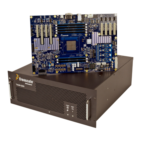
The QorIQ T4240 development system (T4240
QDS-16GPA) is a flexible system that supports the
24-virtual core T4240 processor. The T4240 QDS main
board is mounted in a 4U rack-mounted chassis and the main
PCB is a custom form factor.
An additional layer of flexibility for system clocking, power
distribution, and I/O multiplexing is built into the T4240
QDS. Eight expansion slots are provided for adding standard
PCIe cards or Freescale specialized SerDes riser cards (XFI
or XAUI networking). The T4240 QDS comes with a
Linux® board support package (BSP) that provides a
comprehensive starting point for Linux development efforts.
The T4240 QDS is available in two form factors:
•
T4240 QDS board installed in a chassis
•
T4240 QDS board as a stand-alone system
When you finish reading this document, you should be
familiar with:
•
T4240 QDS hardware kit contents
•
Board configuration settings
•
How to get started and boot the board
© 2013 Freescale Semiconductor, Inc. All rights reserved.
Document Number:T4240QDSQSG
Contents
1. Introduction . . . . . . . . . . . . . . . . . . . . . . . . . . . . . . . . . 2
2. Hardware Kit Contents . . . . . . . . . . . . . . . . . . . . . . . . 2
3. T4240 QDS Board Diagram . . . . . . . . . . . . . . . . . . . . 3
4. Connections and Switch Settings . . . . . . . . . . . . . . . . 4
5. Powering up and Booting System . . . . . . . . . . . . . . . 12
6. Pre-loaded RCW and Boot Flash Information . . . . . 33
7. Connecting a 750W Power Supply . . . . . . . . . . . . . . 34
8. Configuring T4240 QDS in Chassis . . . . . . . . . . . . . 38
Rev.0, 06/2013
Advertisement

Related Manuals for Freescale Semiconductor T4240


Summary of Contents for Freescale Semiconductor T4240
-
Page 1: Table Of Contents
24-virtual core T4240 processor. The T4240 QDS main 3. T4240 QDS Board Diagram ....3 board is mounted in a 4U rack-mounted chassis and the main 4. -
Page 2: Introduction
Serializer/Deserializer Reset Configuration Word Universal Serial Bus Physical Layer Interface Device Related Documentation The following table lists the documents that you can refer to for more information about T4240 QDS board operations. Table 1-2. Related Documentation Document Description CodeWarrior Kit Configuration Guide Explains how to setup hardware and software, and use each software component in the development kit. -
Page 3: T4240 Qds Board Diagram
600-75565: RS-232 Pro Series shielded serial cable, w/ DB-9 connectors • 600-75499: Ethernet Cable, straight through wiring, 6 ft. T4240 QDS Board Diagram Figure 1 Figure 2 shows the T4240 QDS board. Figure 1. T4240 QDS Board - Components T4240 QDS Quick Start Guide, Rev.0 Freescale Semiconductor... -
Page 4: Connections And Switch Settings
This section explains T4240 QDS connections and switch settings. Connection Settings In order to operate T4240 QDS and boot U-boat, you need to connect different cables to the board. Some of the cable connections are required, however, some of the connections are optional. - Page 5 DDR controllers, as shown in Figure 4. Otherwise, U-boat will not boot. Dims should be in the following slots: — J23 - D2_DIMM #1 — J22 - D1_DIMM #1 — J200 - D3_DIMM #1 T4240 QDS Quick Start Guide, Rev.0 Freescale Semiconductor...
- Page 6 Section 7, “Connecting a 750W Power Supply” for information about how to make connections. Figure 5. Power Supply – 6-pin to 8-pin12V supply power cable adapter, as shown in Figure T4240 QDS Quick Start Guide, Rev.0 Freescale Semiconductor...
- Page 7 The output cabling from the power supply consists of many cables, but only three of them are attached to the T4240 QDS board. Separate the three output power cables from the rest of the cabling bundle, as shown in Figure Figure 7.
- Page 8 T4240 QDS board. Be careful that connector latches align with the latching tab of the mating connector of the board. — Attach the 2x4 end of the 12V adapter cable to the EPS_12V header (J225) of the T4240 QDS board. Be careful that connector latch aligns with the latching tab of the mating connector of the board.
- Page 9 Figure 10 Figure 11 show these power connections before and after proper insertion in the board. Figure 10. Power Supply Connections (Before Insertion) Figure 11. Completed Power Supply Connections (After Insertion) T4240 QDS Quick Start Guide, Rev.0 Freescale Semiconductor...
- Page 10 7. PROMJET Adapter – Optional: A PROMJET (USB) adapter can also be attached at the PROMJET header (U112) for the purposes of downloading boot images. Note orientation of the PROMJET pod so that pin 1 is aligned properly as shown in Figure T4240 QDS Quick Start Guide, Rev.0 Freescale Semiconductor...
- Page 11 Ensure that the switch settings for SW1 through SW9 are configured as shown in Figure 15. For more details on decoding the switch settings, refer to the T4240 QDS Reference Manual. Figure 15. SW1-SW9 Switch Settings 4.2.1 Default Switch Settings...
-
Page 12: Powering Up And Booting System
SW1= 0x24 EEPROM. Note that for rev 1 T4240 devices, the RCW can not be sourced from NOR flash, so the I2C EEPROM is used as the default RCW location. As a backup, the RCW is also stored in the on-board eMMC device. - Page 13 3. After a few seconds, the board will power on with the LEDs illuminated as shown in the following figures, and the system will begin displaying the uboot output on the COM port screen. Figure 18. Power LEDs After Power-on: All ON Except POVDD T4240 QDS Quick Start Guide, Rev.0 Freescale Semiconductor...
- Page 14 Figure 19. PASS LED ON After Power-on: All Others are OFF Figure 20. M7 LED ON After Power-on: All Others are OFF 4. The following uboot text should be displayed on the COM port screen: U-Boot 2012.10 (Dec 08 2012 - 22:38:39) T4240 QDS Quick Start Guide, Rev.0 Freescale Semiconductor...
- Page 15 DDR: 6 GiB (DDR3, 64-bit, CL=11, ECC on) DDR Controller Interleaving Mode: 3-way 4KB Flash: 128 MiB 2048 KB enabled enable l2 for cluster 1 fec60000 enable l2 for cluster 2 feca0000 T4240 QDS Quick Start Guide, Rev.0 Freescale Semiconductor...
- Page 16 WARNING: adjusting available memory to 30000000 ## Booting kernel from Legacy Image at e8020000 ... Image Name: Linux-3.0.51-rt75 Image Type: PowerPC Linux Kernel Image (gzip compressed) Data Size: 4287063 Bytes = 4.1 MiB T4240 QDS Quick Start Guide, Rev.0 Freescale Semiconductor...
- Page 17 No /soc@ffe000000/qman@318000 property 'fsl,qman-fqd', using memblock_alloc(0000000000400000) No /soc@ffe000000/qman@318000 property 'fsl,qman-pfdr', using memblock_alloc(0000000001000000) Qman ver:0a01,03,00 No /soc@ffe000000/bman@31a000 property 'fsl,bman-fbpr', using memblock_alloc(0000000001000000) Bman ver:0a02,02,01 pme: No /soc@ffe000000/pme@316000 property 'fsl,pme-pdsr', using memblock_alloc(0x0000000001000000) pme: No /soc@ffe000000/pme@316000 property 'fsl,pme-sre', using memblock_alloc(0x0000000000a00000) T4240 QDS Quick Start Guide, Rev.0 Freescale Semiconductor...
- Page 18 MEM 0x0000000c40000000..0x0000000c5fffffff -> 0x00000000e0000000 IO 0x0000000ff8020000..0x0000000ff802ffff -> 0x0000000000000000 /pcie@ffe260000: PCICSRBAR @ 0xdf000000 /pcie@ffe260000: Setup 64-bit PCI DMA window /pcie@ffe260000: DMA window size is 0xdf000000 T4240 QDS board from Freescale Semiconductor Zone PFN ranges: 0x00000000 -> 0x00080000 Normal 0x00080000 -> 0x00180000...
- Page 19 IPIs... Brought up 24 CPUs devtmpfs: initialized xor: measuring software checksum speed 8regs 3382.000 MB/sec 8regs_prefetch: 2988.000 MB/sec 32regs 3274.000 MB/sec 32regs_prefetch: 3000.000 MB/sec xor: using function: 8regs (3382.000 MB/sec) T4240 QDS Quick Start Guide, Rev.0 Freescale Semiconductor...
- Page 20 1816 MB/s raid6: altivecx4 2823 MB/s raid6: altivecx8 3000 MB/s raid6: using algorithm altivecx8 (3000 MB/s) vgaarb: loaded SCSI subsystem initialized usbcore: registered new interface driver usbfs usbcore: registered new interface driver hub T4240 QDS Quick Start Guide, Rev.0 Freescale Semiconductor...
- Page 21 QMan: Allocated lookup table at 8000000000000000, entry count 65537 Qman portal initialised, cpu 0 Qman portal initialised, cpu 1 Qman portal initialised, cpu 2 Qman portal initialised, cpu 3 Qman portal initialised, cpu 4 T4240 QDS Quick Start Guide, Rev.0 Freescale Semiconductor...
- Page 22 Switched to NOHz mode on CPU #8 Switched to NOHz mode on CPU #19 Switched to NOHz mode on CPU #5 Switched to NOHz mode on CPU #15 Switched to NOHz mode on CPU #11 T4240 QDS Quick Start Guide, Rev.0 Freescale Semiconductor...
- Page 23 (no cpio magic); looks like an initrd Freeing initrd memory: 5848k freed fsl-ifc ffe124000.localbus: Freescale Integrated Flash Controller Freescale MEMAC MDIO Bus: probed mdio_bus mdio@ffe5fc000: /soc@ffe000000/fman@500000/mdio@fc000/mdio_onboard has invalid PHY address mdio_bus mdio@ffe5fc000: /soc@ffe000000/fman@500000/mdio@fc000/mdio-slot1 has invalid PHY address T4240 QDS Quick Start Guide, Rev.0 Freescale Semiconductor...
- Page 24 Freescale QDS Board MDIO Bus: probed mdio_bus xmdio-slot3@8: error probing PHY at address 2 Freescale QDS Board MDIO Bus: probed mdio_bus xmdio-slot4@8: error probing PHY at address 3 audit: initializing netlink socket (disabled) T4240 QDS Quick Start Guide, Rev.0 Freescale Semiconductor...
- Page 25 Sata FSL Platform/CSB Driver init scsi1 : sata_fsl ata2: SATA max UDMA/133 irq 69 fe8000000.nor: Found 1 x16 devices at 0x0 in 16-bit bank. Manufacturer ID 0x000001 Chip ID 0x002801 Amd/Fujitsu Extended Query Table at 0x0040 T4240 QDS Quick Start Guide, Rev.0 Freescale Semiconductor...
- Page 26 FMan MEMAC cpu3: fsl_mac: ffe5e6000.ethernet: FMan MAC address: 00:04:9f:02:7a:3a fsl_mac ffe5e8000.ethernet: FMan MEMAC cpu3: fsl_mac: ffe5e8000.ethernet: FMan MAC address: 00:04:9f:02:7a:3b fsl_mac ffe5ea000.ethernet: FMan MEMAC cpu3: fsl_mac: ffe5ea000.ethernet: FMan MAC address: 00:04:9f:02:7a:3c T4240 QDS Quick Start Guide, Rev.0 Freescale Semiconductor...
- Page 27 Using dynamic TX QM frame queues cpu3: fsl_dpa: ethernet.23: Using private BM buffer pools cpu3: Using dynamic RX QM frame queues cpu3: Using dynamic TX QM frame queues cpu3: fsl_oh: FSL FMan Offline Parsing port driver () T4240 QDS Quick Start Guide, Rev.0 Freescale Semiconductor...
- Page 28 USB Mass Storage support registered. i2c /dev entries driver mpc-i2c ffe118000.i2c: timeout 1000000 us rtc-ds3232 0-0068: rtc core: registered ds3232 as rtc0 mpc-i2c ffe118100.i2c: timeout 1000000 us mpc-i2c ffe119000.i2c: timeout 1000000 us T4240 QDS Quick Start Guide, Rev.0 Freescale Semiconductor...
- Page 29 USDPAA portal initialised, bman-uio-16 USDPAA portal initialised, bman-uio-15 USDPAA portal initialised, bman-uio-14 USDPAA portal initialised, bman-uio-13 USDPAA portal initialised, bman-uio-12 USDPAA portal initialised, bman-uio-11 USDPAA portal initialised, bman-uio-10 USDPAA portal initialised, bman-uio-f T4240 QDS Quick Start Guide, Rev.0 Freescale Semiconductor...
- Page 30 USDPAA portal initialised, qman-uio-d USDPAA portal initialised, qman-uio-c USDPAA portal initialised, qman-uio-b USDPAA portal initialised, qman-uio-a USDPAA portal initialised, qman-uio-9 USDPAA portal initialised, qman-uio-8 USDPAA portal initialised, qman-uio-7 USDPAA portal initialised, qman-uio-6 T4240 QDS Quick Start Guide, Rev.0 Freescale Semiconductor...
- Page 31 VFS: Mounted root (ext2 filesystem) on device 1:0. Freeing unused kernel memory: 324k freed INIT: version 2.88 booting Starting udev udev[1728]: renamed network interface eth3 to fm2-mac3 udev[1729]: renamed network interface eth4 to fm2-mac4 T4240 QDS Quick Start Guide, Rev.0 Freescale Semiconductor...
- Page 32 Public key portion is: ssh-rsa AAAAB3NzaC1yc2EAAAADAQABAAAAgwCmLyDCGacVAOKtPi0OVKOTB1qOUZNIyRZAvApOeP3gMeAeo6fQ9toYOCnQoCeAO BuRNMWTV6k+NGdkcx5sXWV7SWQwXNG8irP4s005x0JZFQRxlVZV6eBJjq+75lbykDuwPOWVpHGZOHxyKYICYF19ABi54h 6LD6jDmI4LkLofKGCv root@t4240qds Fingerprint: md5 5b:a4:c2:23:35:1f:5e:db:ea:6f:38:51:08:01:3d:4a dropbear. Starting system log daemon...0 Starting kernel log daemon...0 Stopping Bootlog daemon: bootlogd. Yocto (Built by Poky 7.0) 1.2 t4240qds ttyS0 T4240 QDS Quick Start Guide, Rev.0 Freescale Semiconductor...
-
Page 33: Pre-Loaded Rcw And Boot Flash Information
An alternate u-boot (golden) copy is located in Bank 4 with SW6[1:4]= 0100 The default FMan ucode location: 0xeff40000 On-board NOR flash loaded with these complete NOR flash image files: • rcw_1_28_6_12_1666MHz.bin • fsl_fman_ucode_B4860_106_3_4.bin • u-boot.bin • uImage T4240 QDS Quick Start Guide, Rev.0 Freescale Semiconductor... -
Page 34: Connecting A 750W Power Supply
AC plug. c) The output cabling from the power supply consists of many cables, but only three of them are attached to the T4240 QDS board. Separate the three output power cables from the rest of the cabling bundle, refer Figure T4240 QDS Quick Start Guide, Rev.0... - Page 35 Also ensure that the latching mechanism of the VGA1 connector aligns with the latching tab of the 6-pin adapter cable connector, as shown in Figure Figure 24. 12V Power Adapter Cable Attached to the 6-pin VGA1 Connector T4240 QDS Quick Start Guide, Rev.0 Freescale Semiconductor...
- Page 36 T4240 QDS board. Be careful that connector latch aligns with the latching tab of the mating connector of the board. – Attach the 2x4 end of the 12V adapter cable to the EPS_12V header (J225) of the T4240 QDS board. Be careful that connector latch aligns with the latching tab of the mating connector of the board.
- Page 37 Connecting a 750W Power Supply Figure 26. Power Supply Connections (Before Insertion) T4240 QDS Quick Start Guide, Rev.0 Freescale Semiconductor...
-
Page 38: Configuring T4240 Qds In Chassis
Configuring T4240 QDS in Chassis Figure 27. Completed Power Supply Connections (After Insertion) Configuring T4240 QDS in Chassis If the T4240 QDS comes in a chassis, it appears as shown in Figure T4240 QDS Quick Start Guide, Rev.0 Freescale Semiconductor... - Page 39 Configuring T4240 QDS in Chassis Figure 28. T4240 QDS in Chassis The differences between configuring the T4240 QDS standalone system and the T4240 QDS in chassis are: • In chassis, the main power supply is attached at right, inside the chassis. The main power switch is located at the back.
- Page 40 Freescale, the Freescale logo, CodeWarrior, and QorIQ are trademarks of Freescale Semiconductor, Inc., Reg. U.S. Pat. & Tm. Off. All other product or service names are the property of their respective owners. © 2013 Freescale Semiconductor, Inc. Document Number: T4240QDSQSG Rev.0...
Need help?
Do you have a question about the T4240 and is the answer not in the manual?
Questions and answers