
Subscribe to Our Youtube Channel
Related Manuals for Sega OutRun2SP


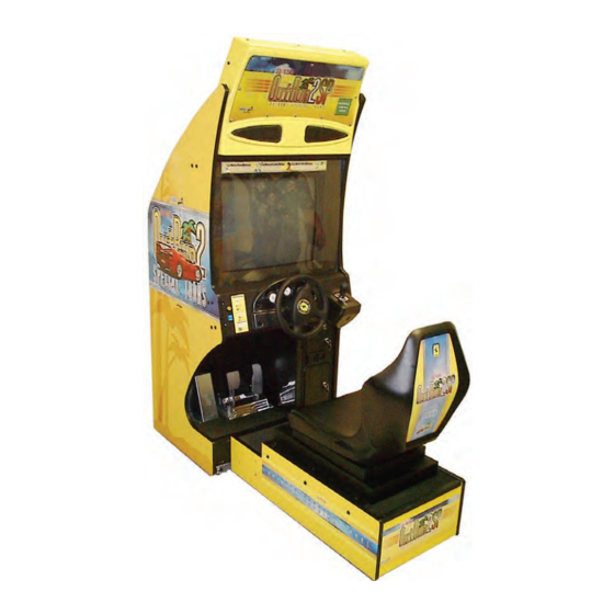
Summary of Contents for Sega OutRun2SP
- Page 1 1ST PRINTING MARCH ‘05 ® Standard Version Owner’s Manual SEGA AMUSEMENTS USA, INC. MANUAL NO. 999-2313 GAME CODE: ORP...
- Page 2 VISIT OUR WEBSITE! Now with a new look to make your experience that much easier.
- Page 3 BEFORE USING THE PRODUCT, BE SURE TO READ THE FOLLOWING: To maintain the safety: To ensure the safe usage of the product, be sure to read the following before using the product. The following instructions are intended for the users, operators and the personnel in charge of the operation of the product. After carefully reading and sufficiently understanding the warning displays and cautions, handle the product appropriately.
- Page 4 SEGA shall not be held responsible for any accidents, compensation for damage to a third party, resulting from the specifications not designated by SEGA.
-
Page 5: Table Of Contents
TABLE OF CONTENTS BEFORE USING THE PRODUCT, BE SURE TO READ THE FOLLOWING: TABLE OF CONTENTS INTRODUCTION OF THE OWNER’S MANUAL 1. HANDLING PRECAUTIONS ..................1 - 2 2. PRECAUTIONS CONCERNING INSTALLATION LOCATION ........3 - 4 3. OPERATION ........................5 - 8 4. -
Page 6: Introduction Of The Owners Manual
SEGA AMUSEMENTS USA, INC. / CUSTOMER SERVICE 45133 Industrial Drive, Fremont, California 94538, U.S.A. Phone : (415) 701-6580 Fax : (415) 701-6594 ◆ PRODUCTION DATE ◆ This SEGA product was produced in the year of: 2005 This signifies that this work was disclosed in 2005. - Page 7 DEFINITION OF LOCATION MAINTENANCE MAN AND SERVICEMAN Non-technical personnel who do not have technical knowledge and expertise should re- frain from performing such work that this manual requires the location's maintenance man or a serviceman to carry out, or work which is not explained in this manual. Failing to WARNING! comply with this instruction can cause a severe accident such as electric shock.
- Page 8 Notes:...
-
Page 9: Handling Precautions
• SEGA shall not be held responsible for damage, compensation for damage to a third party, caused by specification changes not designated by SEGA. - Page 10 ● Some parts are the ones designed and manufactured not specifically for this game machine. The manufacturers may discontinue, or change the specifications of, such general-purpose parts. If this is the case, Sega cannot repair or replace a failed game machine whether or not a warranty period has expired.
-
Page 11: Precautions Concerning Installation Location
2. PRECAUTIONS CONCERNING INSTALLATION LOCATION This product is an indoor game machine. Do not install it outside. Even indoors, avoid installing in places mentioned below so as not to cause a fire, electric shock, WARNING! injury and or malfunctioning. ● Places subject to rain or water leakage, or places subject to high humidity in the proximity of an indoor swimming pool and or shower, etc. - Page 12 To avoid machine malfunctioning and a fire, do not place any obstacles near the ventilation opening. ● SEGA shall not be held responsible for damage, compensation for damage to a third party, resulting from the failure to observe this instruction.
-
Page 13: Operation
3. OPERATION PRECAUTIONS TO BE HEEDED BEFORE STARTING THE OPERATION To avoid injury and trouble, be sure to constantly give careful attention to the behavior and man- ner of the visitors and players. In order to avoid accidents, check the following before starting the operation: ●... - Page 14 ● Do not put any heavy item on this product. Placing any heavy item on the product can cause a falling down accident or parts damage. WARNING! ● Do not climb on the product. Climbing on the product can cause falling down accidents.
- Page 15 ● To avoid electric shock and short circuit, do not allow the customers to unplug the power plug without a justifiable reason. WARNING! ● This product is intended for 1 Player only per seat. Playing the game by 2 or more Players riding on the seat together can cause falling down and collision accidents by striking head, hand, or elbow.
- Page 16 WARNING: HAZARD TO EPILEPTICS. ● A very small portion of the population has a condition which may cause them to experience epileptic seizures or have momentary loss of consciousness when WARNING! viewing certain kinds of flashing lights or patterns that are present in our daily environment.
-
Page 17: Name Of Parts
4. NAME OF PARTS Marquee 29” Monitor Steering Wheel Shift Lever Coin and Cashbox Door Seat Control Panel Accelerator & Brake Main Base TABLE 4 Dimensions and Weights Width x Length x Height Weight When assembled 30.5 in x 70 in 82 in ~680 LBS www.sauservice.com... -
Page 18: Accessories
5. ACCESSORIES When transporting the machine, make sure that the following parts are supplied. Magnetic cards for the recording of play results, and cleaning kits for cleaning the head of the card reader/writer are sold separately. Subsequent purchases of these items can be made by contacting the office listed on this Owner's Manual or the dealer from whom the product was originally pur- chased. - Page 19 The following Table 5b lists the parts that are separately marketed but are necessary when booting this product's software. When having unpacked the shipping crate, make sure that all the parts in this Table 5b are in the crate. If not so, contact where you have obtained the product. TABLE 5 b (610-0617-01A : GD-ROM DRIVE KIT) GD-ROM DRIVE GD-ROM DRIVE CARTON BOX...
- Page 20 HOW TO USE THE CARTON BOX (GD-ROM DRIVE) When you want to order for replacing or repairing service of the GD-ROM STOP drive that is used by the product, pack it in a carton box as instructed below, and then deliver the carton box to a service agent. If you do not observe the IMPORTANT! instruction, your order may not be accepted or may be charged additionally.
-
Page 21: Assembling And Installation
6. ASSEMBLING AND INSTALLATION Perform assembly work by following the procedure herein stated. Failing to comply with the ● instructions can cause electric shock hazard. WARNING! Perform assembling as per this manual. Since this is a complex machine, erroneous assembling can ●... - Page 22 SECURING IN PLACE (ADJUSTER ADJUSTMENT) Make sure that all of the adjusters are in contact with the floor. If they are not, the cabinet can move and cause an accident. WARNING! This product has 8 casters and 8 Adjusters. (FIG. 6. 2 a) When the installation position is determined, cause the adjusters to come into contact with the floor directly, make adjustments in a manner so that the casters will be raised approximately 5 mm from the floor and make sure that the machine position is level.
- Page 23 38.75 in. 4 in. 4 in. over FIG. 6. 2 e Provide ventilation space for the ventilation opening. Allow more than 28 in. of space for customer traffic. www.sauservice.com...
- Page 24 INSTALLING THE GD-ROM DRIVE (SETTING GD-ROM DISC) Carefully handle the GD-ROM drive so as not to contaminate the disc and the ● readout lens with stains and dust particles. Do not continue to use the scratched GD-ROM disc. The scratched GD-ROM ●...
- Page 25 ● Remove the 1 truss head screw that fixes the GD-ROM drive lid (DISC LID). And turn clockwise the lid to remove. TRUSS SCREW (1) M3×8 PHOTO 6. 3 b ● Set the GD-ROM disc onto the GD-ROM drive with its labeled side facing upward. ●...
- Page 26 ● Undo the lock on the side of the unit base and remove the Truss screws. ● Turn the knob to open the lock, and lower the seat towards the backrest. Slowly lower the backrest until it touches the floor to prevent damage to the seat components. Put a drop cloth on the floor to prevent damaging the surface of the seat components.
- Page 27 ● Connect the GD cable connector (for data communication) to the DIMM board. GD CABLE CONNECTOR PHOTO 6. 3 e ● Insert both the GD cable connector (for data communication) and the power cord connector into the GD-ROM drive. Be careful about an inserting direction in this instance. Make sure that the connectors are inserted firmly and completely.
- Page 28 Attach the accessory stickers to both the Game Board and the Media Board. KEY CHIP MEDI A BOARD PROJECTION FIG. 6. 5 c Return the ASSY MAIN BD (now installed with the GD-ROM drive) into the PTV cabinet. Fol- lowing the above-described actions in a reverse order, fix the base, connect the connectors, and clamp the wires/cables.
- Page 29 POWER SUPPLY, AND EARTH CONNECTION ● Be sure to independently use the power supply socket outlet equipped with an Earth Leakage Breaker. Using a power supply without an Earth Leakage WARNING! Breaker can cause a fire when electric leakage occurs. ●...
- Page 30 TURNING POWER ON Turn on the AC unit's main switch to supply power to the unit. Once power is turned on, the fluorescent lamp lights up. The Start System Screen displays after a lapse of several seconds. It is followed by the screen that indicates that the network is currently being checked if the communication mode has been set.
-
Page 31: Precautions When Moving The Machine
7. PRECAUTIONS WHEN MOVING THE MACHINE ● When moving the machine, be sure to unplug the power plug. Moving the machine with the plug as is inserted can damage the power cord and cause fire WARNING! and electric shock hazards. ●... - Page 32 ● When moving the unit short distances (ie. Room to Room) where the marquee will not clear doorways or other openings, the marquee can be folded back WARNING! on its hinge by removing the rear support brackets and the 3 indicated screws below.
-
Page 33: Game Description
8. Game Description The following explanations apply to the case the product is functioning satisfactorily. Should there be any moves different from the following contents, some sort of faults may have occurred. Immediately look into the cause of the fault and eliminate the cause thereof to ensure satisfactory operation. When the power is connected, the fluorescent lamp in the FL box is always on. - Page 34 8-1 BASIC CONTROLS FIG. 8. 1 Insert a coin and press the Start Button to begin a game. Choose your car, game mode, background music, and other options. View choices with the Steering Wheel, and enter your selection with the Gas pedal. During game play with the Steering Wheel, use the Gas pedal to accelerate your car, and the Brake pedal to stop.
- Page 35 A single course consists of 15 stages, with five separate goal areas. The game has two courses, the OutRun2SP course and the OutRun2 course (from the previous game). The three single player game modes are OutRun Mode, Heart Attack Mode, and Time Attack Mode.
- Page 36 8-3 SETUP SCREEN ORDER AND CONTENTS This section explains the available options and controls for the setup screens. 1. Versus Mode Entry If several machines are linked together, inserting a coin and pressing the Start Button on one machine will result in the message "Entry has been closed.
- Page 37 2. Single Player Setup (1) Player's Car Selection Controls: [Steering Wheel: View Choices], [Gas Pedal: Enter Selection], ["Brake Pedal" + "Shift": Color Change] The player can select one of the following 10 cars: ["F50", "Enzo Ferrari", "360 Spider" , "F40", "Testarossa", "288 GTO", "512 BB", "Dino 246 GTS", "365 GTS/4, Daytona", "250 GTO"] Changing the Car Color Pressing the Brake pedal displays the available colors for the player's car at the bottom-right of the...
- Page 38 (2) Transmission Selection Controls: [Steering Wheel: View Choices], [Gas Pedal: Enter Selection] After the player has selected a car, they can then choose the type of transmission. ●Automatic Transmission: Shifting up and down gears is performed automatically (the player does not use the Gear Shifter).
- Page 39 Note: See the section "8-4 Game Instructions" for further details of each mode. Pressing the View Change Button allows the player to select the course from the previous game, OutRun2. Pressing the View Change Button again allows the player to select the OutRun2SP course. www.sauservice.com...
- Page 40 (4) Game Mode Selection (15-Continuous Course Mode) When the 15-Continuous Course Mode is available, two icons for that mode are added to the game mode selection screen. Note: See the section "Test Mode" for information on how to setup 15-Continuous Course Mode. Points about the additional 15-Continuous Course Mode: ●...
- Page 41 Pressing the View Change Button enables the selection of courses from the previous game, OutRun2. It is possible to select a 15-Continuous Course from OutRun2. (5) Settings Selection (Time Attack Mode only) In Time Attack Mode, the player proceeds to the car settings screen after selecting the game mode. Controls: [Steering Wheel: View Choices], [Gas Pedal: Enter Selection] The following settings are available: ●...
- Page 42 (6) BGM Selection Controls: [Steering Wheel: View Choices], [View Change Button: Music Change], [Gas Pedal: Enter Selection], [Brake Pedal + Shift: Sound Balance Change] The in-game background music can be chosen from a total of 14 different tunes. By selecting the RANDOM icon on the far right, the music will be selected at random. The list of selectable music can be changed by pressing the View Change Button.
- Page 43 Controls: [Steering Wheel: View Choices], [Gas Pedal: Enter Selection] The player selects which stages the race will contain. ● Special: A course specially designed for versus races. This course combines stages from both OutRun2SP and OutRun2. ● OutRun2SP: The OutRun2SP course. ● OutRun2: The OutRun2 course.
- Page 44 Points about the additional 15-Continuous Course Mode: ● OutRun2SP 15-Continuous Course Mode: This allows the player to race 15 consecutive stages in OutRun2SP Mode. ● OutRun2 15-Continuous Course Mode: This allows the player to race 15 consecutive stages in OutRun2 Mode.
- Page 45 (3) Player's Car Selection Controls: [Steering Wheel: View Choices], [Gas Pedal: Enter Selection], [Brake pedal + Shift: Player Only Mode "PO" Entry], ([View Change + Shift: No Handicap "NH" Entry]) As with Single Player mode, there are 10 cars to choose from. In Versus Play mode, car colors are fixed - Player 1: Red, Player 2: Yellow, Player 3: White or Silver (depending on the car model), Player 4: Black.
- Page 46 (4) Transmission Selection This operation is carried out in the same way as described in the section "2. Single Player Setup". (5) BGM Selection This operation is carried out in the same way as described in the section "2. Single Player Setup". 4.
- Page 47 8-4 GAME INSTRUCTIONS 1. Common Features in All Modes Display Breakdown (All Modes) Time Counter Total Time Route Map Shift Up Indicator Tacho Meter Shift Indicator Speed Meter The time counter is displayed at the top-center of the screen. - If the time counter reaches zero, the game is over. - Extra time is added when a checkpoint is passed.
- Page 48 Game Controls (All Modes) How to Drift 1)After letting go of the Gas pedal, immediately press the Brake pedal. 2)Turn the Steering Wheel hard and fast in the direction of a corner and press the Gas pedal. When using Manual Transmission, drop down a gear just before a corner and turn the Steering Wheel hard in the direction of the corner.
- Page 49 2. Single Player: OutRun Mode Display Breakdown The score is displayed at the top-right of the screen, underneath this is an animated display of any points received for passing enemy cars. Game Instructions Put simply, this is a mode where you enjoy taking a drive with a girl. Choose either the left or right road when you come to a fork and aim to reach the finish line within the time limit.
- Page 50 3. Single Player: Heart Attack Mode Display Breakdown The number of hearts collected is displayed at the top-right of the screen. At the bottom-right of the screen, the total number of hearts collected and a girl's silhouette is displayed. As the total number of hearts collected increases, the girl's silhouette is filled out with color. Game Instructions In this mode, you impress a beautiful girl by doing everything she asks.
- Page 51 4. Single Player: Time Attack Mode Display Breakdown At the top-right of the screen, the lap time for each stage is displayed. (If the time is faster than the ghost car, it is displayed in green.) At the bottom-right of the screen, the time for each sector of the stage is displayed. When each sector is completed, ghost car information is displayed on the center left and right of the screen.
- Page 52 If you enter your name on the name entry screen you can also add that to the ghost car data. Even if you quit the game part way through, if you have recorded a faster time than the ghost car, you will have the opportunity to enter your name.
- Page 53 5. Versus Play Display Breakdown Opponent data is displayed at the top-right of the screen. Each player's information is indicated with a face icon, and their current status is shown by the expressions on the faces and with speech. The order of the faces changes to reflect the race order. Game Instructions The starting grid order is determined by the order of entry into the game.
- Page 54 - "OutRun 15-Continuous Course Mode" (Single Player) - "Time Attack 15-Continuous Course Mode" (Single Player) - "OutRun2SP 15-Continue Course Mode" (Versus Play) - "OutRun2 15-Continuous Course Mode" (Versus Play) The 15-Continuous Course Mode differs from the normal game in the following ways:...
- Page 55 7. Game Pause The game can be paused with the following combination of controls (in Single Player mode only): With the car stopped, press [Brake + View Change + Shift Up (Put the Gear Shifter in the down position while pressing the Brake Pedal and View Change Button down)] This combination of controls opens the pause window on the screen.
- Page 56 8-5 NAME ENTRY AND INTERNET RANKING 1. Name Entry Controls: [Steering Wheel: View Choices], [Gas Pedal: Enter Selection], [Brake Pedal: Delete], [Start Button: END] (Moving the Gear Shifter up and down selects letters.) This game has a function that can register all Single Player results with an Internet ranking system. After finishing a game in Single Player mode, the player enters their name for Internet ranking purposes, even if they have not achieved a rank on the actual machines they are playing on.
- Page 57 Pressing the View Change Button switches to the game's in-depth data display. Visit the following URL for Internet ranking registration and listings: http://outrun.jp/ The Internet ranking is calculated separately for the following game modes and courses: OutRun2SP Courses ● OutRun Mode: Each course (A - E) + the 15-Continuous Course ●...
- Page 58 8-6 CHARACTER INTRODUCTIONS Three major characters appear in the game. 1. Driver Name: Alberto Personal Info: Although easy-going on the outside, he's a real go-getter. He has a very distinguished driving sense. He's also quite rich. 2. OutRun Mode Lady Name: Jennifer Personal Info: She's a filthy rich 'princess', always selfishly seeking the next thrill.
-
Page 59: Explanation Of Test And Data Display
9. EXPLANATION OF TEST AND DATA DISPLAY By operating the switch unit, periodically perform the tests and data check. When installing the machine initially or collecting cash, or when the machine does not function correctly, perform checking in accordance with the explanations given in this section. The following shows tests and modes that should be utilized as applicable. - Page 60 9-1 SWITCH UNIT AND COIN METER Never touch places other than those specified. Touching places not specified can cause electric shock and short circuit accidents. CAUTION! STOP ● Adjust the sound to the optimum volume, taking into consideration the environmental requirements of the installation location. IMPORTANT! ●...
- Page 61 9-2 SYSTEM TEST MODE STOP ● Any settings that are changed by users during TEST MODE are saved upon exiting TEST MODE with the EXIT command in the SYSTEM MENU. If the unit is IMPORTANT! powered off prior to exiting, changes to settings will not take effect. ●...
- Page 62 B. MEDIA BOARD TEST STOP Powering off the system during the MEDIA BOARD TEST with a DIMM BOARD will erase the game program data. It may be necessary to reload the data. IMPORTANT! Always wait for the test to complete before attempting to exit. MEDIA BOARD TEST is used to check the memory and IC on the MEDIA BOARD connected to the Chihiro.
- Page 63 C. SYSTEM INFORMATION Use SYSTEM INFORMATION to check version and other information for system programs. Screens may differ depending on the type of MEDIA BOARD connected to the unit. SYSTEM INFORMATION MAIN BOARD REGION **** BOOT VERSION **** QC FIRM VERSION **** SC FIRM VERSION ****...
- Page 64 D. JVS TEST JVS TEST is used to verify the specs of the I/O BOARD connected to the Chihiro and to run input tests. I/O BOARD specs are displayed initially. Screens may differ depending on the type of I/O BOARD connected to the unit. JVS TEST INPUT TEST NEXT NODE...
- Page 65 INPUT TEST Screen JVS TEST INPUT TEST NODE SYSTEM PLAYER 1 0000 PLAYER 2 0000 COIN 1 0000 COIN 2 0000 ANALOG 1 0000 ANALOG 2 0000 ANALOG 3 0000 ANALOG 4 0000 ANALOG 5 0000 ANALOG 6 0000 ANALOG 7 0000 ANALOG 8 0000...
- Page 66 E. SOUND TEST Use SOUND TEST to test sound output and to select the stereo/mono/surround setting. SOUND TEST OUTPUT TYPE STEREO RIGHT SPEAKER LEFT SPEAKER →EXIT SELECT WITH SERVICE BUTTON AND PRESS TEST BUTTON ● Use the SERVICE Button to move the cursor to the desired test item. ●...
- Page 67 F. C.R.T. TEST Use the C.R.T. TEST to adjust monitor colours and verify screen size. COLOR CHECK Screen ● Monitor COLOR CHECK screen is displayed initially. Each of the colors (red, green and blue) is darkest at the far left and gets progressively lighter (32 steps) towards the right.
- Page 68 G. COIN ASSIGNMENTS Use COIN ASSIGNMENTS to set the credit rate for each coin inserted. ● Use the SERVICE Button to move the cursor to the desired test item. ● Press the TEST Button to change the setting or to open the detailed settings. ●...
- Page 69 COIN TO CREDIT RATE Set the CREDIT RATE for each coin inserted. The "x COIN(S) COUNT AS y CREDIT(S)" setting indicates that "Inserting x coins equals y credits". Set this to "FREE PLAY" to allow game play without credits. When (A) COIN CHUTE TYPE is set to "COMMON", COIN CHUTE #2 settings are restricted to some extent by the settings for COIN CHUTE #1.
- Page 70 GAME COST SETTING Use this mode to set the number of credits required to start a game. COIN ASSIGNMENTS GAME COST SETTING 1 Credit(s) to Start 1 Credit(s) to Select 15COURSE →EXIT SELECT WITH SERVICE BUTTON AND PRESS TEST BUTTON Set the number of credits required to start a game.
- Page 71 H. CLOCK SETTING Use CLOCK SETTING to set the Chihiro internal clock. CLOCK SETTING 20XX/XX/XX(XXX) XX:XX:XX YEAR MONTH HOUR MINUTE →EXIT SELECT WITH SERVICE BUTTON AND PRESS TEST BUTTON ● Use the SERVICE Button to move the cursor to the item to be set. ●...
- Page 72 I. NETWORK SETTING (CORE) Use the LAN PORT attached to the Main Board, and carry out the settings necessary for network communication. Note: This function is not available with this product. NETWORK SETTING (CORE) ->REMOTE(C) ENABLE IP ADDRESS(C) ---.---.---.--- SUBNET MASK(C) ---.---.---.--- GATE WAY(C) ---.---.---.---...
- Page 73 J. NETWORK SETTING (MEDIA) STOP This product should only be used with the factory settings indicated in this manual. Selecting certain options from the screens listed below may alter settings or bring up IMPORTANT! other screens. However, since these functions are not used by this machine, they are not described in this manual.
- Page 74 NETWORK TYPE Choose a type of the communication network. Set to ETHER in this game machine. NONE: Sets that the communication system does not perform. Sets to NONE when you don't set the network system. ETHER: Sets ETHER for the communication network. MOBILE: Sets a mobile communication terminal for the communication network.
- Page 75 9-3 GAME TEST MODE STOP When changing the game configuration, changes will not be enabled until the ENTER Game Test has been completed. Be sure to exit the Game Test Mode properly after IMPORTANT! configuration changes. Select ENTER GAME TEST from the System Menu screen to display the Game Test Menu screen as follows.
- Page 76 A. INPUT TEST Select INPUT TEST to display the following screen and check the status of input devices. This test should be used periodically to check that each input device is functioning correctly. INPUT TEST STEERING BRAKE GEAR POSITION START VIEW CHANGE SERVICE TEST...
- Page 77 B. OUTPUT TEST Select OUTPUT TEST to display the following screen and check the status of each lamp. This test should be used periodically to check that the lamps are functioning correctly. On this screen the cursor will switch automatically between items, lighting up the respective lamps. OUTPUT TEST START BUTTON -->...
- Page 78 C. DRIVE BOARD TEST Select DRIVE BOARD TEST to display DRIVE BOARD TEST the following screen. This performs an operation to initialize the Steering Wheel motor, so make sure that you do not touch the Steering Wheel. Once the initialization operation is Initializing the drive board complete, the following screen is displayed Please DO NOT touch the steering wheel.
- Page 79 D. GAME ASSIGNMENTS Select GAME ASSIGNMENTS to display the current game settings and make changes. Changes to settings are not enabled until Test Mode is exited. After changing settings, be sure to exit Test Mode. NOTE: When adjusting network play settings, DIFFICULTY, ADVERTISE SOUND, LANGUAGE, SPEEDOMETER, and QUICK START items will be decided by the cabinet with LINK_ID "1".
- Page 80 time for 1 play is longer than the normal game mode. (Default Setting: OFF) When this is set to OFF, players cannot play the 15 Continuous Course Modes. When this is set to ON CHARGE, players can play the 15 Continuous Course Modes.
- Page 81 <Network Versus Mode Cabinet Settings> Cases for four cabinets (A, B, C, and D) connected via network cable. 4-Cabinet Versus CABINET LINK_ID TOTAL MACHINE GROUP Status Four cabinets can compete. 3-Cabinet Versus CABINET LINK_ID TOTAL MACHINE GROUP Status Single play only. Three cabinets can compete.
- Page 82 E. BOOKKEEPING Select BOOKKEEPING to display the following three operating data screens. Press the TEST Button on the BOOKKEEPING 1/3 and BOOKKEEPING 2/3 screens to move to the second and third (BOOKKEEPING 3/3) screens. Press the TEST Button in the third screen to return to the Game Test Menu Screen.
- Page 83 BOOKKEEPING [GAME MODE INFO(1/2)] OUTRUN MODE OR2SP GOAL/PLAY: GOAL AVE TIME: 0'00"000 GOAL/PLAY: GOAL AVE TIME: 0'00"000 OR2SP-15 GOAL/PLAY: GOAL AVE TIME: 0'00"000 OR2-15 GOAL/PLAY: GOAL AVE TIME: 0'00"000 SELECT AVE TIME: 0'00"00 HEART ATTACK MODE OR2SP GOAL/PLAY: GOAL AVE TIME: 0'00"000 GOAL/PLAY: GOAL AVE TIME: 0'00"000 SELECT AVE TIME: 0'00"00...
- Page 84 F. BACKUP DATA CLEAR BACKUP DATA CLEAR Select BACKUP DATA CLEAR to display CLEAR ALL BACKUP DATA the following screen, and you can clear the CLEAR RANKING & GHOST CAR DATA ONLY BOOKKEEPING data, top score ranking CLEAR BOOKKEEP DATA ONLY data, or coin/credit related data.
-
Page 85: Handle Mechanism
10. HANDLE MECHANISM In order to prevent an electric shock and short circuit, be sure to turn power off before perform ● ing work by touching the interior parts of the product. WARNING! Be careful so as not to damage wirings. Damaged wiring can cause an electric shock or short ●... - Page 86 10 - 2 REPLACING AND ADJUSTING THE HANDLE’S VR Never touch places other than those specified. Touching places not specified can cause electric ● shock and/or short circuit. WARNING! After the replacement or adjustment of the VR, be sure to set the variable value of the VR in the ●...
- Page 87 10 - 3 GREASING Never touch places other than those specified. Touching places not specified can cause elec ● tric shock and/or short circuit. WARNING! After the replacement or adjustment of the VR, be sure to set the variable value of the VR in ●...
-
Page 88: Shift Lever
11. SHIFT LEVER In order to prevent electric shock and short circuit, be sure to turn off the ● power before performing work on the interior parts of the product. CAUTION! Be careful not to damage wiring. Damaged wiring can cause electric shock or short circuit. ●... - Page 89 11 - 2 SWITCH REPLACEMENT Each microswitch is secured with 2 screws. Remove the 2 screws and replace the Microswitch. After replacing the Switch, check to see if the switch is inputted as per Shift Lever operation in the Test Mode. www.sauservice.com...
-
Page 90: Accel & Brakes(S)
12. ACCEL & BRAKE(S) In order to prevent an electric shock and short circuit, be sure to turn power off before performing ● work by touching the interior parts of the product. Be careful so as not to damage wirings. Damaged wiring can cause an electric shock or short circuit ●... - Page 91 Check Volume values in the Test Mode. Since work is performed inside the energized cabinet, be very careful so as not to touch un- designated portions. Touching places not speci- fied can cause an electric shock or short circuit. Take out the 2 truss screws and remove the Front Cover from the Accel.
-
Page 92: Coin Selector
13. COIN SELECTOR HANDLING THE COIN JAM If the coin is not rejected when the REJECT button is pressed, open the coin chute door and open the selector gate. After removing the jammed coin, put a normal coin in and check to see that the selector correctly functions. - Page 93 COIN DOOR www.sauservice.com...
- Page 94 OPTIONAL DOLLAR BILL ACCEPTOR THE COIN DOOR ASSEMBLY USED ON OUTRUN 2 SPECIAL TOURS STANDARD COMES EQUIPPED TO ACCEPT A DOLLAR BILL ACCEPTOR. ALL NEEDED WIRING CONNECTIONS ARE CONVIENENTLY LOCATED INSIDE THE GAME FOR THIS APPLICATION. THE COIN DOOR CAN ACCCOMMODATE THE FOLLOWING VALIDA- TORS: HOLE POSITION#1 Mars 2000 series...
-
Page 95: Monitor
WARNING! ● Using the monitor by converting it without obtaining a prior permission is not allowed. SEGA shall not be liable for any malfunctioning and accident caused by said conversion. ● Primary side and Secondary side... - Page 96 For the purpose of static prevention, special coating is applied to the CRT face of this product. To protect the coating, pay attention to the following points. Damaging the coating film can cause electric shock to the customers. ● Do not apply or rub with a hard item (a rod with pointed edge, pen, etc.) to or on the CRT surfaces.
- Page 97 SANWA Monitor: 998-0162 (31K Mode) CONTRAST BRIGHT H SIZE H POSI V SIZE V POSI CONTRAST ....Adjust image contrast. BRIGHT ...... Controls screen brightness. H. SIZE ......Controls horizontal screen size. H. POSI ......Controls horizontal display position on screen. V. SIZE ......Controls vertical screen size.
-
Page 98: Periodic Inspection Table
15. PERIODIC INSPECTION TABLE The items listed below require periodic check and maintenance to retain the performance of this machine and to ensure safe business operation. When handling the controller, the player will be in direct contact with it . In order to always allow the player to enjoy the game, be sure to clean it regularly. - Page 99 CLEANING THE CABINET SURFACES When the cabinet surfaces are badly soiled, remove stains with a soft cloth dipped in water or diluted (with water) chemical detergent and squeezed dry. To avoid damaging surface finish, do not use such solvents as thinner, benzine, etc. other than ethyl alcohol, or abrasives, bleaching agent and chemical dustcloth.
-
Page 100: Game Board
16. GAME BOARD ● In order to prevent electric shock and short circuit hazards, be sure to turn power off before performing work. WARNING! ● Be careful not to damage the wires. Damaged wires may cause electric shock or short circuit or present a fire risk. - Page 101 16-1 REMOVING THE GD-ROM DRIVE ● Turn the power off. ● Open the game unit ● Remove the GD cable connector and the power cord connector from the GD-ROM drive. POWER CORD CONNECTOR GD CABLE CONNECTOR JST NH6P TRIFORCE Release the cables. PHOTO 19.
- Page 102 16-2 COMPOSITION OF THE GAME BOARD Once the Chihiro Board has the Key Chip inserted, it is this product's specialized Game Board. ASSY CASE BOX ORT FIG. 17. 2 a DIP SW SETTING Use this product with the DIP SW settings shown in the figure below. FIG.
- Page 103 16-3 REPLACING THE MAIN BOARD BATTERY ● To prevent overheating, explosion, or fire: • Do not recharge, disassemble, heat, incinerate, or short the battery. • Do not allow the battery to come into direct contact with metallic objects or other batteries. •...
- Page 104 16-4 REPLACING THE MEDIA BOARD BATTERY PACK Prohibitions and Cautions to Handle the Battery Pack Be careful when handling the battery pack. We bear no responsibility for problems caused by handling clearly contrary to the content of this manual. ● Do not disassemble the battery pack and the batteries. If you should fail to observe this instruction, the internal wires and/or protective devices may be damaged;...
- Page 105 ● Do not tightly seal the battery pack when installing it onto an external device. Flammable gas is generated from the battery when its safety mechanism has functioned. If you should fail to observe the above-described instruction, sparks from motors, switches, etc. may cause the gas to fire. Therefore, install the battery pack so that the gas can be quickly released from the external device.
- Page 106 If the GD-ROM read time becomes excessively long, it is likely that the Media Board battery pack life if running low. No battery pack charger is available. Follow the procedure to replace the battery pack. ● Remove 4 screws from the upper face of the board. ●...
-
Page 107: Network Play
17. NETWORK PLAY Up to 4 machines can be linked for network play. Properly connected network cables and correct network play settings are required for network play. 17-1 PRECAUTIONS REGARDING NETWORK PLAY SETUP ● Before starting to work, ensure that the Power SW is OFF. Failure to observe this can cause electric shock or short circuit. - Page 108 SPACING OF GAME MACHINES Be sure to secure space in excess of the described distance between machines. 700 mm 700 mm 700 mm 200 mm 200 mm 200 mm FIG. 18. 1 www.sauservice.com...
- Page 109 17-2 CONNECTING NETWORK CABLES To enable network play, the hubs inside each of the game machines involved must be connected with network (LAN) cables. Connect the hub inside one of the machines to the hubs in each of the other machines using LAN cables.
-
Page 110: Design Related Parts
18. DESIGN RELATED PARTS 999-2321 Marquee Artwork Underlay ORTS 999-1430 Label Epilepsy Warning ORTS 999-2319 FRI-2002 Decal Instruction ORTS Steering Emblem FRI 999-2316 Decal Monitor Side Right ORTS 999-2315 Decal Monitor Side Left ORTS 999-2317 999-2105 RPM Gauge Decal Seat Back ORTS 999-2115 Speed Gauge 999-2320... -
Page 111: Parts List
19. PARTS LIST 7 8 9 ITEM NO. PART NO. DESCRIPTION NOTE Local Purchase Fluorescent bulb 24” F20T12CW “Coolwhite” 999-0167 Leg Leveler 1/2-13 3” 999-0168 Caster 160-2 1/2 Swivel 999-2081 Seat Local Purchase Monitor Glass 3/16” x 28.875” x 22.688” 999-2110 Monitor Bezel 610-0408-91... - Page 112 Marquee ITEM NO. PART NO. DESCRIPTION NOTE 999-2324 OR2SPStd Marquee Bracket Right 999-2325 OR2SPStd Marquee Bracket Left 999-2326 OR2SPStd Marquee Piano Hinge 999-2010 Vent Air 4 Hole 999-2327 Marquee Bezel 999-2328 OR2SPStd Speaker Grill Marquee 999-2329 Marquee Plastic Clear Parts Not Indicated ITEM NO.
- Page 113 ASSY ACCEL&BRAKE (SPG-2200) www.sauservice.com...
- Page 114 ASSY ACCEL&BRAKE (SPG-2200) ITEM NO. PART NO. DESCRIPTION NOTE SPG-2201 BASE SPG-2202 ACCEL PEDAL SPG-2203 BRAKE PEDAL SPG-2204 ACCEL SPRING SPG-2205 BRAKE SPRING SPG-2206 SHAFT SPG-2207 ACCEL GEAR SPG-2208 BRAKE GEAR SPG-2209 NEUTRAL STOPPER SPG-2210 VR PLATE ACCEL SPG-2211 VR PLATE BRAKE SPG-2212 AMPL GEAR SPG-2213...
- Page 115 ASSY HANDLE MECHA (SPG-2500) D-1/2 www.sauservice.com...
- Page 116 ASSY HANDLE MECHA (SPG-2500) D-2/2 ITEM NO. PART NO. DESCRIPTION NOTE SPG-2501 HANDLE BASE SPG-2502 BASE LID SPG-2503 HANDLE SHAFT SPG-2504 PULLEY 20 S5M SPG-2505 PULLEY 60 S5M SPG-2506 MOTOR BRKT SPG-2507 VR BRKT SPG-2108 STOPPER BOLT SPG-2109 STOPPER RUBBER SPG-2453 KEY 4×4×40 ASK-3502...
- Page 117 ELECTRONICS LOWER ITEM NO. PART NO. DESCRIPTION NOTE 838-13578 Audio Power Amp 2ch. and Mixer Local Purchase 3A Slow Blow Fuse 998-0138 Isolation Transformer ER-503 998-0218 Line Filter Local Purchase 5A Slow Blow Fuse www.sauservice.com...
- Page 118 ELECTRONICS UPPER ITEM NO. PART NO. DESCRIPTION NOTE 843-0005D-01 Assy Case Box ORT USA 610-0617-01A Kit GD-Rom drive w/ Label 400-5443 Power Supply 838-14174 Servo Motor Drive BD. 610-0674 Power Protetor Unit for Chihiro 837-13551-92 I/O Control BD for JVS www.sauservice.com...
-
Page 119: Wire Color Code Table
20. WIRE COLOR CODE TABLE THE WIRE COLOR CODE is as follow: PINK SKY BLUE BROWN PURPLE LIGHT GREEN Wires other than those of any of the above 5 single colors will be displayed by 2 alphanumeric characters. BLUE YELLOW GREEN WHITE ORANGE... - Page 120 Notes: www.sauservice.com...
- Page 121 Warranty Your new Sega Product is covered for a period of 90 days from the date of shipment. This certifies that the Printed Circuit Boards, Power Supplies and Monitor are to be free of defects in workmanship or materials under normal operating conditions. This also certifies that all Interactive Control Assemblies are to be free from defects in workmanship and materials under normal operating conditions.
- Page 122 SEGA AMUSEMENTS USA, INC.
Need help?
Do you have a question about the OutRun2SP and is the answer not in the manual?
Questions and answers