Advertisement
Quick Links
QUICK START GUIDE FOR DEMONSTRATION CIRCUIT 1029
Multi Channel Power Supply Sequencer and Supervisor
DESCRIPTION
Demonstration circuit 1029 is for evaluating the per-
formance of the LTC2928 Multichannel Power Supply
Sequencer and Supervisor.
The LTC2928 sequences and monitors up to four
power channels in power up and power down, and it
monitors those channel outputs in the steady state,
when power goes to loads. Sequencing is accom-
plished by controlling the power supply enable inputs
or N-channel MOSFET gates with the LTC2928 control-
ling outputs. Supervisory functions include undervolt-
age and overvoltage monitoring, and capturing the
output state information in the event of a system fault.
Inherent fault detection circuitry can detect:
Stalled (during sequencing) supplies
I
Supplies with the output voltage not satisfying the
I
undervoltage or overvoltage conditions
System controller command errors
I
PERFORMANCE SUMMARY
Specifications are at T
= 25° C
A
SYMBOL
PARAMETER
V
V
Input Supply Range
CC
CC
V
HV
Input Supply Range
HVCC
CC
V
ON Threshold Voltage
ON
V
Voltage Monitor Reset Threshold Voltage VSEL=V
MON(TH)
V
Sequencing Thresholds
SEQ(TH)
0.67 V
MON(TH)
0.33 V
MON(TH)
0.1 V
MON(TH)
V
Enable Pin Voltage Output in ON State
EN
I
Enable Pin Pull-Up Current
EN(UP)
t
Sequence Timer Period, STMR
STMR
t
Power Good Timer Period
PTMR
t
Reset Timer
RTMR
V1
V1 Internal and External Input
V2
V2 Internal and External Input
V3
V3 Internal and External Input
V4
V4 Internal and External Input
TPV1
V1 Time Position
TPV2
V2 Time Position
TPV3
V3 Time Position
TPV4
V4 Time Position
Externally commanded faults
I
Sequencing faults.
I
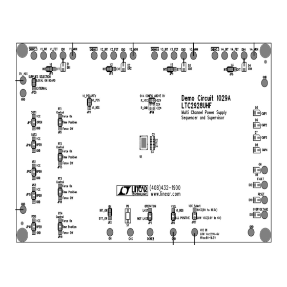
The board is populated with nineteen jumpers for se-
lection of the LTC2928 operation options and with
twelve LEDs for displaying:
The undervoltage status in the steady state CMP1
I
(D5)-CMP4 (D8)
The LTC2928 controlling outputs states EN1 (D1)-
I
EN4 (D4),
The state signals of the ON pin (#16), the RST# pin
I
(#21), the OV# pin (#20), and the FLT# pin (#19).
Design files for this circuit board are available. Call the
LTC factory.
, LTC and LT are registered trademarks of Linear
Technology Corporation. ThinSOT and PowerPath
are trademarks of Linear Technology Corporation.
CONDITIONS
V
Rising
•
ON
CC
Enable Pin ON, V
V
EN•( (
CC+4)
C
STMR=0.022UF
C
PTMR=2.2UF
C
RTMR=0.047UF
LTC2928
MIN
TYP
MAX
2.9
6.0
7.2
12.0
16.5
1.3
1.8
2.3
0.492
0.500
0.508
0.315
0.333
0.351
0.149
0.167
0.185
0.032
0.05
0.068
V
+4.5 V
+5.5
V
+6
CC
CC
CC
7.5
10
12.5
161
190
220
8.80
10.27
7.33
188.0
219.3
156.7
2.5
1.5
1.8
3.3
1
3
5
7
UNITS
V
V
V
V
V
V
V
uA
ms
s
ms
V
1
Advertisement

Related Manuals for Linear Technology 1029


Summary of Contents for Linear Technology 1029
- Page 1 QUICK START GUIDE FOR DEMONSTRATION CIRCUIT 1029 Multi Channel Power Supply Sequencer and Supervisor LTC2928 DESCRIPTION Demonstration circuit 1029 is for evaluating the per- Externally commanded faults formance of the LTC2928 Multichannel Power Supply Sequencing faults. Sequencer and Supervisor. The board is populated with nineteen jumpers for se-...
-
Page 2: Operating Principles
QUICK START GUIDE FOR DEMONSTRATION CIRCUIT 1029 Multi Channel Power Supply Sequencer and Supervisor OPERATING PRINCIPLES A single LTC2928 can control four positive supplies or The power good timer period defines the maximum three positive and one negative. time needed by any input supply to reach its undervolt-... -
Page 3: Quick Start Procedure
4. Press the button PB (S1) to change the ON signal from power supply. high to low and observe the output voltages. The Demonstration circuit 1029 is easy to set up to evaluate power-down output voltages should correlate with the the performance of the LTC2928 with the on-board sup- transient shown in Figure 2. - Page 4 QUICK START GUIDE FOR DEMONSTRATION CIRCUIT 1029 Multi Channel Power Supply Sequencer and Supervisor Figure 1. Demo Circuit 1029A Connections for Operation with Internal Supplies Figure 2. Power-Up and Power-Down Transients.
- Page 5 QUICK START GUIDE FOR DEMONSTRATION CIRCUIT 1029 Multi Channel Power Supply Sequencer and Supervisor Figure 3. Demo Circuit 1029A Connections for Operation with External Supplies...
- Page 6 QUICK START GUIDE FOR DEMONSTRATION CIRCUIT 1029 Multi Channel Power Supply Sequencer and Supervisor...
- Page 7 QUICK START GUIDE FOR DEMONSTRATION CIRCUIT 1029 Multi Channel Power Supply Sequencer and Supervisor...
- Page 8 QUICK START GUIDE FOR DEMONSTRATION CIRCUIT 1029 Multi Channel Power Supply Sequencer and Supervisor...
- Page 9 QUICK START GUIDE FOR DEMONSTRATION CIRCUIT 1029 Multi Channel Power Supply Sequencer and Supervisor...
- Page 10 QUICK START GUIDE FOR DEMONSTRATION CIRCUIT 1029 Multi Channel Power Supply Sequencer and Supervisor...
Need help?
Do you have a question about the 1029 and is the answer not in the manual?
Questions and answers