Advertisement
DESCRIPTION
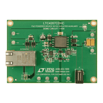
Demonstration circuit 1145B, featuring the LTC
provides a complete IEEE 802.3af Powered Device (PD)
interface and isolated 12V at 0.9A power supply solution
for use in Power over Ethernet (PoE) applications. An
optional connection is included for a 12V auxiliary supply
on the secondary side that disables PoE when present.
The LTC4267 integrates the 25k signature resistor, clas-
sification current source, thermal overload protection,
signature disable and power good signal along with an
undervoltage lockout optimized for use with the IEEE
required diode bridge. The precision dual level input cur-
PERFORMANCE SUMMARY
PARAMETER
Minimum Turn-on Voltage
Maximum Turn-off Voltage
Operating PoE Voltage
Maximum Input Current
Maximum Output Current
Output Voltage
PD Power Class
Auxiliary input voltage
Invalid Signature
Demonstration circuit 1145B interfaces with a customer's
PoE test setup per Figure 1. A PSE connects to DC1145B
through RJ45 connector J1. The front end of the demo
circuit includes the required Ethernet input interface
transformer and common mode termination integrated in
J1. The LTC4267 after J1 performs IEEE 802.3af interface
functions while data is passed to connector J3 to connect
to an optional PHY. The switching regulator function is
also carried out by the LTC4267 to output an isolated 12V.
Arrow.com.
Downloaded from
DEMO MANUAL DC1145B
Power over Ethernet Powered
Device With 12V Isolated Supply
®
4267,
rent limit allows the LTC4267 to charge load capacitors
and interface with legacy PoE systems.
The LTC4267 combines the above features with a current
mode switching controller designed for driving a 6V rated
N-channel MOSFET. It features programmable slope com-
pensation, soft-start, and constant frequency operation,
minimizing electrical noise even with light loads.
Design files for this circuit board are available at
http://www.linear.com/demo
L, LT, LTC, LTM, Linear Technology and the Linear logo are registered trademarks of Linear
Technology Corporation. All other trademarks are the property of their respective owners.
(T
= 25°C)
A
CONDITIONS
Input from PSE, I
=100mA
OUT
Input from PSE
Input from PSE, I
= 0 to Maximum Output Current
OUT
Input from PSE
Input from PSE, V
= 12V
OUT
Input from PSE, I
= 0 to Maximum Output Current
OUT
R
= R7 = 45.3 Ohm
CLASS
Input from auxiliary supply, dominant over PSE
PD input, auxiliary supply present
Diode bridges D2 and D6 provide the required auto-polarity
on the data pairs and spare pairs while C3 provides the
PD's 0.1μF capacitance during detection. This demo circuit
allows detection and power classification of the PD per the
IEEE 802.3af specification. During the detection process
of a PD, the LTC4267 displays the proper 25k signature
resistor. Classification is programmed by the selection
of a single external resistor R7 connected to the R
pin. DC1145B is set for Class 3, full power PD of 12.95W
at the input.
LTC4267
VALUE
39V
33V
37V to 57V
350mA
0.9A
12V ±2%
Class 3, 12.95W
10V to 16V
9kΩ
CLASS
dc1145bf
1
Advertisement
Table of Contents

Related Manuals for Linear Technology DC1145B


Summary of Contents for Linear Technology DC1145B
- Page 1 IEEE L, LT, LTC, LTM, Linear Technology and the Linear logo are registered trademarks of Linear required diode bridge. The precision dual level input cur- Technology Corporation. All other trademarks are the property of their respective owners.
- Page 2 DEMO MANUAL DC1145B OPERATING PRINCIPLES After detection and classification, the PD is powered up is achieved through transformer T1, capacitor C14 and when the input voltage exceeds the LTC4267 turn-on under- opto-isolators ISO1 and ISO2. voltage lock out (UVLO) through a dual-level current-limited The primary side power path is comprised of C1, L1, C9, power switch.
- Page 3 10. Remove the 12V auxiliary supply and verify the PSE through the PoE + and PoE – terminals. Only one set of power returns. – LOAD – – RJ45 RJ45 CAT5 CABLE Figure 1. DC1145B Test Setup dc1145bf Arrow.com. Arrow.com. Arrow.com. Downloaded from Downloaded from Downloaded from...
- Page 4 DEMO MANUAL DC1145B MEASURED DATA Figure 2 and 3 are measured data for a typical DC1145B. Vin=37V Vin=48V Vin=57V Output Current (A) Figure 2: Efficiency (Input Voltage (V ) is measured at RJ45 Jack) 12.05 12.04 12.03 12.02 12.01 Vin=37V 11.99...
- Page 5 DEMO MANUAL DC1145B PARTS LIST ITEM REFERENCE PART DESCRIPTION MANUFACTURER/PART NUMBER Required Circuit Components Cap., Elec. 4.7μF 63V 20% PANASONIC, EEEFK1J4R7R Cap., NPO 680pF 50V 10% 0805 AVX, 08055A681KAT2A Cap., X5R 0.1μF 100V 20% 1206 Taiyo Yuden, HMK316BJ104ML-T C4, C5 Cap., Tant.
- Page 6 DEMO MANUAL DC1145B PARTS LIST Res., Chip 100 0.1W 5% 0603 Vishay, CRCW0603100RJNEA Transformer, PoE Pulse, PA1138NL I.C., PoE Switching Reg. DFN(16)(DHC)5mm × 3mm Linear Tech.Corp.LTC4267CDHC#PBF I.C., Prog. Reference SO8NB Linear Tech. Corp., LT1431CS8#PBF Additional Demo Board Circuit Components C7, C12 (Opt) Cap., 0603...
- Page 7 Information furnished by Linear Technology Corporation is believed to be accurate and reliable. However, no responsibility is assumed for its use. Linear Technology Corporation makes no representa- tion that the interconnection of its circuits as described herein will not infringe on existing patent rights.
- Page 8 Linear Technology Corporation (LTC) provides the enclosed product(s) under the following AS IS conditions: This demonstration board (DEMO BOARD) kit being sold or provided by Linear Technology is intended for use for ENGINEERING DEVELOPMENT OR EVALUATION PURPOSES ONLY and is not provided by LTC for commercial use. As such, the DEMO BOARD herein may not be complete in terms of required design-, marketing-, and/or manufacturing-related protective considerations, including but not limited to product safety measures typically found in finished commercial goods.
Need help?
Do you have a question about the DC1145B and is the answer not in the manual?
Questions and answers