
Related Manuals for Clarke METALWORKER CDP10B


Summary of Contents for Clarke METALWORKER CDP10B
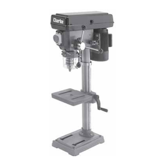
- Page 1 12 SPEED DRILL PRESS Model No’s: CDP10B & CDP15F OPERATING & MAINTENANCE INSTRUCTIONS SERIAL No....0905...
-
Page 2: Specifications
89/336/EEC Signed SPARE PARTS & SERVICING Please contact your nearest dealer, or CLARKE International, on one of the following numbers. PARTS - 020 8558 6696 : SERVICE - 020 8556 4443 PARTS & SERVICE FAX - 020 8558 3622 or E-MAIL PARTS - Parts@clarkeinternational.com... -
Page 3: Table Of Contents
INTRODUCTION Thank you for purchasing your CLARKE Drill Press. Before attempting to operate the machine, please read this instruction manual thoroughly, and follow all directions carefully. By doing so you will ensure the safety of both yourself and others around you, and at the same time, you should look forward to long and trouble free service from your Clarke Drill Press. -
Page 4: General Safety Precautions
GENERAL SAFETY RULES FOR OPERATING MACHINERY WARNING: As with all machinery, there are certain hazards involved with their operation and use. Exercising respect and caution will considerably lessen the risk of personal injury. However, if normal safety precautions are overlooked or ignored, personal injury to the operator or damage to property, may result. - Page 5 • • MAINTAIN MACHINE IN TOP ALWAYS ensure that ADEQUATE LIGHTING is CONDITION. available. A minimum intensity of 300 lux Keep tools sharp should be provided. Ensure that lighting is and clean for the placed so that you will not be working in your best and safest own shadow.
-
Page 6: Additional Safety Rules For Drill Presses
ADDITIONAL SAFETY RULES FOR DRILL PRESSES WARNING: THIS MACHINE MUST NOT BE MODIFIED, OR USED FOR ANY PURPOSE OTHER THAN THAT FOR WHICH IT IS DESIGNED. 1. IMPORTANT: You should not operate this machine unless you are thoroughly familiar with drilling machines and drilling techniques. -
Page 7: Electrical Connections And Wiring Diagram
ELECTRICAL CONNECTIONS Connect the mains lead to a standard, 230 Volt (50Hz) electrical supply through an approved 13 amp B3S 1363 plug, or a suitably fused isolator switch. WARNING! THIS APPLIANCE MUST BE EARTHED IMPORTANT: The wires in the mains lead are coloured in accordance with the following code: Green &... -
Page 8: Preparation For Use And Parts Identification
The following loose items are to be found in the packing case. Check the parts against the list below. Should there be any deficiencies or damage, you should contact your CLARKE dealer immediately . Head Assembly Chuck Guard... -
Page 9: Assembly
ASSEMBLY CAUTION! IT IS ADVISED THAT ASSISTANCE BE USED WHEN ASSEMBLING THIS MACHINE. NOTE: Ideally, the base should be firmly bolted to a workbench, or floor, prior to the assembly of other components. The mounting surface must flat, level, and capable of supporting the weight of the drill plus anticipated work. - Page 10 Head to Column. Fig. 4 NOTE: It may be necessary to unscrew the Head Lock Set Screws (A fig.4), to ensure they do not protrude internally, as this would prevent the head from sliding fully into position. 1. With assistance, raise the Head, and locate it on top of the Column, ensuring it slides home fully.
-
Page 11: Settings And Adjustments
SETTINGS and ADJUSTMENTS 1. Table. Fig.7 The table may be raised, lowered or swivelled about the column, by slackening off the table support locking handle, (Fig. 7), adjusting accordingly, and re-tightening the handle. It may also be tilted by loosening the screw, which secures the table to its’... -
Page 12: Drill Speed Table
3. Changing Drill (Spindle) Speed. Before changing the speeds, ensure the machine is switched OFF and disconnected from the mains supply. Fig. 11 1. Slacken off the Belt Tension Locking Screw (see fig.6), to relieve any tension on the drive belt. 2. -
Page 13: Operation
ON, it will not automatically start when the power is restored. b. A Micro switch is provided within the Pulley Cover, which prevents the machine from operating unless the Pulley Cover is firmly closed. Drill Press Vices, Cross Vices and Clamps, are available from your CLARKE dealer. -
Page 14: Maintenance
If the mains lead is worn or cut, or damaged in any way, it should be replaced immediately. Please refer to the trouble shooting chart on page 15 . If you are unable to rectify any faults, please contact your local dealer or Clarke International Service Division on 020 8988 7400 for assistance. Monthly (When in constant use) 1. -
Page 15: Trouble Shooting
F) Close pulley cover G) Micro Switch inoperative G) Check operation of micro switch, per instructions Page 10. If switch operates correctly but motor fails to start consult your Clarke dealer Drill binds A) Excessive feed pressure A) Apply less pressure in workpiece... -
Page 16: Parts Lists And Diagrams
PULLEY ASSEMBLY Item Description Part No Item Description Part No. Circlip QBCDP10BP13 1/19 Belt QBCDP10BP01 Bearing QBCDP10BP14 Bearing QBCDP10BP02 Spacer QBCDP10BP15 Idler Pulley QBCDP10BP03 Idler Shaft QBCDP10BP04 Shaft QBCDP10BP16 Motor Pulley QBCDP10BP05 Pulley QBCDP10BP17 Grub Screw QBCDP10BP06 Securing screw QBCDP10BP18 Cover Knob QBCDP10BP20 Cable Clamp... - Page 17 BASE ASSEMBLY Item Description Part No Item Description Part No Grubscrew QBCDP10BB01 Column (15F) QBCDP15FB10 Rack Collar QBCDP10BB02 10A Column (10B) QBCDP10BB10 not shown Bolt M8 (10B) QBCDP10BB11 Pinion QBCDP10BB03 11A Bolt M10 (15F) QBCDP15FB11 Handle Assy. QBCDP10BB04 not shown Round Table (15F) QBCDP15FB05 Table Tilt Bolt (10B)
- Page 18 HEAD ASSEMBLY Item Description Part No. tem Description Part No Spring Cover/Adjuster QBCDP10HB23 Locking Screw QBCDP10HB01 QBCDP10HB24 Grub Screw QBCDP10HB02 Head Assy QBCDP10HB25 Collar QBCDP10HB05 Allen Key QBCDP10HB27 Shaft QBCDP10HB07 Allen Key QBCDP10HB28 Screw QBCDP10HB08 Cable Assy QBCDP10HB30 Knob QBCDP10HB09 Adjuster Bar QBCDP10HB35 Handle...
- Page 19 QUILL ASSEMBLY Description Part No. No.Description Part No. Lock Nut QBCDP10QB01 Chuck Guard QBCDP10QB07 Flat Washer QBCDP10QB02 Bearing QBCDP10QB08 Bearing QBCDP10QB03 Spindle QBCDP10QB09 O-Ring QBCDP10QB04 10 Arbour QBCDP10QB10 Quill Shaft QBCDP10QB05 11 Chuck QBCDP10QB11 Wedge Drift QBCDP10QB06 12 Chuck Key QBCDP10QB12...
Need help?
Do you have a question about the METALWORKER CDP10B and is the answer not in the manual?
Questions and answers