
Subscribe to Our Youtube Channel
Related Manuals for APG True Echo GWR200


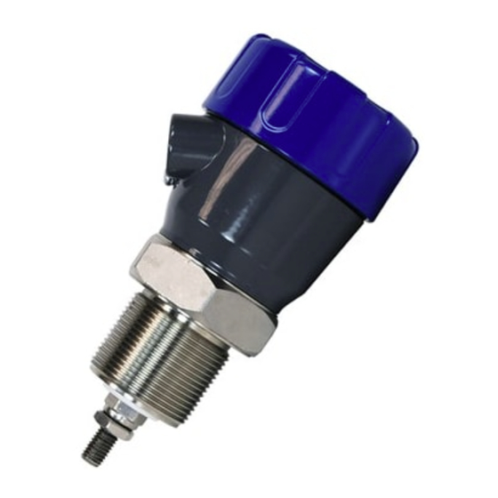
Summary of Contents for APG True Echo GWR200
- Page 1 True Echo ™ Guided Wave Radar Level Transmitter User Manual For the GWR200 Doc #9004784 Rev A, 05/2016...
-
Page 2: Table Of Contents
Table of Contents Introduction ........................ iii Warranty and Warranty Restrictions ..............iv Chapter 1: Specifications and Options ..............1 Dimensions ............................1 Specifications ........................... 2 Model Number Configurator ......................3 Wiring Diagram ..........................4 Chapter 2: Installation and Removal Procedure and Notes ........5 Tools Needed ............................ -
Page 3: Introduction
Reading your label Every APG sensor comes with a label that includes the instrument’s model number, part number, and serial number. Please ensure that the part number on your label matches your order. Tel: 1/888/525-7300 • Fax: 1/435/753-7490 • www.apgsensors.com • sales@apgsensors.com... -
Page 4: Warranty And Warranty Restrictions
Warranty and Warranty Restrictions This product is covered by APG’s waranty to be free from defects in material and workmanship under normal use and service of the product for 24 months. For a full explanation of our Warranty, please visit https://www.apgsensors.com/about-us/terms-conditions. -
Page 5: Chapter 1: Specifications And Options
Chapter 1: Specifications and Options • Dimensions NEMA 6 ENCLOSURE Standard Flange Option 4.3” (110mm) 4.3” (110mm) 6” (154mm) 2-9/16” (65mm) 7/8” (22mm) 2-7/8” (73mm) Tel: 1/888/525-7300 • Fax: 1/435/753-7490 • www.apgsensors.com • sales@apgsensors.com... -
Page 6: Specifications
• Specifications Performance Measurement Range 1.25’ to 80’ with minimum dielectric constant of 0.3 Communications Communications RS485 Modbus Response Time 100 samples/sec/updated <100 millisec. Electrical Output 4-20mA, Isolated 4-20 mA Loop Resistance 750 ohms (current loop 24VDC supply) 250 ohms (isolated 24 VDC supply) Operating Voltage 12-30 VDC Power Consumption... -
Page 7: Model Number Configurator
• Model Number Configurator Model Number: GWR200 - ____ - _____ - _____ - _____ - _____ - _____ - _____ E. Conduit Entries A. Wiring Option 1 ▲ □ Two 1/2” NPT □ 4-wire □ Two Cable Glands □ One 1/2”... -
Page 8: Wiring Diagram
• Wiring Diagram Isolated 4-20 mA Circuit True Echo Process Terminals Controller DC Gnd 4-20mA- 4-20mA+ Isolated 4-20mA Output 4-20 mA CURRENT LOOP TX A- Comm A TX B+ Comm B Supply Voltage DC In + DC In - DC Gnd Modbus Network Node TX A-... -
Page 9: Chapter 2: Installation And Removal Procedure And Notes
Chapter 2: Installation and Removal Procedures and Notes • Tools Needed • Appropriately sized wrenches for sensor installation and for probe connection • Flathead screwdriver for wire connections • Installation Notes The True Echo™ GWR200 should be installed in an area--indoors or outdoors--which meets the following conditions: •... -
Page 10: Mounting Instructions
• Choose “Install” from the options at the top of the zip file window. • The software will create True Echo.exe which will run from a folder in your Start Menu titled “APG”. Tel: 1/888/525-7300 • Fax: 1/435/753-7490 • www.apgsensors.com • sales@apgsensors.com... -
Page 11: Removal Instrustions
Chapter 3: Communications and Programming • True Echo™ Communication Tool The True Echo™ Communication Tool can be used in tandem with the APG True Echo™ Software to program and control your True Echo™ Level Transmitter. Through the True Echo™ Software, you can monitor the raw readings from the sensor, or configure multiple sensors. -
Page 12: Navigation Window Options
• Navigation Window Options MENU SELECTION DESCRIPTION OPTIONS File Load and save custom application settings Load / Save current setting Load Application setting View Adjust view settings, access options menu Toolbar Status Bar Options Help Access Help file & display True Echo version info Help ™... -
Page 13: True Echo™ Communication Software Overview
• True Echo™ Communication Software Overview The True Echo Software is included with the Communication Tool for easy setup and diagnostics of ™ the True Echo . This tool will allow the user interface into the programming, setup and diagnostics tools ™... - Page 14 Fig. 2) The Tank View Menu allows the user to view their application activity. The Quickset menu (fig 3) is found on the dropdown arrow of the Setup button. The Quickset menu contains the basic parameters required to get the unit up and running. It is one of the three main menu options in the internal software.
- Page 15 Empty Speed: Select the applications empty speed Damp Empty: Select the amount of dampening upon tank empty for stable reading DispMode: Select the default display mode in; Space, Material Level or % of Material Lock Code: Enter in a pass code number from 0 to 200 Fig.
- Page 16 Fig. 4) Factory Menu Tel: 1/888/525-7300 • Fax: 1/435/753-7490 • www.apgsensors.com • sales@apgsensors.com...
-
Page 17: Chapter 4: Maintenance
Chapter 4: Maintenance • General Care Your level sensor is very low maintenance and will need little care as long as it was installed correctly. However, in general, you should periodically inspect your True Echo™ GWR200 sensor to ensure the probe is free of any buildup that might impede the function of the sensor. - Page 18 Automation Products Group, Inc. Tel: 1/888/525-7300 • Fax: 1/435/753-7490 • www.apgsensors.com • sales@apgsensors.com...
Need help?
Do you have a question about the True Echo GWR200 and is the answer not in the manual?
Questions and answers