APG PT-500 Series Installation Manual
Pressure transmitters for analog output and modbus models
Hide thumbs
Also See for PT-500 Series:
- User manual (22 pages) ,
- Installation manual (2 pages) ,
- User manual (18 pages)
Table of Contents
Advertisement
Quick Links
Thank You
Thanks for purchasing a PT-500 series pressure transmitter from us! We appreciate your business
and your trust. Please take a moment to familiarize yourself with the product and this manual
before installation. If you have any questions, at any time, don't hesitate to call us at 888-525-7300.
NOTE: Scan the appropriate QR code to the below to see the full user manual on your
tablet or smartphone. Or visit www.apgsensors.com/support to find it on our website.
PT-500 Analog Output Manual
Table of Contents
1.Description
5. Dimensions
2. How To Read Your Label
3. Warranty
4. Mounting Instructions
Description
1
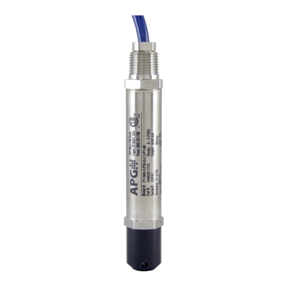
PT-500 submersible pressure transmitters offer reliability in harsh industrial conditions and
hazardous locations. The 4-20 mA version is certified intrinsically safe for hazardous areas in the
US and Canada by CSA for Class I, Division 2, Groups C and D, Class I, Zone 2, Group IIB, and Class
I, Division 1, Groups C and D, Class I, Zone 0, Group IIB environments. The small size, integrated
electronics, wide operating temperature range, and durability make the PT-500 the perfect
instrument for static and dynamic pressure measurement.
How To Read Your Label
2
Each label comes with a full model number, a part number, and a serial number. The model
number for the PT-500 will look something like this:
SAMPLE:
PT-500-400-FTH2O-G-L1-E0-P37-N0-500
The model number correlates with all the configurable options and tells you exactly what you have.
Compare the model number to the options on the datasheet to identify your exact configuration.
You can also call us with the model, part, or the serial number and we can help you.
The label also includes the pinout, as does this installation guide.
You'll also find all hazardous certification information on the label.
Warranty
3
This product is covered by APG's warranty to be free from defects in material and workmanship
under normal use and service of the product for 24 months. For a full explanation of our Warranty,
please visit https://www.apgsensors.com/about-us/terms-conditions. Contact Technical Support to
receive a Return Material Authorization before shipping your product back.
Scan the QR code below to read the full explanation of our Warranty on your tablet or smartphone.
Mounting Instructions
4
The PT-500 should be installed in an area--indoors or outdoors--which meets the following
conditions:
• Ambient temperature between -40°F and 185°F (-40°C to 85°C)
• Relative humidity up to 100%
• Altitude up to 2000 meters (6560 feet)
• IEC-664-1 Conductive Pollution Degree 1 or 2
• IEC 61010-1 Measurement Category II
• No chemical corrosive to stainless steel (such as NH
• Ample space for maintenance and inspection
• Class II power supply
Your PT-500 can be mounted in three ways: via NPT process connection, free-hanging suspension,
or conduit mounted. Mounting your pressure transducer is easy if you follow a few simple steps:
• Never over-tighten the sensor. This can compress the diaphragm, changing how it reacts to
pressure. In all cases, tighten the sensor as little as possible to create an adequate seal.
• Always use thread tape or sealant compound on tapered threads. Wrap thread tape in the
opposite direction of the threads so it does not unravel as you screw the sensor into place.
Unraveling can cause uneven distribution and seal failure.
• Always start screwing in your sensor by hand to avoid cross-threading. Thread failure can be a
problem if you damage threads by over-tightening them or by crossing threads.
• For suspension mounting the PT-500, drill a 3/16" hole into the 1/2" NPTF to 1/2" NPTF hex
coupler (P/N 511414) and secure it to the 1/2" NPTM coupler fitting of the PT-500. Attach a
.060" diameter 316L SS cable of desired length to the hex coupler and secure the steel cable
according to your application requirements.
PT-500 Modbus Manual
, SO
, Cl
, etc.)
3
2
2
Series PT-500 Pressure Transmitters
Installation Guide
For Analog Output and Modbus Models
APG
R
Automation Products Group, Inc.
1025 W 1700 N Logan, UT 84321
www.apgsensors.com | phone: 888-525-7300 | email: sales@apgsensors.com
Dimensions
5
0.99"
[25.1mm]
0.89"
[22.5mm]
1/2" NPTM
1.00"
[25.4mm]
4.93"
[125.2mm]
7.25"
[184.2mm]
1/2" NPTM
1.44"
Ø.188" THRU
[36.6mm]
PROTECTIVE
NOSE CONE
1.00"
[25.4mm]
PT-500...P1
0.95"
[24.1mm]
0.89"
[22.5mm]
1/2" NPTM
1.00"
[25.4mm]
7.19"
6.30"
[182.5mm]
[160.0mm]
NON-REMOVABLE
CAGE ASSEMBLY
1.65"
[41.9mm]
3.60"
[91.4mm]
PT-500...P37
IMPORTANT: Refer to section 12 for Hazardous Location Wiring.
Part # 122950-0004
Doc #9004122 Rev B
0.99"
[25.1mm]
0.89"
[22.5mm]
1/2" NPTM
1.00"
5.96"
[25.4mm]
[151.5mm]
5.08"
[129.0mm]
1.98"
0.31"
[50.3mm]
[8.0mm]
PT-500...P38
0.99"
[25.1mm]
0.89"
[22.5mm]
1/2" NPT
1.00"
[25.4mm]
7.36"
[186.9mm]
6.47"
REMOVABLE
[164.4mm]
SENSOR CAGE
ASSEMBLY
1.67"
[42.4mm]
3.60"
[91.4mm]
PT-500...P39
Advertisement
Table of Contents

Subscribe to Our Youtube Channel
Related Manuals for APG PT-500 Series


Summary of Contents for APG PT-500 Series
- Page 1 PT-500...P38 Warranty This product is covered by APG’s warranty to be free from defects in material and workmanship under normal use and service of the product for 24 months. For a full explanation of our Warranty, please visit https://www.apgsensors.com/about-us/terms-conditions. Contact Technical Support to receive a Return Material Authorization before shipping your product back.
- Page 2 Non-Incendive Wiring (4-20mA Output) Condensation in the vent tube can damage the electronics in your sensor, resulting in unreliable readings. APG offers two methods of preventing vent tube condensation: a venting cap and a desiccant drying cartridge. The venting cap is a PVC tube with a hydrophobic patch that allows moisture to pass out of the tube without allowing water in.
Need help?
Do you have a question about the PT-500 Series and is the answer not in the manual?
Questions and answers