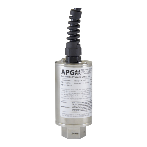
APG PT-400 Series User Manual
Hide thumbs
Also See for PT-400 Series:
- User manual (22 pages) ,
- Programming manual (20 pages) ,
- Installation manual (2 pages)
Subscribe to Our Youtube Channel
Summary of Contents for APG PT-400 Series
- Page 1 PT-400 User Manual Doc #9002825 Rev C4, 8/16 GlobalTestSupply www. .com Find Quality Products Online at: sales@GlobalTestSupply.com...
-
Page 2: Table Of Contents
Table of Contents Introduction ........................ iii Warranty Statement ....................iv Chapter 1: Specifications and Options..............1 Dimensions ............................1 Specifications ........................... 2 Model Number Configurator ......................3 Electrical Connectors and Pinout Table ..................4 Chapter 2: Installation and Removal Procedures and Notes ......5 Tools Needed ............................. -
Page 3: Introduction
Please take a few minutes to familiarize yourself with your PT-400 and this manual. The PT-400 series of pressure transmitters offers reliability over a wide range of pressures and in harsh industrial conditions and hazardous locations. It is certified intrinsically safe for hazardous areas in the US, Canada, Europe and internationally by CSA, ATEX, and IECEx for Class 1, Zone 0 environments. -
Page 4: Chapter 1: Specifications And Options
Chapter 1: Specifications and Options • Dimensions 5.80 147.32 1025 W 1700 N 1025 West 1700 N Logan, Utah USA Logan, Utah USA 888.525.7300 Automation Products Group, Inc. 888.525.7300 Automation Products Group, Inc. 4.45 Model #: Model #: Part #: Output: Part #: Output:... -
Page 5: Specifications
• Specifications Performance Pressure Ranges 0 to 10K PSIS (Per Part Number) Analog Output 4-20mA, 0-5VDC, 0-10VDC Over Pressure 2X Full Scale or limit of fitting, whichever is less Burst Pressure 3.0X Full Scale or limit of fitting, whichever is less Accuracy Linearity, Hystereses &... -
Page 6: Model Number Configurator
• Model Number Configurator Model Number: PT-400 - _____ - _____ - _____ - _____ - _____ - _____ - _____ - _____ - _____ - _____ A. Operation / Output F. Electrical Cable Length □ L1 ▲ 4 - 20 mA output □... -
Page 7: Electrical Connectors And Pinout Table
• Electrical Connectors, Pinout Table, and Supply Power Table PT-400 Series Pin Out Table 4-20 mA 0-5 VDC 0-10 VDC + Excitation + Excitation + Excitation - Excitation + Output + Output 6 Pin - Output - Output Bayonet - Excitation... -
Page 8: Chapter 2: Installation And Removal Procedures And Notes
Chapter 2: Installation and Removal Procedures and Notes • Tools Needed • Wrench sized appropriately for your PT-400’s process connection. • Thread tape or sealant compound for threaded connections. • Mounting Instructions Mounting your pressure transducer is easy if you follow a few simple steps: •... -
Page 9: Chapter 3: Maintenance
Chapter 3: Maintenance • General Care Your PT-400 series pressure transmitter is very low maintenance and will need little care as long as it is installed correctly. However, in general, you should: • Keep the transmitter and the area around it generally clean. -
Page 10: Re-Calibration
• Re-Calibration Ensure that the transducer is at 0 psig or 0 psia (vacuum if absolute), and adjust zero as per instruc- tions for zero trimming. • Apply full scale pressure to the pressure port and adjust the Span (“S”) pot (on the right of Figure 3.1) until the full scale signal is reached. -
Page 11: Chapter 4: Hazardous Location Installation And Certification
Chapter 4: Hazardous Location Installation and Certification • Intrinsically Safe Wiring Diagram (4-20mA Output) GlobalTestSupply www. .com Find Quality Products Online at: sales@GlobalTestSupply.com... -
Page 12: Non-Incendive Wiring Diagrams
• Non-Incendive Wiring Diagram (4-20mA Output) GlobalTestSupply www. .com Find Quality Products Online at: sales@GlobalTestSupply.com... - Page 13 • Non-Incendive Wiring Diagram (0-5VDC Output) GlobalTestSupply www. .com Find Quality Products Online at: sales@GlobalTestSupply.com...
- Page 14 • Non-Incendive Wiring Diagram (0-10VDC Output) GlobalTestSupply www. .com Find Quality Products Online at: sales@GlobalTestSupply.com...
-
Page 15: Csa Certificate Of Compliance
• CSA Certificate of Compliance Certificate of Compliance 1984045 237484 Certificate: Master Contract: 2587208 December 17, 2012 Project: Date Issued: Issued to: Automation Products Group Inc 1025 West 1700 North Logan, UT 84321 Attention: Karl Reid The products listed below are eligible to bear the CSA Mark shown with adjacent indicators 'C' and 'US' for Canada and US or with adjacent indicator 'US' for US only or without either indicator for Canada only. - Page 16 1984045 237484 Certificate: Master Contract: 2587208 December 17, 2012 Project: Date Issued: Ci = 0.055µF Li = 7.95µH • Model PT-400-L3/L10xxxx Pressure Transmitter. Rated 9-28VDC, 4-20mA or 0-5V, 20mA or 0-10V, 20mA; Maximum Ambient 85° C; Temperature Code T4; Maximum Working Pressure 10,000 PSI. Installed as per Drawing 9002794.
- Page 17 1984045 237484 Certificate: Master Contract: 2587208 December 17, 2012 Project: Date Issued: CLASS 2258 84 - Process Control Equipment - Intrinsically Safe, Entity - For Hazardous Locations - Certified to US Standards Class I, Div. 1, Groups C, D Class I, Zone 0, Group IIB Ex ia IIB T4;...
- Page 18 1984045 237484 Certificate: Master Contract: 2587208 December 17, 2012 Project: Date Issued: APPLICABLE REQUIREMENTS C22.2 No 0 - M1991 General Requirements - Canadian Electrical Code Part C22.2 No 0.4 - M2004 Bonding and Grounding of Electrical Equipment (Protective Grounding). C22.2 No 142 - M1987 Process Control Equipment.


Need help?
Do you have a question about the PT-400 Series and is the answer not in the manual?
Questions and answers