APG PT-400 Series Installation Manual
Pressure transmitters
Hide thumbs
Also See for PT-400 Series:
- User manual (22 pages) ,
- Programming manual (20 pages) ,
- User manual (22 pages)
Advertisement
Quick Links
Thank You
Thanks for purchasing a PT-400 series pressure transmitter from us! We appreciate your business
and your trust. Please take a moment to familiarize yourself with the product and this manual
before installation. If you have any questions, at any time, don't hesitate to call us at 888-525-7300.
NOTE: Scan the QR code to the right to see the full
user manual on your tablet or smartphone. Or visit
www.apgsensors.com/support to find it on our website.
Table of Contents
1.Description
5. Mounting Instructions
2. How To Read Your Label
6. Wiring Information
3. Warranty
7. Zero Trimming
4. Dimensions
8. Re-calibration
Description
1
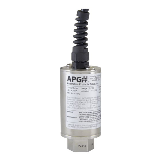
The PT-400 series pressure transmitter offers reliability over a wide range of pressures and in
harsh industrial conditions and hazardous locations. It is certified intrinsically safe for hazardous
areas in the US, Canada, Europe and internationally by CSA, ATEX, and IECEx for Class 1, Zone 0
environments.
How To Read Your Label
2
Each label comes with a full model number, a part number, and a serial number. The model
number for the PT-400 will look something like this:
SAMPLE:
PT-400-L1-100-PSI-G-E5-5-P5-N0-M1-S0
The model number correlates with all the configurable options and tells you exactly what you have.
Compare the model number to the options on the datasheet to identify your exact configuration.
You can also call us with the model, part, or the serial number and we can help you.
The label also includes the pinout, as does this installation guide.
You'll also find all hazardous certification information on the label.
Warranty
3
This product is covered by APG's waranty to be free from defects in material and workmanship
under normal use and service of the product for 24 months. For a full explanation of our Warranty,
please visit https://www.apgsensors.com/about-us/terms-conditions. Contact Technical Support to
recieve a Return Material Authorization before shipping your product back.
Scan the QR code below to read the full explanation of our Warranty on your tablet or smartphone.
Dimensions
4
Pigtail
5.80
147.32
1025 West 1700 N
Logan, Utah USA
888.525.7300
Automation Products Group, Inc.
Automation Products Group, Inc.
Model #:
Model #:
4.45
Part #:
Part #:
Output:
Range:
113.03
Wiring:
Serial #:
Serial #:
Pin A:
+ Exc
Date:
Pin B:
- Exc
Due:
Pin C:
N/C
Pin D:
N/C
Pin E:
N/C
Made in USA
Mfg:
Made in USA
Pin F:
N/C
1.50
38.10
9. General Care
10. Repair Information
11. Disassembly Instructions
12. Hazardous Location Wiring
DIN Connector
with L Bracket*
4 or 6 pin
Bayonet
Connector on
Extended Can
1025 W 1700 N
Logan, Utah USA
888.525.7300
Automation Products Group, Inc.
4.50
Model #:
Part #:
1025 W 1700 N
=
Output:
114.30
Logan, Utah USA
888.525.7300
Range:
=
Serial #:
Wiring
Pin A:
+Ex
Date:
Pin B:
-Ex
3.50
Due:
Pin C:
N/C
Pin D:
N/C
Output:
Pin E:
N/C
88.90
Range:
Made in USA
Pin F:
N/C
Mfg:
Wiring
Pin A:
+Ex
Date:
Pin B:
-Ex
Due:
Pin C:
N/C
Pin D:
N/C
Pin E:
N/C
Pin F:
N/C
Mfg:
1.50
38.10
1.50
38.10
* Total length of PT-400 with DIN Connector and L Bracket
is equal to total length of PT-400 with Pigtail.
PT-400 Series Pressure Transmitters
Installation Guide
For The PT-400
APG
Automation Products Group, Inc.
1025 W 1700 N Logan, UT 84321
www.apgsensors.com | phone: 888-525-7300 | email: sales@apgsensors.com
Mounting Instructions
5
The PT-400 should be installed in an area--indoors or outdoors--which meets the following
conditions:
• Ambient temperature between -40°F and 185°F (-40°C to 85°C)
• Relative humidity up to 100%
• Altitude up to 2000 meters (6560 feet)
• IEC-664-1 Conductive Pollution Degree 1 or 2
• IEC 61010-1 Measurement Category II
• No chemical corrosive to stainless steel (such as NH
• Ample space for maintenance and inspection
• Class II power supply
Mounting your pressure transducer is easy if you follow a few simple steps:
• Never over-tighten the sensor. This can compress the diaphragm, changing how it reacts
to pressure. In all cases, tighten the sensor as little as possible to create an adequate seal.
On straight threads, tighten only until you feel the o-ring compress - making sure you don't
damage or extrude the o-ring.
• Always use thread tape or sealant compound on tapered threads. Straight threads use an
o-ring. If using thread tape, wrap the tape in the opposite direction of the threads so it does
not unravel as you screw it into place. Unraveling can cause uneven distribution and seal
failure.
• Always start screwing in your sensor by hand to avoid cross-threading. Thread failure can be a
problem if you damage threads by over-tightening them or by crossing threads.
Wiring Information
6
PT-400
A
F
B
E
C
D
A
D
B
C
4
1
2
3
4
3
1
2
4 or 6 pin
Bayonet
Connector
N/C indicates no connection
For alternate pinouts, please consult factory
PT-400 Series Supply Power Table
1025 W 1700 N
Logan, Utah USA
888.525.7300
Automation Products Group, Inc.
Model #:
Part #:
Power Supply
Output:
Range:
Wiring
Serial #:
Pin A:
+Ex
Date:
Pin B:
-Ex
Due:
Pin C:
N/C
Pin D:
N/C
Pin E:
N/C
Made in USA
Pin F:
N/C
Mfg:
IMPORTANT: Refer to section 12 for Hazardous Location Wiring.
1.50
38.10
IMPORTANT: PT-400 Modbus sensors use reversed Tx+/Tx- pins. When connecting to your
system, ensure continuity of Tx- to Tx- and Tx+ to Tx+, rather than A to A and B to B.
R
, SO
3
Series
Pin Out Table
4-20 mA
0-5 / 0.5-4.5 / 1-5 VDC
A
+ Excitation
+ Excitation
B
- Excitation
+ Output
C
N/C
- Output
D
N/C
- Excitation
E
N/C
N/C
F
N/C
N/C
A
+ Excitation
+ Excitation
B
- Excitation
+ Output
C
N/C
- Output
D
N/C
- Excitation
1
+ Excitation
+ Excitation
2
- Excitation
+ Output
3
N/C
- Output
4
Case GND
- Excitation
1
+ Excitation
+ Excitation
2
- Excitation
+ Output
3
N/C
- Output
4
N/C
- Excitation
Red
+ Excitation
+ Excitation
Grn
N/C
+ Output
Wht
N/C
- Output
Blk
- Excitation
- Excitation
Shld
Gnd
Gnd
4-20 mA
0-5 / 0.5-4.5 / 1-5 VDC
9-28 VDC
9-28 VDC
Part # 122950-0001
Doc #9004026 Rev C
, Cl
, etc.)
2
2
0-10 VDC
RS-485
+ Excitation
+ Excitation
+ Output
- Excitation
- Output
N/C
- Excitation
B (Tx-)
N/C
A (Tx+)
N/C
Case GND
+ Excitation
N/A
+ Output
N/A
- Output
N/A
- Excitation
N/A
+ Excitation
+ Excitation
+ Output
A (Tx+)
- Output
B (Tx-)
- Excitation
- Excitation
+ Excitation
+ Excitation
+ Output
A (Tx+)
- Output
- Excitation
- Excitation
B (Tx-)
+ Excitation
+ Excitation
+ Output
B (Tx-)
- Output
A (Tx+)
- Excitation
- Excitation
Gnd
0-10 VDC
RS-485
12.5-28 VDC
9-28 VDC
Advertisement

Subscribe to Our Youtube Channel
Related Manuals for APG PT-400 Series


Summary of Contents for APG PT-400 Series
- Page 1 Mounting Instructions Description The PT-400 series pressure transmitter offers reliability over a wide range of pressures and in The PT-400 should be installed in an area--indoors or outdoors--which meets the following harsh industrial conditions and hazardous locations. It is certified intrinsically safe for hazardous...
- Page 2 Zero Trimming General Care • Remove the protective screw. Your pressure transmitter is very low maintenance and will need little care. As long as it was • Ensure that the transducer is at 0 psig or 0 psia (vacuum if absolute). For compound ranges, installed correctly, it will need very little care and maintenance.
Need help?
Do you have a question about the PT-400 Series and is the answer not in the manual?
Questions and answers