Advertisement
Quick Links
Thank You
Thanks for purchasing an RPM resistive continuous float level transmitter from us! We appreciate
your business and your trust. Please take a moment to familiarize yourself with the product and this
manual before installation. If you have any questions, at any time, don't hesitate to call us at 888-
525-7300.
You can also find a full list of our product manuals at:
www.apgsensors.com/resources/product-resources/user-manuals
Table of Contents
1. Description
5. Mounting and Installation
Instructions
2. How To Read Your Label
6.Wiring Terminals for Voltage
3. Warranty
Output
4. Dimensions
7. Removal Instructions
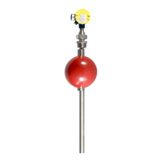
Description
1
The RPM utilizes reed switches in the instrument's stem and a permanent magnet in the float.
As the float rises or falls with the level of the liquid, the magnet inside the float acts on the reed
switches inside the stem and provides a resistive-chain output. The RPM is also available with
optional electronics that convert the resistance output into a 4-20mA signal.
How To Read Your Label
2
Each label comes with a full model number, a part number, and a serial number. The model
number for the RPM will look something like this:
RPM-96-A-F-AIS-011-0-2-00
SAMPLE:
The model number correlates with all the configurable options and tells you exactly what you have.
Compare the model number to the options on the datasheet to identify your exact configuration.
You can also call us with the model, part, or the serial number, and we can help you.
You'll also find all hazardous certification information on the label.
Warranty
3
This product is covered by APG's warranty to be free from defects in material and workmanship
under normal use and service of the product for 24 months. For a full explanation of our Warranty,
please visit www.apgsensors.com/resources/warranty-certifications/warranty-returns/. Contact
Technical Support to receive a Return Material Authorization before shipping your product back.
Dimensions
4
1.25"
31.8 mm
8. Offset and Span Calibration
9. General Care
10. Repair Information
11. Hazardous Location Wiring
RPM Dimensions
4.5"
114 mm
4.43"
113 mm
S1
L
M
S2
RPM Resistive Level Transmitter
Installation Guide
For RPM Series
APG
R
Automation Products Group, Inc.
1025 W 1700 N Logan, UT 84321
www.apgsensors.com | phone: 888-525-7300 | email: sales@apgsensors.com
Mounting and Installation Instructions
5
The RPM should be installed in an area--indoors or outdoors--which meets the following
conditions:
• Ambient temperature between -40°F and 185°F (-40°C to 85°C)
• Relative humidity up to 100%
• Altitude up to 2000 meters (6560 feet)
• IEC-664-1 Conductive Pollution Degree 1 or 2
• IEC 61010-1 Measurement Category II
• No chemical corrosive to stainless steel (such as NH
• Ample space for maintenance and inspection
Additional care must be taken to ensure:
• The sensor is located away from strong magnetic fields, such as those produced by motors,
transformers, solenoid valves, etc.
• The medium is free from metallic substances and other foreign matter.
• The sensor is not exposed to excessive vibration.
• Do not locate your RPM sensor near inlets/outlets.
Mounting Instructions:
• Clamp Mounting: Tighten a U-bolt stainless steel mounting bracket around the RPM's stem,
just below the union.
• Flange Mounting: Provide the compatible mating flange on the tank and install using a
suitable gasket.
• Plug Mounting: Provide the compatible female boss on the tank and install the probe with
thread tape.
Installation Notes:
• If there is surface wave action, then use a time-delay relay or stilling tube. If a stilling tube is
used, drill vent holes in the tube and use a spacer to assure the float has free travel inside the
tube (See Figure 5.1).
Mounting Bracket
Bottom Mounting Bracket
DANGER: Do not remove the housing cover until the atmosphere is
determined safe, and the power supply is turned off.
Wiring Terminals for Voltage Operation
6
The wiring of your RPM is as follows:
• Red and black wires connect to each end of a resistive chain.
• The white wire is the voltage output that is connected to different points on the resistive
chain by reed switches.
• Red Wire: +5 to +24 VDC
• Black Wire: Ground
• White Wire: Voltage Out
IMPORTANT: Your RPM MUST be installed according to drawing
9001415 (Explosion Proof Wiring Drawing) or 9001414 (Intrinsically
Safe Wiring Drawing) to meet listed approvals. Faulty installation will
invalidate all safety approvals and ratings.
, SO
, Cl
, etc.)
3
2
2
Top of Tank
Mounting Bracket
Stilling Tube
Inflow
Bottom Mounting Bracket
Figure 5.1
Part # 200854
Doc # 9006508 Rev B
Top of Tank
Inflow
Advertisement

Related Manuals for APG RPM Series


Summary of Contents for APG RPM Series
- Page 1 • Flange Mounting: Provide the compatible mating flange on the tank and install using a This product is covered by APG’s warranty to be free from defects in material and workmanship suitable gasket. under normal use and service of the product for 24 months. For a full explanation of our Warranty, please visit www.apgsensors.com/resources/warranty-certifications/warranty-returns/.
- Page 2 General Care Removal Instructions RPM resistive continuous float level transmitter Your is very low maintenance and will need little Removing your RPM from service must be done with care. It’s easy to create an unsafe situation, care as long as it is installed correctly. However, in general, you should: or damage your sensor, if you are not careful to follow these guidelines: •...
- Page 3 Hazardous Location Wiring Explosion Proof Wiring Drawing Intrinsically Safe Wiring Drawing...
Need help?
Do you have a question about the RPM Series and is the answer not in the manual?
Questions and answers